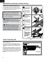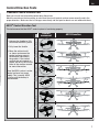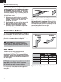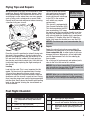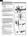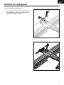
1
™ UMX PT-17 Instruction Manual Bedienungsanleitung Manuel d’utilisation Manuale di Istruzioni EN NOTICE All instructions, warranties and other collateral documents are subject to change at the sole discretion of Horizon Hobby, LLC. For up-to-date product literature, visit www.horizonhobby.com and click on the support tab for this product. Meaning of Special Language: The following terms are used throughout the product literature to indicate various levels of potential harm when operating this product: NOTICE: Procedures, which if not properly followed, create a possibility of physical property damage AND little or no possibility of injury. CAUTION: Procedures, which if not properly followed, create the probability of physical property damage AND a possibility of serious injury. WARNING: Procedures, which if not properly followed, create the probability of property damage, collateral damage, and serious injury OR create a high probability of superficial injury. WARNING: Read the ENTIRE instruction manual to become familiar with the features of the product before operating. Failure to operate the product correctly can result in damage to the product, personal property and cause serious injury. This is a sophisticated hobby product. It must be operated with caution and common sense and requires some basic mechanical ability. Failure to operate this product in a safe and responsible manner could result in injury or damage to the product or other property. This product is not intended for use by children without direct adult supervision. Do not use with incompatible components or alter this product in any way outside of the instructions provided by Horizon Hobby, LLC. This manual contains instructions for safety, operation and maintenance. It is essential to read and follow all the instructions and warnings in the manual, prior to assembly, setup or use, in order to operate correctly and avoid damage or serious injury. Age Recommendation: Not for children under 14 years. This is not a toy. Safety Precautions and Warnings • Always keep a safe distance in all directions around your model to avoid collisions or injury. This model is controlled by a radio signal subject to interference from many sources outside your control. Interference can cause momentary loss of control. • Always operate your model in open spaces away from full-size vehicles, traffic and people. • Always carefully follow the directions and warnings for this and any optional support equipment (chargers, rechargeable battery packs, etc.). • Always keep all chemicals, small parts and anything electrical out of the reach of children. • Always avoid water exposure to all equipment not specifically designed and protected for this purpose. Moisture causes damage to electronics. • Never place any portion of the model in your mouth as it could cause serious injury or even death. 2 • Never operate your model with low transmitter batteries. • Always keep aircraft in sight and under control. • Always use fully charged batteries. • Always keep the transmitter powered on while aircraft is powered. • Always remove batteries before disassembly. • Always keep moving parts clean. • Always keep parts dry. • Always let parts cool after use before touching. • Always remove batteries after use. • Always ensure failsafe is properly set before flying. • Never operate aircraft with damaged wiring. • Never touch moving parts. EN Table of Contents Charger Warnings ..................................................4 Battery Charging....................................................4 Transmitter and Receiver Binding...........................5 Low Voltage Cutoff (LVC) ........................................5 Flight Battery Installation and ESC Arming..............6 Center of Gravity (CG) ............................................6 Control Direction Tests ...........................................7 Control Centering ..................................................8 Control Horn Settings .............................................8 Dual Rates .............................................................8 Flying Tips and Repairs ..........................................9 Post Flight Checklist ..............................................9 Power Components Service .................................10 Installing the Landing Gear ..................................11 Troubleshooting Guide .........................................12 Limited Warranty .................................................13 Warranty and Service Information ........................15 Compliance Information for the European Union ...15 Replacement Parts...............................................58 Optional Parts and Accessories ............................59 Specifications 15.3 in (388mm) Installed 12.2 in (310mm) Motor: 8.5mm Brushed Motor Receiver: Spektrum™ AS6410 DSMX® 6Ch UM AS3X® Receiver ESC (SPMAR6410L) Servo: (2) 2.3-Gram Performance Linear Long Throw Servo (SPMSA2030L) (1) 1.8-Gram Linear Servo (SPMSA2005) Included Battery: 150mAh 1S 3.7V 25C Li-Po (EFLB1501S25) Battery Charger: E-flite® 1S USB Li-Po Charger, 300mA (EFLC1008) 1.7oz (48 g) Wing Area: 67.5 sq in (435 sq cm) Needed to Complete Recommended Transmitter: Spektrum™ DSM2®/DSMX® full range with dual-rates (DX4e and up) Preflight Checklist 1. Charge flight battery. 7. Set dual rates. 2. Install flight battery in aircraft (once it has been fully charged). 8. Adjust center of gravity. 3. Bind aircraft to transmitter. 4. Make sure linkages move freely. 5. Perform Control Direction Test with transmitter. 6. Perform AS3X Control Direction Test with aircraft. 9. Perform a radio system Range Check. 10. Find a safe and open area. 11. Plan flight for flying field conditions. 12. Set flight timer for 5 minutes for first flight. To register your product online, go to www.e-fliterc.com 3 EN Charger Warnings The battery charger (EFLC1008) included with your aircraft has been designed to safely charge the Li-Po battery. CAUTION: All instructions and warnings must be followed exactly. Mishandling of Li-Po batteries can result in a fire, personal injury and/or property damage. • Never leave charging batteries unattended. • Never charge batteries overnight. • By handling, charging or using the included Li-Po battery, you assume all risks associated with lithium batteries. • If at any time the battery begins to balloon or swell, discontinue use immediately. If charging or discharging, discontinue and disconnect. Continuing to use, charge or discharge a battery that is ballooning or swelling can result in fire. • Always store the battery at room temperature in a dry area for best results. • Always transport or temporarily store the battery in a temperature range of 40–120º F (5–49° C). Do not store the battery or model in a car or direct sunlight. If stored in a hot car, the battery can be damaged or even catch fire. • Always charge batteries away from flammable materials. • Always inspect the battery before charging. • Always disconnect the battery after charging, and let the charger cool between charges. • Always constantly monitor the temperature of the battery pack while charging. • ONLY USE A CHARGER SPECIFICALLY DESIGNED TO CHARGE LI-PO BATTERIES. Failure to charge the battery with a compatible charger may cause a fire resulting in personal injury and/or property damage. • Never discharge Li-Po cells to below 3V under load. • Never cover warning labels with hook and loop strips. • Never charge batteries outside recommended levels. • Never charge damaged batteries. • Never attempt to dismantle or alter the charger. • Never allow minors to charge battery packs. • Never charge batteries in extremely hot or cold places (recommended between 40–120° F (5–49° C)) or place in direct sunlight. Battery Charging LED Indications CHARGING (Solid Red) .............................. MAX CHARGE (off) ................................... SOLID RED LED –Charging LED OFF USB Li-Po –Charge Charger Complete DC Input:5.0V 350mA DC Output:4.2V 300mA EFLC1008 CAUTION: Never exceed the recommended charge rate. CAUTION: Charge only batteries that are cool to the touch and are not damaged. Look at the battery to make sure it is not damaged e.g., swollen, bent, broken or punctured. SOLID RED LED –Charging LED OFF USB Li-Po –Charge Charger Complete DC Input:5.0V 350mA DC Output:4.2V 300mA EFLC1008 CAUTION: Always disconnect the flight battery from the charger immediately upon completion of charging. Charging a fully discharged (not over-discharged) 150mAh battery takes approximately 45 minutes at the charger’s 300mA charge rate. SOLID RED LED –Charging LED OFF USB Li-Po –Charge Charger Complete DC Input:5.0V 350mA DC Output:4.2V 300mA EFLC1008 45 MIN. 4 EN Transmitter and Receiver Binding Binding is the process of programming the receiver to recognize the GUID (Globally Unique Identifier) code of a single specific transmitter. You need to ‘bind’ your chosen Spektrum™ DSM2/DSMX technology equipped aircraft transmitter to the receiver for proper operation. Any full range Spektrum DSM2/DSMX transmitter can bind to the DSM2/DSMX receiver. Please visit www. bindnfly.com for a complete list of compatible transmitters. Binding Procedure CAUTION: When using a Futaba transmitter with a Spektrum DSM® module, you must reverse the throttle channel and rebind. Refer to your Spektrum module manual for binding and failsafe instructions. Refer to your Futaba transmitter manual for instructions on reversing the throttle channel. 1. Refer to your transmitter’s unique instructions for binding to a receiver (location of transmitter’s Bind control). 2. Make sure the flight battery is disconnected from the aircraft. 3. Power off your transmitter. 4. Connect the flight battery in the aircraft. The receiver LED will begin to flash rapidly (typically after 5 seconds). 5. Make sure the transmitter controls are neutral and the throttle and throttle trim are in low position. 6. Put your transmitter into bind mode. Refer to your transmitter’s manual for binding button or switch instructions. 7. After 5 to 10 seconds, the receiver status LED will turn solid, indicating that the receiver is bound to the transmitter. If the LED does not turn solid, refer to the Troubleshooting Guide at the back of the manual. Low Voltage Cutoff (LVC) When a Li-Po battery is discharged below 3V per cell, it will not hold a charge. The aircraft’s ESC protects the flight battery from over-discharge using Low Voltage Cutoff (LVC). Once the battery discharges to 3V per cell, the LVC will reduce the power to the motor in order to leave adequate power to the receiver and servos to land the airplane. When the motor power decreases, land the aircraft immediately and replace or recharge the flight battery. Always disconnect and remove the Li-Po battery from the aircraft after each flight. Charge your Li-Po battery to about half capacity before storage. Make sure the battery charge does not fall below 3V per cell. Failure to unplug a connected battery will result in trickle discharge. For your first flights, set your transmitter timer or a stopwatch to 5 minutes. Adjust your timer for longer or shorter flights once you have flown the model. NOTICE: Repeated flying to LVC will damage the battery. 5 EN Flight Battery Installation and ESC Arming Arming the ESC also occurs after binding as previously described, but subsequent connection of a flight battery requires the following steps. It is normal for linear servos to make noise. Noise is not an indication of a faulty servo. 1 Power ON the transmitter, then wait 5 seconds. ® The AS3X system will not activate until the throttle stick or trim is increased for the first time. Once active, the control surfaces may move rapidly and noisily on the aircraft. This is normal. AS3X technology will remain active until the battery is disconnected. 2 CAUTION: Always keep hands away from the propeller. When armed, the motor will turn the propeller in response to any throttle movement. CAUTION: Always disconnect the Li-Po battery from the aircraft receiver when not flying to avoid over-discharging the battery. Batteries discharged to a voltage lower than the lowest approved voltage may become damaged, resulting in loss of performance and potential fire when batteries are charged. Lower throttle and throttle trim to lowest settings. 1-2-3-4-5 Sec. Connect the battery to the ESC, noting proper polarity. Keep the plane immobile and away from wind for 5 seconds. Continuous LED 3 Secure the battery to the hook and loop strip on the battery holder. Refer to the Center of Gravity Adjustment instructions for the battery’s position. FLY... Center of Gravity (CG) The CG location is 31-37mm back from the leading edge of the top wing. This CG location has been determined with the included 1S 150mAh 3.7V Li-Po battery installed in the battery cavity located on the bottom of the aircraft. Balance the model on the edge of a metal ruler to find the Center of Gravity. Place the ruler on the underside of the airframe at the CG location shown in the image to the right. Move the battery forward or aft until the model closely balances at this location. 6 31-37mm EN Control Direction Tests Traditional Control Direction Test Bind your aircraft and transmitter before doing these tests. Move the controls on the transmitter to make sure the aircraft control surfaces move correctly and in the proper direction. Make sure the tail linkages move freely and that paint or decals are not adhered to them. AS3X® Control Direction Test This test ensures that the AS3X® control system is functioning properly. 3. Move the entire aircraft as shown and ensure the control surfaces move in the direction indicated in the graphic. If the control surfaces do not respond as shown, do not fly the aircraft. Refer to the receiver manual for more information. Once the AS3X system is active, control surfaces may move rapidly. This is normal. AS3X is active until the battery is disconnected. Aileron 2. Fully lower the throttle. Rudder 1. Advance the throttle to 25% to activate the AS3X system. AS3X Reaction Elevator Aircraft movement 7 EN Control Centering Before the first flights, or in the event of an accident, make sure the flight control surfaces are centered. Adjust the linkages mechanically if the control surfaces are not centered. Use of the transmitter sub-trims may not correctly center the aircraft control surfaces due to the mechanical limits of linear servos. 1. Make sure the control surfaces are neutral when the transmitter controls and trims are centered. The transmitter sub-trim must always be set to zero. 2. When needed, use a pair of pliers to carefully bend the metal linkage (see illustration). 3. Make the U-shape narrower to make the connector shorter. Make the U-shape wider to make the linkage longer. Centering Controls After First Flights For best performance with AS3X, it is important that excessive trim is not used. If the aircraft requires excessive transmitter trim (4 or more clicks of trim per channel), return the transmitter trim to zero and adjust the linkages mechanically so that the control surfaces are in the flight trimmed position. Control Horn Settings The table to the right shows the factory settings for the control horns. Fly the aircraft at factory settings before making changes. After flying, you may choose to adjust the linkage positions for the desired control response. Elevator Rudder CAUTION: When these are incorrectly connected for the pilot’s skill level, unexpected aircraft response to controls can result. This can cause damage to the aircraft and personal injury. Dual Rates To obtain the best flight performance, we recommend using a DSM2/DSMX radio capable of adjustable Dual Rates. The suggested settings shown here are the recommended starting settings. Adjust according to the individual preferences after the initial flight. NOTICE: Do not set your transmitter travel adjust over 100%. If the TRAVEL ADJUST is set over 100%, it will not result in more control movement, it will overdrive the servo and cause damage. It is normal for linear servos to make significant noise. The noise is not an indication of a faulty servo. 8 Dual Rate High Low Aileron 100% 70% Elevator 100% 70% Rudder 100% 70% Tip: For the first flight, fly the model in low rate. EN Flying Tips and Repairs We recommend flying your aircraft outside in calm conditions. Always avoid flying near houses, trees, wires and buildings. You should also be careful to avoid flying in areas where there are many people, such as busy parks, schoolyards or soccer fields. Consult local laws and ordinances before choosing a location to fly your aircraft. Failure to lower the throttle stick and trim to the lowest possible positions during a crash could result in damage to the ESC in the receiver unit, which may require replacement. NOTICE: Always decrease throttle at propeller strike. This aircraft is equipped with Over Current Protection (OCP). This feature protects the ESC from overheating. OCP stops the motor when the transmitter throttle is set too high and the propeller cannot turn. The OCP will only activate when the throttle stick is positioned just above 1/2 throttle. After the ESC stops the motor, fully lower the throttle to re-arm the ESC. NOTICE: Crash damage is not covered under the warranty. Repairs Takeoff Place the aircraft in position for takeoff (facing into the wind if flying outdoors). Set dual rates to low position and gradually increase the throttle to ¾ to full and steer with the rudder. Pull back gently on the elevator and climb to check trim. Once the trim is adjusted, begin exploring the flight envelope of the aircraft. Landing Land into the wind. This is very important for this model. Fly the aircraft to approximately 6 inches (15cm) or less above the runway, using a small amount of throttle for the entire descent. Keep the throttle on until the aircraft is ready to flare. During flare, keep the wings level and the airplane pointed into the wind. Gently lower the throttle while pulling back on the elevator to bring the aircraft down on all three wheels. Repair the aircraft using foam-compatible CA (cyanoacrylate adhesive) or clear tape. Only use foam-compatible CA, as other types of glue can damage the foam. When parts are not repairable, see the Replacement Parts List for ordering by item number. For a listing of all replacement and optional parts, refer to the list at the end of this manual. NOTICE: Use of foam-compatible CA accelerant on your aircraft can damage paint. DO NOT handle the aircraft until the accelerant fully dries. NOTICE: When you are finished flying, never leave the aircraft in direct sunlight or in a hot, enclosed area such as a car. Doing so can damage the foam. Post Flight Checklist 1. Disconnect the flight battery from the ESC (Required for safety and battery life). 2. Power OFF the transmitter. 3. Remove the flight battery from the aircraft. 4. Recharge the flight battery. 5. Store the flight battery apart from the aircraft and monitor the battery charge. 6. Make note of the flight conditions and flight plan results, planning for future flights. 9 EN Power Components Service CAUTION: DO NOT handle propeller parts while the flight battery is connected. Personal injury could result. Disassembly 1. Disconnect the battery from the ESC/receiver. 2. Carefully cut free each wing strut from the bottom wing without damaging the wing. 3. Carefully cut the tape and/or decals on the side of the fuselage and behind the canopy to remove the top half of the fuselage. IMPORTANT: Removing tape and/or decals can remove paint from the fuselage. 4. Hold the prop shaft using needle-nose pliers or hemostats. R ove em Inst al l 5. Turn the propeller counterclockwise (facing the front of the model) to remove. Turn the propeller clockwise to install. 6. Hold the nut (A) on the end of the prop shaft using needle-nose pliers or hemostats. 9. Disconnect the motor from the ESC/receiver. A B 130x70 8. Gently pull the shaft (B) from the gearbox (C) and make sure the washer (D) and two bushings (E) are not lost. 130 x 70 7. Turn the gear on the shaft clockwise (facing the front of the model) to remove the nut. 10. Gently push the motor out of the gearbox and remove the motor through the top of the fuselage behind the ESC/receiver. NOTICE: DO NOT remove the gearbox from the aircraft. Damage to the aircraft could result. Assembly Assemble the aircraft using the instructions above in reverse order. • Correctly align the prop shaft gear with the pinion gear on the motor. • Connect the motor to the ESC/receiver so that the powered motor turns the propeller counterclockwise (facing the front of the model). • Make sure the propeller size numbers (130 x 70) face away from the motor (see illustration). • Assemble the fuselage using clear tape. 10 E D C EN Installing the Landing Gear To install the included landing gear: 1. Gently squeeze the gear assembly and insert the landing gear strut wire into the retaining slot of the fuselage as shown. 11 EN Troubleshooting Guide AS3X Problem Possible Cause Solution Control surfaces not at neutral position when transmitter controls are at neutral Control surfaces may not have been mechanically centered from factory Center control surfaces mechanically by adjusting the U-bends on control linkages Aircraft was moved after the flight battery was connected and before sensors initialized Disconnect and reconnect the flight battery while keeping the aircraft still for 5 seconds Model flies inconsistently from flight to flight Aircraft was not kept immobile for 5 seconds after battery was plugged in Keep the aircraft immobile for 5 seconds after plugging in the battery Trims are moved too far from neutral position Neutralize trims and mechanically adjust linkages to center control surfaces Controls oscillate in flight, (model rapidly jumps or moves) Propeller is unbalanced, causing excessive vibration Remove propeller and rebalance or replace it if damaged Nut on prop shaft is too loose, causing excessive vibration Tighten the prop shaft nut 1/2 turn Problem Aircraft will not respond to throttle but responds to other controls Possible Cause Solution Throttle stick and/or throttle trim too high Reset controls with throttle stick and throttle trim at lowest setting Throttle channel is reversed Reverse throttle channel on transmitter Motor disconnected from receiver Open fuselage and make sure motor is connected to the receiver Extra propeller noise or extra vibration Damaged propeller, spinner or motor Replace damaged parts Prop is out of balance Remove and balance propeller, or replace with a balanced propeller Reduced flight time or aircraft underpowered Flight battery charge is low Completely recharge flight battery Propeller installed backwards Install propeller with numbers facing forward Flight battery damaged Replace flight battery and follow flight battery instructions Flight conditions may be too cold Make sure battery is warm before use Battery capacity too low for flight conditions Replace battery or use a larger capacity battery LED on receiver flashes Transmitter too near aircraft during binding and aircraft will not bind process to transmitter (during binding) 12 Power off transmitter, move transmitter a larger distance from aircraft, disconnect and reconnect flight battery to aircraft and follow binding instructions Bind switch or button not held long enough during bind process Power off transmitter and repeat bind process. Hold transmitter bind button or switch until receiver is bound Aircraft or transmitter is too close to large metal object, wireless source or another transmitter Move aircraft and transmitter to another location and attempt binding again EN Troubleshooting Guide (Continued) Problem Possible Cause Solution LED on receiver flashes Less than a 5-second wait between first rapidly and aircraft will powering on transmitter and connecting not respond to transmit- flight battery to aircraft ter (after binding) Aircraft bound to different model memory (ModelMatch™ radios only) Control surface does not move Leaving transmitter on, disconnect and reconnect flight battery to aircraft Select correct model memory on transmitter and disconnect and reconnect flight battery to aircraft Flight battery/transmitter battery charge is too low Replace/recharge batteries Transmitter may have been bound to a different model (or with a different DSM Protocol) Select the right transmitter or bind to the new one Aircraft or transmitter is too close to large metal object, wireless source or another transmitter Move aircraft and transmitter to another location and attempt linking again Control surface, control horn, linkage or servo damage Replace or repair damaged parts and adjust controls Wire damaged or connections loose Do a check of wires and connections, connect or replace as needed Flight battery charge is low Fully recharge flight battery Control linkage does not move freely Make sure control linkage moves freely Controls reversed Transmitter settings reversed Adjust controls on transmitter appropriately Motor loses power Damage to motor or power components Do a check of motor and power components for damage (replace as needed) Nut on prop shaft is too tight Loosen prop shaft nut until propeller shaft turns freely Motor power quickly decreases and increases then motor loses power Battery power is down to the point of receiver/ESC Low Voltage Cutoff (LVC) Recharge flight battery or replace battery that is no longer performing Motor/ESC is not armed after landing Over Current Protection (OCP) stops the motor when the transmitter throttle is set high and the propeller cannot turn Fully lower throttle and throttle trim to arm ESC Servo locks or freezes at full travel Travel adjust value is set above 100%, overdriving the servo Set Travel adjust to 100% or less and/or set sub-trims to Zero and adjust linkages mechanically Limited Warranty What this Warranty Covers Horizon Hobby, LLC. (“Horizon”) warrants to the original purchaser that the product purchased (the “Product”) will be free from defects in materials and workmanship at the date of purchase. What is Not Covered This warranty is not transferable and does not cover (i) cosmetic damage, (ii) damage due to acts of God, accident, misuse, abuse, negligence, commercial use, or due to improper use, installation, operation or maintenance, (iii) modification of or to any part of the Product, (iv) attempted service by anyone other than a Horizon Hobby authorized service center, (v) Product not purchased from an authorized Horizon dealer, or (vi) Product not compliant with applicable technical regulations. OTHER THAN THE EXPRESS WARRANTY ABOVE, HORIZON MAKES NO OTHER WARRANTY OR REPRESENTATION, AND HEREBY DISCLAIMS ANY AND ALL IMPLIED WARRANTIES, INCLUDING, WITHOUT LIMITATION, THE IMPLIED WARRANTIES OF NON-INFRINGEMENT, MERCHANTABILITY AND FITNESS FOR A PARTICULAR PURPOSE. THE PURCHASER ACKNOWLEDGES THAT THEY ALONE HAVE DETERMINED THAT THE PRODUCT WILL SUITABLY MEET THE REQUIREMENTS OF THE PURCHASER’S INTENDED USE. Purchaser’s Remedy Horizon’s sole obligation and purchaser’s sole and 13 EN exclusive remedy shall be that Horizon will, at its option, either (i) service, or (ii) replace, any Product determined by Horizon to be defective. Horizon reserves the right to inspect any and all Product(s) involved in a warranty claim. Service or replacement decisions are at the sole discretion of Horizon. Proof of purchase is required for all warranty claims. SERVICE OR REPLACEMENT AS PROVIDED UNDER THIS WARRANTY IS THE PURCHASER’S SOLE AND EXCLUSIVE REMEDY. you will be asked to provide your complete name, street address, email address and phone number where you can be reached during business hours. When sending product into Horizon, please include your RMA number, a list of the included items, and a brief summary of the problem. A copy of your original sales receipt must be included for warranty consideration. Be sure your name, address, and RMA number are clearly written on the outside of the shipping carton. Limitation of Liability NOTICE: Do not ship LiPo batteries to Horizon. If you have any issue with a LiPo battery, please contact the appropriate Horizon Product Support office. HORIZON SHALL NOT BE LIABLE FOR SPECIAL, INDIRECT, INCIDENTAL OR CONSEQUENTIAL DAMAGES, LOSS OF PROFITS OR PRODUCTION OR COMMERCIAL LOSS IN ANY WAY, REGARDLESS OF WHETHER SUCH CLAIM IS BASED IN CONTRACT, WARRANTY, TORT, NEGLIGENCE, STRICT LIABILITY OR ANY OTHER THEORY OF LIABILITY, EVEN IF HORIZON HAS BEEN ADVISED OF THE POSSIBILITY OF SUCH DAMAGES. Further, in no event shall the liability of Horizon exceed the individual price of the Product on which liability is asserted. As Horizon has no control over use, setup, final assembly, modification or misuse, no liability shall be assumed nor accepted for any resulting damage or injury. By the act of use, setup or assembly, the user accepts all resulting liability. If you as the purchaser or user are not prepared to accept the liability associated with the use of the Product, purchaser is advised to return the Product immediately in new and unused condition to the place of purchase. Law These terms are governed by Illinois law (without regard to conflict of law principals). This warranty gives you specific legal rights, and you may also have other rights which vary from state to state. Horizon reserves the right to change or modify this warranty at any time without notice. WARRANTY SERVICES Questions, Assistance, and Services Your local hobby store and/or place of purchase cannot provide warranty support or service. Once assembly, setup or use of the Product has been started, you must contact your local distributor or Horizon directly. This will enable Horizon to better answer your questions and service you in the event that you may need any assistance. For questions or assistance, please visit our website at www. horizonhobby.com, submit a Product Support Inquiry, or call the toll free telephone number referenced in the Warranty and Service Contact Information section to speak with a Product Support representative. Inspection or Services If this Product needs to be inspected or serviced and is compliant in the country you live and use the Product in, please use the Horizon Online Service Request submission process found on our website or call Horizon to obtain a Return Merchandise Authorization (RMA) number. Pack the Product securely using a shipping carton. Please note that original boxes may be included, but are not designed to withstand the rigors of shipping without additional protection. Ship via a carrier that provides tracking and insurance for lost or damaged parcels, as Horizon is not responsible for merchandise until it arrives and is accepted at our facility. An Online Service Request is available at http://www.horizonhobby.com/content/_ service-center_render-service-center. If you do not have internet access, please contact Horizon Product Support to obtain a RMA number along with instructions for submitting your product for service. When calling Horizon, 14 Warranty Requirements For Warranty consideration, you must include your original sales receipt verifying the proof-of-purchase date. Provided warranty conditions have been met, your Product will be serviced or replaced free of charge. Service or replacement decisions are at the sole discretion of Horizon. Non-Warranty Service Should your service not be covered by warranty, service will be completed and payment will be required without notification or estimate of the expense unless the expense exceeds 50% of the retail purchase cost. By submitting the item for service you are agreeing to payment of the service without notification. Service estimates are available upon request. You must include this request with your item submitted for service. Non-warranty service estimates will be billed a minimum of ½ hour of labor. In addition you will be billed for return freight. Horizon accepts money orders and cashier’s checks, as well as Visa, MasterCard, American Express, and Discover cards. By submitting any item to Horizon for service, you are agreeing to Horizon’s Terms and Conditions found on our website http://www.horizonhobby. com/content/_service-center_render-service-center. ATTENTION: Horizon service is limited to Product compliant in the country of use and ownership. If received, a non-compliant Product will not be serviced. Further, the sender will be responsible for arranging return shipment of the un-serviced Product, through a carrier of the sender’s choice and at the sender’s expense. Horizon will hold non-compliant Product for a period of 60 days from notification, after which it will be discarded. EN Warranty and Service Information Country of Purchase Horizon Hobby Phone Number/Email Address Address Horizon Service Center (Repairs and Repair Requests) United States of America United Kingdom Germany France China servicecenter.horizonhobby. com/RequestForm/ www.quickbase.com/db/ Horizon Product Support 4105 Fieldstone Rd bghj7ey8c?a=GenNewRecord (Product Technical Assistance) Champaign, Illinois, 61822 USA 888-959-2305 [email protected] Sales 888-959-2305 [email protected] Units 1–4 , Ployters Rd, Service/Parts/Sales: Staple Tye Harlow, Essex, Horizon Hobby Limited +44 (0) 1279 641 097 CM18 7NS, United Kingdom Horizon Technischer Service [email protected] Christian-Junge-Straße 1 25337 Elmshorn, Germany Sales: Horizon Hobby GmbH +49 (0) 4121 2655 100 [email protected] Service/Parts/Sales: 11 Rue Georges Charpak Horizon Hobby SAS 77127 Lieusaint, France +33 (0) 1 60 18 34 90 [email protected] Room 506, Service/Parts/Sales: No. 97 Changshou Rd. Horizon Hobby – China +86 (021) 5180 9868 Shanghai, China 200060 FCC Information This device complies with part 15 of the FCC rules. Operation is subject to the following two conditions: (1) This device may not cause harmful interference, and (2) this device must accept any interference received, including interference that may cause undesired operation. CAUTION: Changes or modifications not expressly approved by the party responsible for compliance could void the user’s authority to operate the equipment. This product contains a radio transmitter with wireless technology which has been tested and found to be compliant with the applicable regulations governing a radio transmitter in the 2.400GHz to 2.4835GHz frequency range. ICC Information This device complies with Industry Canada license-exempt RSS standard(s). Operation is subject to the following two conditions: (1) this device may not cause interference, and (2) this device must accept any interference, including interference that may cause undesired operation of the device. Compliance Information for the European Union EU Compliance Statement: Horizon Hobby, LLC hereby declares that this product is in compliance with the essential requirements and other relevant provisions of the R&TTE and EMC Directives. A copy of the EU Declaration of Conformity is available online at: http://www.horizonhobby.com/content/support-render-compliance. Instructions for disposal of WEEE by users in the European Union This product must not be disposed of with other waste. Instead, it is the user’s responsibility to dispose of their waste equipment by handing it over to a designated collections point for the recycling of waste electrical and electronic equipment. The separate collection and recycling of your waste equipment at the time of disposal will help to conserve natural resources and ensure that it is recycled in a manner that protects human health and the environment. For more information about where you can drop off your waste equipment for recycling, please contact your local city office, your household waste disposal service or where you purchased the product. 15 Replacement Parts – Ersatzteile – – Pièces de rechange – Pezzi di ricambio – Part # • Nummer Description Numéro • Codice Beschreibung Description Descrizione EFLU3002 Decal Sheet: UMX PT-17 E-Flite UMX PT-17: Dekorbogen Planche de décoration : UMX PT-17 E-flite UMX PT-17: set decalcomanie EFLU3003 Landing Gear Set: UMX PT-17 E-Flite UMX PT-17: Fahrwerksset Train d’atterrissage : UMX PT-17 E-flite UMX PT-17: set carrello d’atterraggio Top and Bottom Wing E-Flite UMX PT-17: Set: UMX PT-17 Tragflächenset oben und unten Complete Tail w/ E-Flite UMX PT-17: Accessories: UMX Leitwerk m. Zbh. PT-17 Aile supérieure et inférieure : UMX PT-17 E-flite UMX PT-17: set ala inferiore e superiore E-flite UMX PT-17: piani di coda con accessori Pushrod Set: UMX PT-17 E-Flite UMX PT-17: Gestänge Tringleries : UMX PT-17 Fuselage with Windscreens: UMX PT-17 Interplane and Cabane Strut Set: UMX PT-17 UMX PT-17 with AS3X BNF AS6410L DSMX 6-Ch Ultra Micro AS3X Receiver/ESC E-Flite UMX PT-17: Rumpf m. Windschutzscheibe E-Flite UMX PT-17: Tragflächenstreben Fuselage avec pare brises : E-flite UMX PT-17: UMX PT-17 fusoliera con parabrezza Haubans et cabane : UMX E-flite UMX PT-17: set PT-17 montanti ala e cabane E-flite UMX PT-17 m. AS3X BNF Spektrum AS6410L DSMX 6-Kanal Ultra Micro AS3X Empfänger/ESC Parkzone Getriebe ohne Motor : Micro Sukhoi E-fl ite Motor : Micro Radian Parkzone Querruderhebel : Ultra Micro E-flite UltraMicro 4-Site Luftschraubenwelle mit Getriebe UMX PT-17 avec AS3X BNF E-flite UMX PT-17 con AS3X BNF AS6410L Module 6 voies Spektrum AS6410L DSMX RX/Vario/AS3X DSMX ricevente/ESC ultra micro AS3X a 6 canali Réducteur sans moteur : Parkzone riduttore Sukhoi, UM P-51 senza motore: Sukhoi, UM P-51 Moteur : Ultra Micro Radian Motore Ultra Micro Radian Renvoi d’ailerons : Ultra Parkzone squadretta Micro alettone: UM EFLU3020 EFLU3025 EFLU3026 EFLU3067 EFLU3061 EFLU3080 SPMAS6410L PKZ3623 Gearbox without Motor: Sukhoi, UM P-51 Motor: UM Radian Motor Aileron Bellcrank: Ultra Micro EFL9054 Prop Shaft with gear (2): Sukhoi Su-26m, Micro P-51 PKZ3527 EFLU2916 EFL9051 E-flite Prop and E-flite Ultra-Micro Spinner 130 x 70mm 4-Site AS3Xtra, (2) Luftschraube und Spinner Empennages avec accessoires : UMX PT-17 E-flite UMX PT-17: set aste di comando Axe d’hélice avec couronne (2) : Sukhoi Su26m, Micro P-51 E-flite albero dell’elica con ingranaggio (2): Sukhoi SU-26m, Micro P-51 Hélice E-flite avec cône 130x70mm E-flite elica e ogiva 130 x 70mm (2) (Ailerons) Servocomando lineare da 1,8 grammi (Alettoni) SPMSA2005 1.8-Gram Linear Servo (Ailerons) 1,8 Gramm Linear Servo (Querruder) SPM6836 Replacement Servo Mechanics: 2.3Gram 2030L Ersatzservomechanik 2,3 Gramm 2030L 2030 L Componenti meccanici di ricambio del servo: 2030L da 2,3 grammi EFLC1008 1S USB Li-Po Charger, 300mA E-flite 1S USB Li-Po Ladegerät 350mA Chargeur USB Li-Po 1S 300mA Caricatore 1S USB Li-Po 300mA EFLB1501S25 150mAh 1S to USB Charger Adapter E-flite 150mAh 1S Adaptateur Li-Po 1S auf USB Ladeadapter 150mA vers chargeur USB 58 Pièces de rechange Adattatore carica 150mAh 1S su USB – Optional Parts and Accessories – – Optionale Bauteile und Zubehörteile – – Pièces optionnelles et accessoires – – Pezzi opzionali e accessori – Part # • Nummer Numéro • Codice Description Beschreibung Description Descrizione PKZ1039 Hook and Loop Set (5): Ultra Micros Parkzone: Klettband Set Ultra Micros Ultras Micros - Bande Set fascette a strappo auto-agrippante (5) (5): Ultra Micro DYNK0045 Foam Safe CA 1ox/ Dynamite Activator, 2 oz. Combo Schaumgeeigneter Pack Sekundenkleber 1oz u. Aktviator 2 oz Combo Pack Pack Colle Cyano 29ml et Activateur 59ml compatibles polystyrèn Confezione CA SAFE per espanso (30g) / attivatore (60g) EFLC1105 E-flite Ultra Micro-4, 4x9W Charger Ultra Micro-4, 4x9W, AC/DC Akkuladegerät, EU Chargeur E-flite Ultra Micro-4, 4x9W E-flite Ultra Micro-4, caricabatterie 4x9W EFLC1004 Celectra 4-Port 1S 3.7V 0.3A DC Li-Po Charger E-flite 4 Port Ladegerät 1S 3,7V 0, Chargeur Celectra 4 ports 1S 0.3A DC E-flite Celectra caricabatterie a 4 porte 1S 3,7V 0,3A DC Li-Po EFLB1501S45 150mAh 1S 3.7V 45C LiPo Battery E-flite 150mAh 1S 3.7V 45C LiPo Akku Batterie Li-Po 1S 3.7V 150mA 45C E-flite batteria Li-Po 150mAh 1S 3,7V 45C EFLA208 Foam CA 1 oz/ Activator, 2 oz Pack E-flite CA Kleber Schaum-geeignet / Aktivatorspray 2 oz. Pack Pack Colle Cyano 29ml et Activateur 59ml compatibles polystyrène Confezione CA per espanso (30g)/ attivatore (60g) DX4e DSMX DX4e DSMX 4-Kanal 4-Channel Transmitter Sender Emetteur DX4e DSMX DX4e DSMX 4 voies Trasmettitore 4 canali DX5e DSMX DX5e DSMX 5-Kanal 5-Channel Transmitter Sender Emetteur DX5e DSMX DX5e DSMX 5 voies Trasmettitore 5 canali DX6 DSMX 6-Channel Transmitter Emetteur DX6 DSMX 6 voies DX6 DSMX Trasmettitore 6 canali DX7 DSMX Spektrum DX7 7-Channel Transmitter 7 Kanal Sender Emetteur DX7 DSMX 7 voies DX7 DSMX Trasmettitore 7 canali DX8 DSMX Transmitter Spektrum DX8 nur Sender Emetteur DX8 DSMX 8 voies DX8 DSMX Solo trasmettitore DX9 DSMX Transmitter Spektrum DX9 nur Sender Emetteur DX9 DSMX 9 voies DX9 DSMX Solo trasmettitore DX18 Transmitter Spektrum DX18 nur Sender Emetteur DX18 DSMX DX18 DSMX Solo 18 voies trasmettitore DX18t Transmitter Spektrum DX18t nur Sender Emetteur DX18t DSMX 18 voies DX6 DSMX 6-Kanal Sender DX18t DSMX Solo trasmettitore 59 ™ UMX PT-17 © 2015 Horizon Hobby, LLC. E-flite, AS3X, UMX, DSM, DSM2, DSMX, ModelMatch, Bind-N-Fly, Celectra and the Horizon Hobby logo are trademarks or registered trademarks of Horizon Hobby, LLC. The Spektrum trademark is used with permission of Bachmann Industries, Inc. Futaba is a registered trademark of Futaba Denshi Kogyo Kabushiki Kaisha Corporation of Japan. All other trademarks, service marks and logos are property of their respective owners. US 7,898,130. US D578,146. PRC ZL 200720069025. PRC ZL 2007001249. Other patents pending. www.e-fliterc.com EFLU5380 Created 4/15 42078.1