1
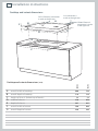
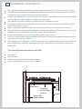
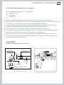
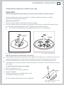
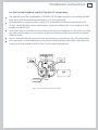
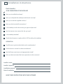
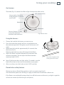
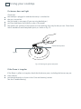
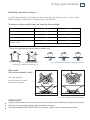
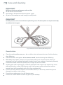
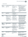
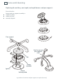
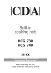
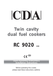
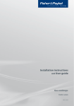
1
Installation instructions
and User guide
Gas-on-glass cooktops
CG604 and CG755 models
GB IE
Contents
Safety and warnings
Installation instructions
Introduction
Using your cooktop
Care and cleaning
Troubleshooting
Warranty and service
Important!
SAVE THESE INSTRUCTIONS
The models shown in this manual may not be available in all markets and are
subject to change at any time. For current details about model and specification
availability in your country, please visit our local website listed on the back cover
or contact your local Fisher & Paykel dealer.
1
2
6
22
23
26
30
31
2
Safety and warnings
WARNING!
Cut Hazard
Beware of sharp edges when handling stainless steel appliances.
Failure to use caution could result in injury or cuts.
WARNING!
Electrical Shock Hazard
Before carrying out any work on the electrical section of the appliance, it must
be disconnected from the mains power supply.
Connection to a good earth wiring system is essential and mandatory.
Failure to follow this advice may result in death or electrical shock.
Important safety precautions
Installation
Read these instructions carefully before installing or using this product.
Please make this information available to the person responsible for installing the product as it
could reduce your installation costs.
This appliance must be installed in accordance with these installation instructions, local gas
fitting regulations, municipal building codes, electrical wiring regulations, and any other relevant
statutory regulations.
This appliance shall only be serviced by authorised personnel.
Always disconnect the cooktop from mains power supply before carrying out any maintenance
operations or repairs.
In the room where the cooktop is installed, there must be enough air to allow the gas to burn
correctly, according to the current local regulations.
Safety and warnings
3
Particular attention shall be given to the relevant requirements regarding ventilation.
This product should not be sealed into the bench with silicone or glue. Doing so will make future
servicing difficult. Fisher & Paykel will not be liable for costs associated with releasing such a
product, nor for repairing damage that may be incurred in doing this.
No combustible material or products should be placed on this product at any time.
Do not spray aerosols in the vicinity of this product while it is in operation.
4
Safety and warnings
WARNING!
Hot Surface Hazard
This appliance becomes hot during use.
Do not touch the cooktop components, burners, trivets/pan supports or the
base when hot.
Before cleaning, turn the burners off and make sure the whole cooktop is cool.
Failure to follow this advice may result in serious injury.
WARNING!
Explosion Hazard
Do not store flammable materials such as gasoline near the cooktop.Do not
spray aerosols near the cooktop during use.
Failure to follow this advice may result in death or serious injury.
WARNING!
Electrical Shock Hazard
Do not cook on a broken or cracked cooktop. If the cooktop surface
should break or crack, turn off the gas supply and switch the appliance off
immediately at the mains power supply (wall switch) and contact a qualified
technician.
Switch off the cooktop at the wall before carrying out cleaning or
maintenance.
Failure to follow this advice may result in death or electrical shock.
Safety and warnings
5
Important safety precautions
Operation
Children, or persons with a disability which limits their ability to use the appliance, should
have a responsible person to instruct them in its use. The instructor should be satisfied that
they can use the appliance without danger to themselves or their surroundings.
If the power supply cable is damaged, it must only be replaced by an authorised person.
Ensure that the electrical connection plug is accessible after installation.
This appliance should be connected to a circuit that incorporates an isolating switch
providing full disconnection from the power supply.
Do not use an asbestos mat or decorative covers between the flame and the saucepan as
this may cause serious damage to your cooktop.
Do not place aluminium foil or plastic dishes on the cooktop burners.
Do not let large saucepans or frying pans overlap the bench as this can deflect heat onto
your benchtop and damage the surface.
Do not let large saucepans, frying pans or woks push any other pans aside. This could make
them unstable or deflect heat onto your benchtop and damage the surface.
Do not use a steam cleaner for cleaning this cooktop.
Saucepan handles may be hot to touch. Ensure saucepan handles do not overhang other
gas burners that are on. Keep handles out of reach of children.
Keep children away from the cooktop when it is in use.
Household appliances are not intended to be played with by children.
Do not stand on this appliance.
Do not place or drop heavy objects on this appliance.
After use, ensure that the knobs are in the off position.
This appliance shall not be used as a space heater.
The use of a gas cooking appliance results in the production of heat and moisture in the
room in which it is installed. Ensure the kitchen is well ventilated. Keep natural ventilation
holes open or install a mechanical ventilation device (mechanical extractor hood).
Prolonged intensive use of the appliance may call for additional ventilation, for example
opening of a window, or more effective ventilation, for example increasing the level of
mechanical ventilation where present.
After having unpacked the appliance, check to ensure that it is not damaged.
In case of doubt, do not use it and consult your supplier or a professionally qualified technician.
Packing elements (i.e. plastic bags, polystyrene foam, nails, packing straps, etc.) should not be
left around within easy reach of children, as these may cause serious injuries.
6
Installation instructions
Cooktop and cutout dimensions
CG755: Electrical connection
is made at the left rear
C
Gas connection is
made at the right rear
A
B
D
CG604: Electrical
connection is made
at the right rear
E
G
F
Cooktop and cutout dimensions (mm)
CG604
CG755
A
B
C
D
E
F
G
overall width of cooktop
600
750
overall depth of cooktop
510
510
54
54
width of chassis
550
670
depth of chassis
467
467
overall width of cutout
560
680
overall depth of cutout
480
480
height of chassis (below top of bench)
Installation instructions
7
Clearances
A
E
B
C
D
B
C
D
E
minimum clearance from rear edge of cutout to:
nearest combustible surface
minimum clearance from glass surface to:
rangehood
minimum clearance from side edges of cutout to:
nearest combustible surface
minimum clearance below top of benchtop to:
combustible surface
nearest non-combustible surface
(eg thermal protection barrier)
minimum clearance from benchtop to:
overhead cabinet not directly above the cooktop
CG755
A
CG604
Clearances (mm)
60
60
650
650
220
235
84
84
84
84
450
450
8
Installation instructions
The appliance may be installed in a suitable room in accordance with the current laws in force.
The appliance is designed and approved for domestic use only and should not be installed in a
commercial, semi-commercial or communal environment.
Installing the appliance in any of the above environments will void the warranty and could affect
any third-party or public liability insurances you may have.
The appliance must be installed in compliance with regulations in force.
Installation technicians must comply with current laws in force concerning ventilation and the
evacuation of exhaust gases.
Always unplug the appliance before carrying out any maintenance operations or repairs.
The walls of the units around the appliance must not be higher than the benchtop and must be
capable of resisting temperatures of 105oC above room temperature.
Do not install the appliance near flammable materials (eg curtains).
You must install a thermal protection barrier between the base of the appliance and the built-in
unit or an oven. See Fig. 1 below.
If the appliance is installed over a built-in oven, the oven should be fitted with a cooling fan and
the two appliances should be connected to the gas and electricity supply with independent
connections.
The thermal protection barrier must be:
Clearance
Thermal
protection
barrier
Space for
connections
Fig. 1 Location of thermal protection barrier
30 mm
removable
heat-resistant
made from low thermal conductivity material
at least 30 mm below the base of the cooktop
Door
Installation instructions
9
Ventilation requirements (all countries except UK)
H min 650 mm
Providing adequate ventilation
The installer must refer to the current local regulations.
Extractor
hood to
The room accommodating the gas cooktop must have
extract steam
adequate natural draught to allow combustion of the gas.
The flow of air must come directly from one or more air vents
made in the outside walls with a free area of at least 100 cm2.
The vents must be positioned close to the floor, preferably
on the opposite side to the gas burners of your cooktop
(as shown in Figs. 2a and 2b). The vents must be designed
in such a way that they cannot be obstructed either from
the inside or the outside.
When it is not possible to provide the necessary vents,
Air vent
the draught may be supplied from an adjacent room,
ventilated in the required manner, provided it is not a
Fig. 2a Ventilation with an extractor hood
bedroom or an area at risk. In this event, the kitchen door
must be opened to allow the draught to enter the room.
Extracting cooking and gas fumes
Important!
This appliance is not connected to a device extracting the
products of gas combustion. Such a device must be installed
and connected in accordance with the installation rules in force.
Take special care to provide adequate room ventilation as well.
To eliminate cooking and gas fumes, extractor hoods
ducted directly to the outside must be installed (Fig. 2a).
If this is not possible, an electric fan installed in an
external wall or window may be used; the fan should have
a capacity to circulate air at an hourly rate of 3 to 5 times
the total volume of the kitchen (Fig. 2b). The fan can only
be installed if the kitchen has suitable vents to allow air to
enter, as described under ‘Providing adequate ventilation’
above.
Electric fan
to extract
steam
Air vent
Fig. 2b Ventilation with an electric fan
10
Installation instructions
Ventilation requirements (United Kingdom only)
The appliance should be installed in a room or space with an air supply in accordance with BS
5440:2 2000.
For rooms with a volume of less than 5 m3, permanent ventilation through a free area of at least
100 cm2 will be required.
For rooms with a volume between 5 m3 and 10 m3, permanent ventilation through a free area of
at least 50 cm2 will be required, unless the room has a door which opens directly to the outside
air, in which case no permanent ventilation is required.
For rooms with a volume greater than 10 m3, no permanent ventilation is required.
Important!
Regardless of room size, all rooms containing the appliance must have direct access to the outside air via an
openable window or equivalent.
Where there are other fuel-burning appliances in the same room, BS 5440-2: 2000 should be
consulted to determine the correct amount of free area ventilation requirements.
The above requirements also allow for use of a gas oven and grill, but you need to consult a
qualified engineer if there are other gas-burning appliances in the same room.
Installation instructions
11
Fastening the cooktop to the bench
Note: if your bench is thicker than 40 mm, recess the underside to between 30 and 40 mm.
S
R
R
REAR
S
SF
S F
FRONT
Seal
Adhesive side
Fig. 3 Preparing the cooktop before installation
A
S
min
R
30 mm
A
Fig. 4 Fastening the cooktop to the bench
S
F
40 mm
FRONT CLAMPS
30 mm
REAR CLAMPS
min
5
30 mm
4
30 mm
3
Turn the cooktop upside down and place it on a soft surface.
Spread the seal around the edges, with the adhesive side facing down.
Mount the supplied front and rear clamps (F and R) and screws (S) onto the cooktop, as shown
(without tightening the screws).
Place the cooktop into the cutout, then tighten the screws to clamp the cooktop securely to the
bench.
Using a sharp cutter or trimmer knife, trim the excess sealing material around the edge of the
cooktop. Take care not to damage the benchtop.
40 mm
1
2
12
Installation instructions
Gas installation requirements
This appliance is adjusted at the factory for use on Natural gas.
To use it on LPG, it will first have to be converted. If the LPG conversion kit is not supplied with
the appliance, contact your nearest Authorised Service Centre.
Installation and service regulations (United Kingdom only)
Important!
This appliance must be installed and serviced only by a suitably qualified and registered person, and in
accordance with the current editions of the following standards and regulations or other locally applicable
regulations:
Gas Safety (Installation and Use) Regulations
Building Regulations
British Standards
Regulations for Electrical Installation
Failure to install the appliance correctly could invalidate any manufacturer’s warranty
and lead to prosecution under the above-quoted regulation.
Additional gas connection requirements (United Kingdom only)
We recommend connecting the appliance to the gas with a flexible hose made to BS5386.
Flexible hoses can be used where the sited ambient temperature of the hose will not exceed
70oC. Any hose used must comply with BS 669, Part 1 and be of the correct construction for the
type of gas being used.
Flexible hoses designed for Natural gas MUST NOT be used for supplying LPG (LPG flexible hoses
can be identified by either a red band or strip on their outer coating).
Installation and service regulations (all countries)
Important!
This appliance must be installed and serviced only by a suitably qualified, registered installer
with technical knowledge of both gas installation and electricity. The installation or service must
comply with the current editions of the applicable standards, regulations, and codes of practice
governing gas and electrical installations.
Failure to install the appliance correctly could invalidate any manufacturer’s warranty.
Installation instructions
13
Connecting the cooktop to the gas supply
The gas connection fitting (Fig. 5) is made up of:
the floating nut
the elbow
the washer.
If using a flexible hose, make sure it does not come into contact with moving parts.
To maintain the minimum 30 mm clearance requirement below the base of the cooktop, the rear
of the chassis is recessed to provide a channel for the appliance inlet pipe.
The gas connection fitting can be turned in the direction required (but never in a vertical or
horizontal position) after loosening the elbow and floating nut connection.
Never attempt to turn the elbow without having first loosened the floating nut.
The supplied washer guarantees a good seal for the gas connection. We recommend that you
replace it on the slightest sign of wear, deformation or imperfection.
After connecting the gas supply, check the piping and connections for leaks as required by
local regulations. The presence of bubbles indicates a leak. Tighten or replace connections as
appropriate, then re-check for leaks.
Important!
Do not use any naked flame to check for leaks.
Floating nut
½” cylindrical
Elbow
Washer
½” G conical
Appliance
inlet
pipe
Rigid pipe or flexible hose
Fig. 5 Gas connection fitting
Fig. 6 Turning the gas connection fitting
14
Installation instructions
When connecting the cooktop to the gas supply with rigid pipes or a flexible
hose (which must comply with BS 669 in the UK), make sure that:
you use rigid pipes or a flexible hose compliant with applicable local regulations. The flexible
hose shall be of the correct construction for the type of gas being used and of the correct size to
maintain the heat output of the appliance
the connection with rigid metal pipes does not cause stress or pressure to the gas piping
the flexible hose is not under tension, twisted, kinked, or too tightly bent, neither while the
cooktop is in use nor while it is being connected or disconnected
the flexible hose is not longer than 2000 mm (or refer to applicable local regulations) and does
not come into contact with sharp edges, corners, or moving parts, as these may cause abrasion.
Use a single flexible hose only; never connect the cooktop with more than one flexible hose
the flexible hose can easily be inspected along its entire length to check its condition; if it has an
expiry date, it should be replaced before that date
if using a flexible hose which is not entirely made of metal, make sure that it does not come into
contact with any part of the cooktop with a surface temperature of 70oC or above
the rigid pipe or flexible hose is replaced if it shows signs of damage
the flexible hose is not subject to excessive heat by direct exposure to flue products or by
contact with hot surfaces
the socket into which the plug of the flexible hose fit is permanently attached to a firmly fixed
gas installation pipe and is positioned so that the hose hangs freely downwards
the plug of the flexible hose is accessible after installation, so that it can be disconnected for
service or removal
you inform the customer that the rigid pipe or flexible hose should not be subjected to
corrosion by cleaning agents.
Installation instructions
15
Leak-testing and flame-testing the cooktop
1
After connecting the gas supply, check the piping and connections for leaks as required by
local regulations. The presence of bubbles indicates a leak. Tighten or replace connections as
appropriate, then re-check for leaks.
Important!
Do not use any naked flame to check for leaks.
2
3
4
5
The operation of the appliance MUST be tested before leaving.
Turn on the gas and light each burner. Check for a well-defined blue flame without any yellow
tipping. If any abnormality is evident, check that the burner cap is located properly and the
injector nipple is aligned correctly.
Check the minimum burner setting by quickly rotating the burner knobs from the maximum
to the minimum position: the flame must not go out. If adjustment is required, see section
‘Adjusting a burner’s minimum gas rate setting’ following.
If satisfactory performance cannot be obtained, check the installation and notify the local gas
supply authority of a gas supply problem, or if it is an appliance problem, our Customer Service
Centre should be called to obtain the nearest authorised Service Agent.
IE
Gas type:
G30/G31
Gas type:
G20
GB
REDUCED
POWER
(HS - kW)
NOMINAL
POWER
(HS - kW)
1,00
1,75
3,00
3,50
Auxiliary (A)
Semi-rapid (SR)
Rapid (R)
Triple ring (TR)
BURNERS
1,50
3,50
Triple ring (TR)
0,45
1,50
0,75
0,45
0,30
0,75
1,75
3,00
Rapid (R)
0,30
REDUCED
POWER
(HS - kW)
Semi-rapid (SR)
1,00
NOMINAL
POWER
(HS - kW)
Auxiliary (A)
BURNERS
Table for the choice of injectors
95
85
65
50
Ø INJECTOR
(1/100 mm)
135 (T)
115 (Y)
97 (Z)
72 (X)
Ø INJECTOR
(1/100 mm)
Cat:
II 2H3+
28-30/37
GAS
PRESSURE
(mbar)
20
GAS
PRESSURE
(mbar)
16
Installation instructions
Installation instructions
17
Converting the cooktop to a different gas type
Important!
Only a suitably qualified and registered person may convert the cooktop to a different gas type.
To convert from one gas type to another, you need to replace the injectors, and then
adjust the minimum gas rate setting.
1
2
Replacing the injectors
Remove the pan supports and burners from the cooktop.
Using a spanner, remove the injectors and replace them with ones suitable for the type of gas
you are converting the cooktop to. See the ‘Table for the choice of injectors’.
The burners are designed so that regulation of primary air is not required.
Injector
Fig. 7 Auxiliary, rapid and semi-rapid burners
Injector
Fig. 8 Triple-ring wok burner
Adjusting a burner’s minimum gas rate setting
Check whether the flame spreads to all burner ports when the burner is lit with the gas valve set
to the minimum position. If some ports do not light, increase the minimum gas rate setting.
Check whether the burner remains lit even when the gas valve is turned quickly from the
maximum to the minimum position. If the burner does not remain lit, increase the minimum gas
rate setting.
1
2
3
4
To adjust the minimum gas rate setting
Make sure the burner is lit.
Turn the knob to the minimum position.
Remove the knob.
Using a screwdriver, turn the adjustment screw
until the flame setting is correct.
Adjustment
screw
For LPG, tighten the adjustment screw completely.
Fig. 9 Adjusting a burner’s minimum gas rate setting
18
Installation instructions
Electrical connection
Important!
This appliance must be earthed.
Installation must be carried out according to the manufacturer’s instructions.
Incorrect installation may cause harm and damage to people, animals or property, for which the
manufacturer accepts no responsibility.
If the installation requires alterations to the domestic wiring system, call a qualified electrician.
The electrician should also check that the socket cable section is suitable for the power drawn by
the appliance. Before carrying out any work on the electrical section of the appliance, it must be
disconnected from the power supply.
The plug must be connected to an earthed socket in compliance with safety standards.
Do not use adapters, reducers, a multi-outlet power board or branching devices when connecting
this appliance to the mains power supply, as doing so can cause overheating and burning.
The appliance must be connected to the mains power supply checking that the voltage
corresponds to the value given in the rating plate and that the electrical cable sections can
withstand the load specified on the plate.
If the appliance is supplied without a plug, fit a standard plug which is suitable for the power
consumed by the appliance.
A suitable isolating switch providing full disconnection from the mains power supply must be
incorporated in the permanent wiring, mounted and positioned to comply with the local wiring
rules and regulations. The switch must be of an approved type and provide a 3 mm air gap
contact separation in all poles in accordance with the local wiring rules. The switch or socket
must be accessible with the appliance installed.
The power supply cable must not touch any hot parts and must be positioned so that it does not
exceed 75°C at any point along its length.
If the power supply cable is damaged, it must be replaced by a cable of the same type. It can only
be replaced by the manufacturer, its Service Agent or a similarly qualified person in order to
avoid a hazard.
As the colours of the wires in the power supply cable of this appliance may not correspond with
the coloured markings identifying the terminals in your plug, proceed as follows:
Colour of power supply cable wire
Green & Yellow
Blue
Brown
Power supply cable section
Type H05V2V2-F, resistant to temperature of up to 90oC
Power supply
230 V~ 50/60 Hz 3 x 0.75 mm2
Colour or mark of plug terminal
“E” (Earth) or green or
“N” (Neutral) or black
“L” (Live) or red
230 V
L1 PE N(L2)
Fig. 10 Connection diagram
Installation instructions
19
For the United Kingdom and the Republic of Ireland only:
The appliance must be connected to a 220-240V~50 Hz supply by means of a suitably earthed
three-pin socket and should be protected by a 3A fuse in the plug.
If the appliance is supplied without a plug, fit a rewireable 13A three-pin plug fitted with a
3A fuse. Should the fuse require replacement, it must be replaced with a fuse rated at 3A and
complying with BS1362.
If the mains plug is unsuitable for the socket at the place of installation or it has to be cut off for
any other reason, make sure you dispose of the removed plug safely to prevent the hazard of
electrical shock.
There is a danger of electrical shock if the removed plug is inserted into any 13A socket outlet.
If the appliance is connected directly to the fixed wiring, a double-pole switch of the electrical
supply must be provided no further than 2 metres from the appliance.
A
Cable clamp
Fig. 11 Connection by a three-pin socket
20
Installation instructions
Final checklist
TO BE COMPLETED BY THE INSTALLER
Have you installed the clamps?
Have you clamped the cooktop to the bench securely?
Have you used the supplied washers?
Have you leak-tested all connections?
Is the cooktop set for the correct gas type and pressure?
Are the injector sizes correct for the gas type?
Is the cooktop earthed?
Check that the power supply cable is NOT touching the cooktop.
OPERATION:
Do all burners ignitie individually and in combination?
Do the burners remain lit when turned down?
Are the flames consistent and appropriately sized?
Have you demonstrated the basic operation to the customer?
Installer’s name:
Installer’s signature:
Installation company:
Date of installation:
LEAVE THESE INSTRUCTIONS WITH THE CUSTOMER
21
22
Introduction
About your new cooktop
Thank you for buying a Fisher & Paykel gas cooktop. Once it is installed and ready to use, you
will want to know everything about it to make sure you get excellent results right from the start.
This guide introduces you to all its special features. We recommend you read the whole guide
before using your new cooktop, for both safety and cooking success.
For more information, visit our local website listed on the back cover.
Before using your new cooktop
Before using your new cooktop, please:
read this user guide, taking special note of the ‘Safety and warnings’ section
ensure the power supply to the cooktop is turned on.
3
2
2
2
4
1
5
10
8
3
2
11
8
Fig.12a Cooktop layout-CG604
1
2
3
4
5
6
Auxiliary burner
Semi-rapid burner
Rapid burner
Triple-ring wok burner
Auxiliary burner knob
Left semi-rapid burner knob
1
6
9
7
5
Fig.12b Cooktop layout-CG755
7
8
9
10
11
Right semi-rapid burner knob
Rapid burner knob
Triple-ring wok burner knob
Rear semi-rapid burner knob
Front semi-rapid burner knob
Using your cooktop
23
Gas burners
The knob (Fig. 13) controls the flow of gas through the safety valve.
Never cook or leave the
knob between maximum
and O (off ).
OFF (closed valve)
Maximum
Minimum
You can choose to cook
at any heat between
minimum and maximum
Fig.13 Burner knob
1
Using the burners
1
2
3
4
Choose the knob for the burner you want to use.
Press the knob down gently and turn it anticlockwise to
the maximum position. The ignitors on all the burners will
spark.
Hold down the knob for approximately 10 seconds after
the burner has lit.
Releasing the knob too soon will extinguish the flame.
Adjust the flame anywhere between the maximum and
minimum positions. Do not adjust the flame between
maximum and O (OFF).
2
Fig. 14 Pressing down then
turning the burner knob
Note: If the burner does not light within 15 seconds, turn the
knob off and wait at least one minute before trying again.
5
After use, always turn the knobs to the O (OFF) position.
Flame failure safety feature
The burners have a flame failure probe as well as an ignitor (see Fig 15).
The flame failure probe cuts off the gas supply to the burner if the flame is blown out.
If the flames are accidentally extinguished, turn off the burner and do not try to light it again for
at least one minute (to allow the gas to disperse).
24
Using your cooktop
If a burner does not light
Check that:
the cooktop is plugged in and the electricity is switched on
the gas is turned on
the gas bottle is not empty (if you are using bottled gas)
you have held down the knob for at least 10 seconds
the ignitors are sparking. If the ignitors are not sparking, they may be dirty or wet. Clean them
with a toothbrush and methylated spirits, as shown in Fig. 15.
Flame failure probe
Ignitor
Fig.15 Cleaning the ignitor and probe
If the flame is irregular
If the flame is yellow or irregular, check that the burner parts, including the burner cap, are:
clean and dry
positioned correctly as shown in the ‘Care and cleaning’ section.
See also ‘Troubleshooting’.
Using your cooktop
25
Matching cookware to burner
Use flat-bottomed pans, and make sure they match the size of the burner, as shown in the
following table. A small pot on a large burner is not efficient.
Diameters of pans which may be used on the cooktop
Burners
Minimum
Maximum
Auxiliary
12 cm
14 cm
Semi-rapid
16 cm
20cm*, 24 cm
Rapid
24 cm
26 cm
Triple-ring wok (five-burner
models only)
26 cm
28 cm
Maximum diameter for woks 36 cm
* Front semi-rapid burner on four burner models only
Fig. 17 Efficient and inefficient saucepan bottoms
Fig. 16 Correct and incorrect
matching of cookware and burner size
Wok stand
(five-burner models only)
The wok stand fits
over the triple-ring wok
burner pan support.
WRONG
CORRECT
Fig. 18 Correct placement of wok stand
Important!
Using a wok without the stand may cause the wok to tip or the wok burner to operate incorrectly.
Do not use the stand for ordinary, flat-bottomed saucepans.
The wok stand MUST BE PLACED ONLY over the pan support for the triple-ring wok burner.
26
Care and cleaning
Important!
Before any cleaning or maintenance, make sure that:
all the burners are turned off
the cooktop is disconnected from the power supply
all parts of the cooktop are cool enough to safely touch.
Important!
For safety reasons, never unscrew the burner plate fixing screws. The burner plates can only be removed by
an authorised service agent.
Fig. 19 Never unscrew the burner plate fixing screws
General advice
Clean the cooktop after every use – do not allow stains to become burnt on. See the cleaning
chart following.
Clean the burners and ignitors at least once a month. See the cleaning chart following.
Once every 3 or 4 years, contact your local Authorised Service Centre and have all the gas
components of your cooktop thoroughly checked, even if your cooktop is functioning correctly.
Do not leave acidic substances (lemon juice, vinegar etc) on the surfaces.
Anything that melts onto the glass surface or food spills with a high sugar content may cause
pitting of the glass surface if left there to cool. Using extreme caution around hot surfaces,
remove these spills immediately with a fish slice or palette knife.
Do not use harsh, abrasive cleaners or unsuitable scourers, as these may scratch the glass or
damage the stainless steel surfaces.
Do not clean cooktop parts in a self-cleaning oven.
Do not use a steam cleaner to clean any part of your cooktop.
Care and cleaning
27
Cleaning chart
What?
Soiling examples
Stainless
steel strip
fingerprints
food stains
How?
1 Wipe with a clean
damp cloth.
2 Dry with a soft, lintfree cloth.
Regular use of a
stainless steel polish
will reduce fingerprints
and other marks
Follow the
manufacturer’s
instructions.
Important!
Never use harsh/abrasive
cleaning agents and scourers
as they will damage the
stainless steel finish.
Chlorine compounds in some
cleaners (eg bleaches) are
corrosive to stainless steel and
may damage its appearance.
The graphics are etched onto
the steel by laser and will not
rub off.
Knobs
fingerprints
food stains
1 Clean with hot
soapy water.
2 Dry thoroughly with
a soft cloth.
Glass
surface
dust
stains left by liquid
spillovers or burnton food
sugar, sugary syrups,
jams and jellies
vegetables and
vegetable water with
a high sugar content
eg peas, sweet corn,
beetroot
1 Remove the pan
supports, burner
caps, and flame
spreaders.
2 Remove any spills or
burnt-on food.
3 Apply ceramic glass
cooktop cleaner.
4 Wipe with a clean,
damp cloth and dry.
Remove stains left by sugary
food or spillovers as soon as
possible. If left to burn on or
cool, they may be difficult to
remove or even permanently
damage the glass surface.
Take extreme care when
working around hot surfaces!
Heavy-duty scourers, some
nylon scourers and harsh/
abrasive cleaning agents
may scratch the glass. Always
read the label to check if your
cleaner or scourer is suitable.
Make sure you replace the
burner parts correctly, as
shown in the drawings
following.
Do not use the burners
without all its parts correctly
in place.
Dry all burner parts
thoroughly before replacing
as even small droplets
of water will affect the
performance of a burner.
Pan
supports,
burner caps
and ring
stains left by liquid
spillovers or burnt-on
food
1 Remove parts, then
soak to remove
stubborn stains,
then wash with hot
soapy water.
2 Rinse, then dry with
a soft cloth.
Flame
spreaders
soiling trapped in
the holes and
notches
1 Use a stiff nylon
brush or a
straightended paper
clip to clear the
holes and notches.
2 Wash with hot soapy
water.
3 Rinse and wipe dry.
Ignitor
food or liquid spillovers Use a toothbrush
on these parts
and methylated spirits
to clean these. See
Fig. 15.
Flame
failure
probe
A dirty or wet ignitor will prevent
the burner from lighting
efficiently.
A dirty probe may prevent the
flame failure device from
working effectively.
28
Care and cleaning
Replacing the auxiliary, semi-rapid, and rapid burners and pan supports
Ensure that the
burner and pan support assembly is:
unable to rotate
stable and level
correctly aligned.
Pan support
Use the correct
pan support
only
Cap
Flame
spreader
Ignitor
Flame
failure probe
Fig. 20 Ensure the burners and pan supports are replaced correctly
Care and cleaning
29
Replacing the triple-ring wok burner and pan support (five-burner models only)
Ensure that the
burner and pan support assembly is:
unable to rotate
stable and level
correctly aligned.
Flame spreader
Ignitor
Use the correct
pan support
only
Flame
failure probe
Cap
Ring
Fig. 21 Ensure the burner and pan support are replaced correctly
30
Troubleshooting
Problem
Possible solutions
A burner does not light
Check the cooktop is plugged in and the electricity is switched on.
Check the gas supply valve is turned on and the supply to the
house is working. You should hear the gas when you turn a burner
on.
If you use bottled gas, check the gas bottle is not empty.
The ignitors may be dirty. Clean them with a toothbrush and
methylated spirits.
The burner parts may not be located properly. Check the assembly
and make sure the burner cap is sitting flat.
My burner flames are
yellow or hard to start
The burner parts may not be located properly. Check the assembly
and make sure the burner cap is sitting flat.
If you use bottled gas, this may indicate you are getting near the
end of the bottle.
Check the burner parts are clean and dry.
The gas pressure may not be at the correct level. Check with your
service person or installer.
Your cooktop may not be set up for the gas you are using. Check
this with your service person or installer.
One of my burners has an
uneven flame
Check the burner parts are clean and dry. Check the burner is
assembled correctly and make sure the burner cap is sitting flat.
The flame goes out at low
settings
The gas supply pressure may be low. Check this with your service
person or installer.
The low setting may have been adjusted incorrectly. Check this
with your service person or installer.
If you use bottled gas, this may indicate you are getting near the
end of the bottle.
My burners do not turn
down much (when running
on bottled gas or LPG)
Your cooktop may not have been adjusted correctly. Check this
with your service person or installer.
The flame tips are very
yellow
Call your service person to service the cooktop.
There are objectionable
odours
Call your service person to service the cooktop.
The flame appears to lift
off the burner
Call your service person to service the cooktop.
There is an electricity
failure
If there is an electricity failure, you can still use your cooktop.
Light the burners by holding a match close to the side of the
burner and turning the knob to the Maximum position. Wait until
the flame is burning evenly before adjusting.
Warranty and service
31
Before you call for service or assistance ...
Check the things you can do yourself. Refer to the installation instructions and your user guide
and check that:
1
2
your product is correctly installed
you are familiar with its normal operation.
If after checking these points you still need assistance, please refer to the Service & Warranty
book for warranty and after-sales service details or contact us through our local website listed on
the back cover.
This cooktop has been designed and constructed in accordance with the following
codes and specifications:
Safety requirements of EEC Directive “Gas” 90/396
- EN 30-1-1
- EN 30-2-1
- EN 437
Safety requirements of EEC Directive “Low voltage” 2006/95:
- EN 60335-1 General Requirements for Domestic electrical appliances
- EN 60335-2-6 Particular Requirements for Domestic electrical cooking appliances
Safety requirements of EEC Directive “EMC” 89/336:
- EN 55014-1, EN 55014-2, EN 61000-3-2, EN 61000-3-3 Electromagnetic Compatibility
Requirements
Requirements of EEC Directive 93/68
Product details
Fisher & Paykel Ltd
Model
Serial no.
Date of purchase
Purchaser
Dealer
Suburb
Town
Country
34
Copyright © Fisher & Paykel 2008. All rights reserved.
The product specifications in this booklet apply to
the specific products and models described at the
date of issue. Under our policy of continuous product
improvement, these specifications may change at any
time. You should therefore check with your Dealer to
ensure this booklet correctly describes the product
currently available.
www.fisherpaykel.co.uk
www.fisherpaykel.ie
GB IE
Gas-on-glass cooktop installation and user guide
Published: 09/2008
F&P Part No. 599575 A
F&P Italy Part No. 1103208 - ß1