1
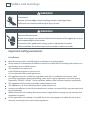
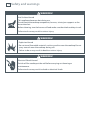
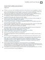
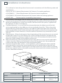
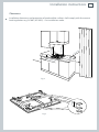
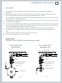
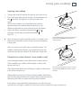
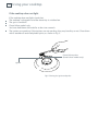
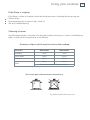
1
Installation instructions
and User guide
Gas cooktops
CG604 models
NZ AU
Contents
1
Safety and warnings
2
Installation instructions
6
Introduction
Using your cooktop
Care and cleaning
Troubleshooting
Warranty and service
Important!
SAVE THESE INSTRUCTIONS
The models shown in this User Guide may not be available in all markets and are
subject to change at any time. For current details about model and specification
availability in your country, please go to our website www.fisherpaykel.com or
contact your local Fisher & Paykel dealer.
16
18
23
27
28
2
Safety and warnings
WARNING!
Cut Hazard
Beware of sharp edges when handling stainless steel appliances.
Failure to use caution could result in injury or cuts.
WARNING!
Electrical Shock Hazard
Before carrying out any work on the electrical section of the appliance, it must
be disconnected from the mains.
Connection to a good earth wiring system is absolutely essential.
Failure to follow this advice may result in death or electrical shock.
Important safety precautions
Installation
Read these instructions carefully before installing or using this product.
Please make this information available to the person responsible for installing the product as it
could reduce your installation costs.
These products are registered:
in New Zealand at www.ess.govt.nz and
in Australia with AGA at www.gas.asn.au.
This appliance must be installed in accordance with these installation instructions, local
gas fitting regulations, municipal building codes, water supply regulations, electrical wiring
regulations, AS5601 / AG 601 - Gas Installations and any other relevant statutory regulations.
This appliance shall only be serviced by authorised personnel.
This appliance is to be installed only by an authorised person.
Incorrect installation, for which the manufacturer accepts no responsibility, may cause personal
injury of damage.
Always disconnect the cooktop from mains power supply before carrying out any maintenance
operations or repairs.
In the room where the cooktop is installed, there must be enough air to allow the gas to burn
correctly, according to the current local regulations.
Safety and warnings
3
Particular attention shall be given to the relevant requirements regarding ventilation.
This product should not be sealed into the bench with silicone or glue. Doing so will make future
servicing difficult. Fisher & Paykel will not be liable for costs associated with releasing such a
product, nor for repairing damage that may be incurred in doing this.
When this product is installed it shall not be used as a space heater, especially if installed in boats
or caravans.
No combustible material or products should be placed on this product at any time.
Do not spray aerosols in the vicinity of this product while it is in operation.
4
Safety and warnings
WARNING!
Hot Surface Hazard
This appliance becomes hot during use.
Do not touch the cooktop components, burners, trivets/pan supports or the
base when hot.
Before cleaning, turn the burners off and make sure the whole cooktop is cool.
Failure to do so may result in serious injury.
WARNING!
Explosion Hazard
Do not store flammable materials such as gasoline near the cooktop.Do not
spray aerosols near the cooktop during use.
Failure to do so may result in death or serious injury.
WARNING!
Electrical Shock Hazard
Switch off the cooktop at the wall before carrying out cleaning or
maintenance.
Failure to do so may result in death or electrical shock
Safety and warnings
5
Important safety precautions
Operation
Children, or persons with a disability which limits their ability to use the appliance, should
have a responsible person to instruct them in its use. The instructor should be satisfied that
they can use the appliance without danger to themselves or their surroundings.
If the electrical supply cord is damaged, it must only be replaced by an authorised person.
Ensure that the electrical connection plug is accessible after installation.
This appliance should be connected to a circuit that incorporates an isolating switch
providing full disconnection from the electricity supply.
Do not use an asbestos mat or decorative covers between the flame and the saucepan as
this may cause serious damage to your cooktop.
Do not place aluminium foil or plastic dishes on the cooktop burners.
Do not let large saucepans or frying pans overlap the bench as this can deflect heat onto
your benchtop and damage the surface.
Do not let large saucepans, frying pans or woks push any other pans aside. This could make
them unstable or deflect heat onto your benchtop and damage the surface.
Do not use a steam cleaner for cleaning this cooktop.
Saucepan handles may be hot to touch. Ensure saucepan handles do not overhang other
gas burners that are on. Keep handles out of reach of children.
Keep children away from the cooktop when it is in use.
Household appliances are not intended to be played with by children
Do not stand or place heavy objects on this appliance.
After use, ensure that the knobs are in off position.
This appliance shall not be used as a space heater, especially if installed in marine craft or
caravans.
The use of a gas cooking appliance results in the production of heat and moisture in the
room in which it is installed. Ensure the kitchen is well ventilated. Keep natural ventilation
holes open or install a mechanical ventilation device (mechanical extractor hood).
Prolonged intensive use of the appliance may call for additional ventilation, for example
opening of a window, or more effective ventilation, for example increasing the level of
mechanical ventilation where present.
After having unpacked the appliance, check to ensure that it is not damaged.
In case of doubt, do not use it and consult your supplier or a professionally qualified technician.
Packing elements (i.e. plastic bags, polystyrene foam, nails, packing straps, etc.) should not be
left around within easy reach of children, as these may cause serious injuries.
Some appliances are supplied with a protective film on steel and aluminium parts. This film
must be removed before using the appliance.
6
Installation instructions
This cooktop has been designed and constructed in accordance with the following codes and
specifications:
AGA101 (AS 4551) Approval Requirements for Domestic Gas cooking appliances
AS/NZS 60335-1 General Requirements for Domestic electrical appliances
AS/NSZ 60335-2-6 Particular Requirements for Domestic electrical cooking appliances
AS/NSZ 1044
Electromagnetic Compatibility Requirements.
The installation shall comply with the dimensions in Figures 1 and 2, bearing in mind that:
A minimum clearance of 20 mm has to be kept between the bottom of the cooking hob and
the top of an appliance or a shelf. To ensure this clearance mount the spacers, supplied with
the appliance, as shown in the figure 3.
Overhead clearances - In no case shall the clearance between the highest part of the hob
and a range hood be less than 600 mm, or for an overhead exhaust fan, 750 mm. Any other
downward facing combustible surface less than 600 mm above the highest part of the hob
shall be protected for the full width and depth of the cooking surface area in accordance with
local regulations in force. However, in no case shall this clearance to any surface be less than
450 mm.
Side clearances - Where the dimension from the periphery of the nearest burner to any vertical
combustible surface is less than 200 mm, the surface shall be protected in accordance with
with local regulations in force to a height of not less than 150 mm above the hob for the full
dimension (width or depth) of the cooking surface area.
Where the dimensions from the periphery of the nearest burner to any vertical combustible
surface is less than 200 mm, the horizontal surface shall be greater than 10 mm below the
surface of the hob, or the horizontal surface requirement above.
Protection of combustible surfaces - Local regulations in force specify that where required
protection shall ensure that the surface temperature of the combustible surface does not
exceed 65 °C above ambient. The fixing of 5 mm thick ceramic tiles to the surface or attaching
fire resistant material to the surface and covering with sheet metal with minimum thickness of
0.4 mm should be satisfactory.
580
500
34
200
Fig. 1
560
480
0
–2
0
–2
Cooktop dimensions
Cut-out dimensions
Width
580 mm
Depth
500 mm
Depth below mounting surface
60
34 mm
Width
560 mm
0
–2
Depth
480 mm
0
–2
Installation instructions
Clearances
450 mm
750 mm
Installation clearances and protection of combustible surfaces shall comply with the current
local regulations e.g. AG 601 (AS 5601) - Gas Installations code.
200 m
m
min
500 mm
20 mm
Fig. 2
Fig. 3
in
mm
m
60
7
8
Installation instructions
Fastening the installation brackets (fig. 4)
Each cooktop is provided with an installation kit including brackets and screws for fastening
the top to fixture panels from 2 to 4 cm thick.
Turn the cooktop upside down and fasten the brackets “F and R” to the appropriate socket
holes, without tightening the screws “B” for the moment.
Make sure that the brackets are fastened as shown in figure 4.
Fastening the cooktop (fig. 4)
Spread the sealing material “C” out along the fixture hole, making sure that the junctions
overlap at the corners.
Insert the cook top into the hole and position it correctly.
Adjust the position of the brackets “F and R” and tighten screws “B” to block the cooker top
firmly in position.
With a sharp cutter or trimmer knife trim the excess sealing material around the edge of the
cooktop.
R
Gas inlet pipe
R
F
NT
FRO
F
Front side
Rear side
C
C
B
Fig. 4
F
40 mm min.
R
B
20 mm min.
40 mm min.
20 mm min.
0
–2
0
–2
Installation instructions
9
Gas supply
The connection must be executed by an authorised person according to the relevant
standards.
Before connecting the appliance to the gas main, mount the brass conical adaptor onto the
gas inlet pipe, upon which the gasket has been placed (figures 5 and 6).
Conical adaptor and gasket are supplied with the appliance (packed with conversion kit for use
with Natural gas or Universal LPG).
This appliance is suitable for use with Natural Gas or Universal LPG. (Check the “gas type” sticker
attached to the appliance).
For Natural Gas models the gas supply is connected to the pressure regulator which is supplied
with the appliance (fig. 5). Adjust the regulator to obtain a test point pressure of 1 kPa with the
two semi-rapid burners operating at the maximum.
For Universal LPG models the gas supply is connected to the test point adaptor which is
supplied with the appliance (fig. 6) and ensure that the supply pressure is regulated to 2.75
kPa.
Do NOT force the ”elbow“ rotation prior to loosening nut.
Do NOT over tighten the nut at the ”elbow“.
Important!
This appliance IS NOT SUITABLE for installation with a hose assembly.
Gas connection for
UNIVERSAL LPG
Gas connection for
NATURAL GAS
Gas inlet pipe
Test
point
Gasket
Gasket
Brass conical adaptor
(Thread tight: use
suitable seal)
Brass conical adaptor
(Thread tight: use
suitable seal)
Test point adaptor
Gas regulator
Test
point
Fig. 5
Fig. 6
10
1
Installation instructions
After connecting the gas supply, check the piping and connections for leaks using a soap and
water solution. The presence of bubbles indicates a leak, tighten or replace connections as
appropriate.
Important!
Do not use any naked flame to check for leaks.
2
3
4
5
6
7
The operation of the appliance MUST be tested before leaving.
Adjust the test point pressure or supply pressure to the value which is appropriate for the gas
type.
Turn on the appliance gas controls and light each burner. Check for a well defined blue flame
without any yellow tipping. If any abnormality is evident then check that the burner cap is
located properly and the injector nipple is aligned correctly.
Check the minimum burner setting by quickly rotating the gas control knob from the maximum
to the minimum position, the flame must not go out. If adjustment is required carry out the
“minimum burner setting adjustment” section following.
If satisfactory performance cannot be obtained, the installer shall check the installation and
notify the local gas supply authority for a gas supply problem, or if it is an appliance problem,
our Customer Service Centre should be called to obtain the nearest authorized Service Agent.
Where the appliance data plate cannot be easily read with the appliance in the installed position
the duplicate data plate must be attached to adjacent surface and the duplicate Universal LPG
conversion label should also be included where a Universal LPG conversion has been completed.
Table for the choice of the injectors
Natural Gas
Universal LPG
1.0
2.75
Test point Pressure [kPa]
BURNER
Auxiliary
Injector
Orifice Dia.
Gas
Consumption
Injector
Orifice Dia.
Gas
Consumption
[mm]
[MJ/h]
[mm]
[MJ/h]
0.85
3.60
0.53
3.60
Semi-rapid
1.12
6.30
0.70
6.30
Rapid
1.45
10.30
0.91
10.80
Wok
1.65
13.00
0.95
11.90
Installation instructions
11
Conversion procedure (to convert to Universal LPG) replacing the injectors.
Important!
The conversion procedure must be carried out only by an authorised person.
This appliance is suitable for use with Natural gas or Universal LPG (check the “gas type” sticker
attached to the appliance). See the “Table for the choice of injectors” for the nominal gas consumption and injector size details.
To replace the injectors proceed as follows:
Remove pan supports and burners from the cooktop.
Using a spanner, remove the injector J (figs. 7, 8) and replace it with one according to the gas
type (see “Table for the choice of injectors”).
Affix to the appliance the warning label stating that the cooktop has been converted for use
with Universal LPG (supplied with the Universal LPG conversion kit.).
A second Universal LPG conversion label should also be affixed to an adjacent surface along
with the duplicate data plate.
Important!
If the cooktop is suitable for use with Natural gas and must be converted for use with Universal
LPG, before connecting to gas main remove the appliance gas regulator and replace with test
point adaptor (see fig. 5, 6)
If the cooktop is suitable for use with Universal LPG and must be converted for use with Natural
gas, before connecting to the gas main remove the appliance test point adaptor and replace
with gas regulator (see figs. 5, 6).
Note: Gas regulator and test point adaptor are supplied with the appliance (packed with
conversion kit)
The burners are designed so that regulation of primary air is not required.
J
Fig. 7
J
Fig. 8
12
Installation instructions
Minimum burner setting adjustment
When changing from one type of gas to another, the minimum tap output must also be correct, considering that in this position the flame must be about 4 mm long and must remain
lit even when the knob is turned sharply from the maximum to the minimum position.
The adjustment is performed with the burner lit, as follows:
Turn the knob to the minimum position.
Remove the tap knob.
On gas valves provided with adjustment screw in the centre of the shaft (fig. 9)
Using a screwdriver with max. diameter 3 mm, turn the screw inside the tap until the correct
setting is obtained.
On gas valves provided with adjustment screw on the valve body (fig. 10)
Turn the screw “A” to the correct setting with a screwdriver.
In models with a gas-lighter incorporated into the knob, turn screw “A” via the hole in the
microswitch.
For Universal LPG, tighten the adjustment screw completely.
Lubricating the gas taps
If a gas tap is difficult to turn, disassemble it, clean it carefully with petrol and spread a little
high-temperature-resistant grease on it.
A
Fig. 9
Fig. 10
Installation instructions
13
Important!
Installation must be carried out according to the manufacturer's instructions.
Incorrect installation may cause harm and damage to people, animals or property, for which
the manufacturer accepts no responsibility.
Before carrying out any work on the electrical section of the appliance, it must be
disconnected from the mains.
Connection to a good earth wiring system is absolutely essential.
The manufacturer accepts no responsibility for any inconvenience caused by failure to
comply with this rule.
Electrical requirements
The appliance must be connected to the mains checking that the voltage corresponds to the
value given in the rating plate and that the electrical cable sections can withstand the load
specified on the plate.
The plug must be connected to an earthed socket in compliance with safety standards.
If the appliance is supplied without plug, fit a standard plug which is suitable for the power
consumed by the appliance.
The wires in the power cable are coloured in accordance with the following code:
Green/Yellow = Earth, Blue = Neutral, Brown = Active.
If the colours of the wires in the power cable to the appliance do not correspond with the
coloured markings identifying the terminals in the junction terminal, proceed as follows:
1
2
3
The wire which is coloured green and yellow must be connected to the terminal marked E (Earth)
or coloured Green.
The wire which is coloured blue must be connected to the terminal marked N (Neutral) or
coloured Black.
The wire which is coloured brown must be connected to the terminal marked L (Live) or A
(Active) or coloured Red.
A suitable disconnection switch is incorporated in the permanent wiring, mounted and positioned to
comply with the local wiring rules and regulations. The switch must be of an approved type installed
in the fixed wiring and provide a 3 mm air gap contact separation in all poles in accordance with the
local wiring rules.
In Australia and New Zealand, a switch of the approved type with a 3 mm air gap must be installed in
the active (phase) conductor of the fixed wiring.
The power supply cable must not touch the hot parts and must be positioned so that it does not
exceed 50°C above ambient.
Once the appliance has been installed, the switch or socket must always be accessible.
If the supply cord is damaged it must be replaced by the manufacturer or its Service Agent or a
similarly qualified person in order to avoid a hazard.
N.B. The connection of the appliance to earth is mandatory.
If the installation requires alterations to the domestic electrical system call a qualified
electrician.
He should also check that the socket cable section is suitable for the power drawn by the
appliance.
14
Installation instructions
Important!
Replacing the power cord must be done by a qualified electrician in accordance with the instructions
supplied by the manufacturer and in compliance with established electrical regulations.
Electric diagrams key
PA
A
M
CA
Ignition switch
Ignition coil
Terminal block
Spark electrode
CA
CA
CA
CA
M
N
L
A
PA
PA
PA
PA
Fig. 11
15
16
Introduction
About your new cooktop
Thank you for buying a Fisher & Paykel gas cooktop. Once it is installed and ready to use, you
will want to know everything about it to make sure you get excellent results right from the start.
This guide introduces you to all its special features. We recommend you read the whole guide
before using your new cooktop, for both safety and cooking success.
For more information, go to www.fisherpaykel.com
Before using your new cooktop
Before using your new cooktop, please:
Read this user guide, taking special note of the ‘Safety and warnings’ section.
Plug the cooktop into the electricity supply and turn it on so the electronic ignition will work.
Introduction
2
17
2
5
3
Fig.1 CG604 with rapid burner
(no flame failure safety feature)
2
1
2
2
2
5
4
5
4
1
Fig.2b CG604 with wok burner
(no flame failure safety feature)
Fig.2a CG604 with wok burner
( with flame failure safety feature)
1
2
3
4
5
Auxiliary burner
Semi-rapid burner
Rapid burner
Wok burner
Cooktop controls
1
18
Using your cooktop
Gas burners
The knob (Fig. 3) controls the flow of gas through the safety tap.
OFF
=
closed valve
=
maximum aperture or flow
=
minimum aperture or flow
You can choose to cook at any heat between
and OFF.
and
, but never between
Fig. 3a Burner knob and symbols (models without flame failure safety feature)
Fig. 3b Burner knob and symbols (models with flame failure safety feature)
Using your cooktop
19
Lighting the cooktop
1
2
3
Choose the control knob for the burner you want to use.
Press the knob down gently and turn it anticlockwise to
the position. The ignitors on all the burners will
spark.
Flame failure models only: Hold down the knob for
approximately ten seconds after the burner has lit.
Releasing the knob too soon will extinguish the flame.
Adjust the flame anywhere between the and
positions. Do not adjust the flame between
and OFF.
Note: If the burner does not light within 15 seconds, turn
the control knob off and wait at least one minute before
trying again.
1
2
Fig. 4a Pushing then turning the control
knob (models without flame failure
safety feature)
After use, always turn the knobs to the off position. For
models without flame failure, you should also close the
cock valve on the gas bottle or the main gas supply line.
Flame failure safety feature (some models only)
Some cooktop models have a flame failure safety device.
These models have a flame failure probe as well as the
ignitor (see Fig 5).
The flame failure probe cuts off the gas supply to the burner
if the flame is blown out.
Fig. 4b Pushing then turning the control
knob (models with flame failure safety
feature)
When lighting the burner on flame failure models, hold down
the knob for approximately ten seconds after the burner has lit.
Releasing the knob too soon will extinguish the flame.
If the flames are accidentally extinguished, turn off the burner
and do not try to light it again for at least one minute (to allow the gas to disperse).
20
Using your cooktop
If the cooktop does not light
If the cooktop does not light, check that:
The cooktop is plugged in and the electricity is switched on.
The gas is turned on.
Flame failure models only:
You have held down the knob for at least ten seconds.
The ignitors are sparking. If the ignitors are not sparking, they may be dirty or wet. Clean them
with a toothbrush and methylated spirits, as shown in Fig. 5.
Flame failure probe
(flame failure models only)
Ignitor
Fig.5 Cleaning the ignitor and probe
Using your cooktop
21
If the flame is irregular
If the flame is yellow or irregular, check that the burner parts, including the burner cap, are:
Clean and dry.
Positioned correctly as shown in figs. 9 and 10.
See also ‘Troubleshooting’.
Choosing a burner
Use flat-bottomed pans, and make sure that they match your burner, as shown in the following
table. A small pot on a large burner is not efficient.
Diameters of pans which may be used on the cooktop
Burners
Minimum
Maximum
Auxiliary
12 cm
14 cm
Semi-rapid
16 cm
24 cm
Rapid
24 cm
26 cm
26 cm
28 cm
Wok
Maximum diameter for woks: 36 cm
Do not use pans with concave or convex bases
Fig. 6 Efficient and inefficient pot sizes.
22
Using your cooktop
Wok stand - models fitted with wok burner only (fig. 8)
The wok stand fits over the pan support for the wok burner.
Important!
Using a wok without the stand may cause the burner to operate incorrectly.
Do not use the stand for ordinary, flat-bottomed saucepans.
The wok stand MUST BE PLACED ONLY over the pan support for the wok burner.
WRONG
Fig. 7 Incorrect use of wok on burner
Important!
The cooktop becomes very hot during operation.
Keep children well out of reach.
CORRECT
Fig. 8 Correct use of wok on wok stand over burner
Care and cleaning
23
General advice
Maintenance Period
Description
Daily
Clean gas cooktop as per following
instructions.
Monthly
Remove all burner parts, and clean using a
non-abrasive detergent. Rinse in cold water,
dry thoroughly, and replace.
Clean the ignitor and probe carefully, using
a toothbrush and methylated spirits. (Note:
probe is only on flame-failure models)
Every 3-4 years
Contact your local authorized gas Service
Agent to perform a thorough check on all gas
components on the gas cooker.
Before you begin cleaning you must ensure that the cooktop is switched off.
Clean the cooktop regularly – do not let stains become burnt on.
Allow the appliance to cool down before cleaning.
Avoid leaving acidic substances (lemon juice, vinegar etc.) on the surfaces.
The control knobs may be removed for cleaning but care should be taken not to damage the
seal.
Do not clean cooktop parts in a self-cleaning oven.
Do not use steam cleaners because the moisture could get inside the appliance making it
dangerous.
For stubborn stains, see the ‘Cleaning chart’.
Enamelled parts
Clean the enamelled parts with a sponge and soapy water only or other non-abrasive
products.
Dry preferably with a microfibre or soft cloth.
If acidic substances such as lemon juice, tomato sauce, vinegar etc. are left in contact with the
enamel for a long time they will damage the surface.
Stainless steel surfaces
Stainless steel parts should be rinsed with water and dried with a microfibre or soft cloth.
Dry thoroughly to avoid leaving water marks. For extra shine on stainless steel, use a stainless
steel polish.
Clean brushed stainless steel in the direction of the grain.
For persistent dirt, use specific non-abrasive products available commercially or a little hot
vinegar.
Note: regular use could cause discolouring around the burners, because of the high flame
temperature.
24
Care and cleaning
Burners and pan supports
You can remove and clean these parts with hot soapy water or other appropriate products - see
‘Cleaning chart’.
After cleaning, check that the burners and their flame spreaders are dry before replacing
correctly.
It is very important to check that the burner flame spreader and the cap have been correctly
positioned. Failure to do so can cause serious problems.
Note: To avoid damage to the electric ignition do not try to light the cooktop when the burners
are not in place.
Replacing the burners
It is very important to check that the burner flame spreader “F” and the cap “C” have been
correctly positioned (see fig. 9).
Failure to do so can cause serious problems.
Check that the ignitor S (figs. 9 and 11) is always clean to ensure trouble-free sparking.
In the models with the flame failure safety device, check that the probe T (figs. 9 and 11) next to
each burner is always clean to ensure correct operation of the safety valves.
Both the ignitor (S) and probe (T) must be very carefully cleaned using a toothbrush and
methylated spirits.
C
F
T*
S
Fig. 9 Correct line-up of the burner parts
* Models with flame failure device only
Fig. 10 Replacing the burner cap
Care and cleaning
25
Replacing the wok burner
To replace the wok burner:
1
Fit the burner ring to the housing as shown by the arrow in fig. 11. Make sure the burner is not
able to rotate (fig. 12)
S
T
Fig. 11 Fitting the burner ring to the housing.
A
B
Fig. 13 Incorrect and correct
positioning of cap and ring
Fig. 12. Correct positioning of cap and ring
26
Care and cleaning
Cleaning chart
Cooktop part
Trivets/pan
supports, burner
caps
Cleaning
Important
Hot soapy water and nylon scourer.
Soap removeable parts in a solution
of biological clothes-washing
detergent.
Mild abrasive cream cleaners.
Fume-free or heavy-duty oven cleaners
(follow manufacturer’s instructions).
Always allow cooktop parts to
cool completely before cleaning
them.
Burner parts
Hot soapy water.
To clear the holes use a stiff nylon
brush or wire eg straight-ended paper
clip.
Mild abrasive cream cleaners.
Reassemble the burner parts
correctly.
Control knobs
Hot soapy water and a soft cloth.
Stainless steel base
Soak stains under a hot soapy cloth,
rinse and dry thoroughly.
Hard water spots can be removed with
household white vinegar.
Non-abrasive stainless steel cleaners.
Regular use of a stainless steel polish
will reduce fingerprints and other
marks.
Heavy soiling can be removed with
fume-free or heavy-duty oven cleaner
(follow manufacturer’s instructions).
Always apply minimal pressure
with abrasive cleaners.
Clean spills regularly before they
become burnt on.
Never use harsh/abrasive
cleaning agents as they will
damage the stainless steel
finish.
Chlorine or chlorine compounds
in some cleaners are corrosive to
stainless steel and may damage
the appearance of your cooktop.
Check the label on the cleaner
before using.
The graphics are etched onto
the steel by laser and will not
rub off.
Enamel base
Use soft cloth or no-abrasive sponge
and sopay water. Do not use abrasive
products.
Clean spills regularly before they
become burnt on.
Ignitors
Toothbrush and methylated spirits.
Probe (in
models with flame
failure safety
valves)
Toothbrush and methylated spirits.
A dirty or wet ignitor will
prevent the burner lighting
efficiently.
A dirty probe may
prevent the safety valve from
working effectively.
Troubleshooting
27
Troubleshooting chart
Problem
Possible solutions
My cooktop does not light
Check the cooktop is plugged in and the electricity is switched on.
Check the gas supply valve is turned on and the supply to the
house is working. You should hear the gas when you turn a burner
on.
The ignitors may be dirty. Clean them with a toothbrush and
methylated spirits.
The burner parts may not be located properly. Check the assembly
and make sure the burner cap is sitting flat.
My burner flames are
yellow or hard to start
The burner parts may not be located properly. Check the assembly
and make sure the burner cap is sitting flat.
If you use bottled gas this may indicate you are getting near the
end of the bottle.
Check the burner parts are clean and dry.
The gas pressure may not be at the correct level. Check with your
service person or installer.
Your cooktop may not be set up for the gas you are using. Check
this with your service person or installer.
One of my burners has an
uneven flame
Check the burner parts are clean and dry. Check the assembly and
make sure the burner cap is sitting flat.
The flame goes out at low
settings
The gas supply pressure may be low. Check this with your service
person or installer.
The low setting may have been adjusted incorrectly. Check this
with your service person or installer.
My burners do not turn
down much (when running
on bottled gas or LPG)
Your cooktop may not have been adjusted correctly. Check this
with your service person or installer.
The flame tips are very
yellow
Call your service person to service the cooktop.
There are objectionable
odours
Call your service person to service the cooktop.
The flame appears to lift
off the burner
Call your service person to service the cooktop.
There is an electricity
failure
If there is an electricity failure, you can still use your cooktop.
Light the burners by holding a match close to the side of the
burner and turning the control knob to the High position. Wait
until the flame is burning evenly before adjusting.
28
Warranty and service
Before you call for service or assistance ...
Check the things you can do yourself. Refer to the installation instructions and your user guide
and check that:
1
2
Your product is correctly installed.
You are familiar with its normal operation.
If after checking these points you still need assistance, please refer to the Service & Warranty
book for warranty and after-sales service details or contact us through our website:
www.fisherpaykel.com
Product details
Fisher & Paykel Ltd
Model
Serial no.
Date of purchase
Purchaser
Dealer
Suburb
Town
Country
30
Copyright © Fisher & Paykel 2007. All rights reserved.
The product specifications in this booklet apply to
the specific products and models described at the
date of issue. Under our policy of continuous product
improvement, these specifications may change at any
time. You should therefore check with your Dealer to
ensure this booklet correctly describes the product
currently available.
www.fisherpaykel.com
NZ AU
Gas cooktop installation and user guide
Published: 11/2007
F&P Part No. 599371 C
Elba Part No. 1102964 - ß4