1
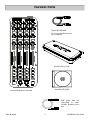
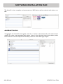
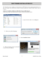
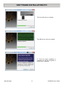
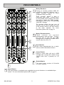
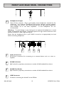
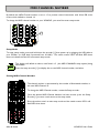
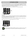
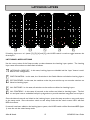
USER GUIDE
Publication AP8509
Allen & Heath
1
XONE:K2 User Guide
Limited One Year Warranty
This product is warranted to be free from defects in materials or
workmanship for period of one year from the date of purchase by the
original owner.
To ensure a high level of performance and reliability for which this
equipment has been designed and manufactured, read this User Guide
before operating. In the event of a failure, notify and return the
defective unit to ALLEN & HEATH Limited or its authorised agent as
soon as possible for repair under warranty subject to the following
conditions
Conditions Of Warranty
The equipment has been installed and operated in accordance with the
instructions in this User Guide.
The equipment has not been subject to misuse either intended or
accidental, neglect, or alteration other than as described in the User
Guide or Service Manual, or approved by ALLEN & HEATH.
Any necessary adjustment, alteration or repair has been carried out by
ALLEN & HEATH or its authorised agent.
This warranty does not cover fader wear and tear.
The defective unit is to be returned carriage prepaid to ALLEN &
HEATH or its authorised agent with proof of purchase.
Units returned should be packed to avoid transit damage.
In certain territories the terms may vary. Check with your ALLEN &
HEATH agent for any additional warranty which may apply.
This product complies with the European Electro magnetic
Compatibility directives 89/336/EEC & 92/31/EEC and the
European Low Voltage Directives 73/23/EEC & 93/68/EEC.
This product has been tested to EN55103 Parts 1 & 2 1996 for use in
Environments E1, E2, E3, and E4 to demonstrate compliance with the
protection requirements in the European EMC directive 89/336/EEC.
During some tests the specified performance figures of the product were
affected. This is considered permissible and the product has been passed as
acceptable for its intended use. Allen & Heath has a strict policy of
ensuring all products are tested to the latest safety and EMC standards.
Customers requiring more information about EMC and safety issues can
contact Allen & Heath.
XONE:K2 User Guide AP8509 Issue 2
Copyright © 2011 Allen & Heath Limited. All rights reserved
Allen & Heath Limited
Kernick Industrial Estate, Penryn, Cornwall, TR10 9LU, UK
http://www.allen-heath.com http://www.xone.co.uk
Allen & Heath
2
XONE:K2 User Guide
PACKED ITEMS
Type A-B USB Lead
To connect the Xone:K2 to
your computer.
Xone:K2 Carry Case
Xone:K2 CD-ROM
Xone:K2 Software Controller
RJ45 patch lead for
connecting to other
X:LINK enabled products
Allen & Heath
3
XONE:K2 User Guide
CONTENTS
Congratulations on purchasing the Allen & Heath Xone:K2 software
controller and audio interface. To ensure that you get the maximum
benefit from the unit please spare a few minutes familiarizing yourself with
the controls and setup procedures outlined in this user guide. For further
information please refer to the additional information available on our web
site, or contact our technical support team.
To register your Xone product please visit www.allen-heath.co.uk and, in
the ’Support’ tab, follow the ‘Register Your Product’ link.
Warranty .............................................
Packed Items.......................................
Product Overview .............................
Software Installation Mac .................
Software Installation PC ...................
MIDI Controls ....................................
Front and Rear Panel Connectors .
MIDI Channel Number.....................
Latching Layers ...................................
MIDI Implementation Send ..............
MIDI Implementation Return ..........
MIDI Note Implementation .............
The X:LINK Protocol .......................
Application Examples
Single Setup (Phones Only) ........
Single Setup (Phones and Mix) ...
Single Setup (External Mixer) .....
Dual Setup (Phones Only) ..........
Dual Setup (Phones And Mix) ....
Dual Setup (External Mixer).......
Setup with a DB series Mixer ....
Specifications ......................................
Registration Card ..............................
Allen & Heath
4
2
3
5
6
7
9
10
11
12
14
17
19
21
22
23
24
25
26
27
28
29
29
XONE:K2 User Guide
PRODUCT OVERVIEW
The XONE:K2 is a software controller and audio interface designed to work with all DAW
applications that implement MIDI. The main features of the Xone:K2 are:
•
•
•
•
•
•
•
•
•
52 hardware controls providing up to 171 MIDI control commands across three layers
Customisable Latching Layers system
Back lit switches with individually accessible tri-colour LED illumination
Four-channel 48kHz 16-bit internal soundcard
Carry case that doubles as a stand is included with the product
USB Bus Powered
X:LINK
Light plastic base with steel front panel
Flat board construction but still employing A&H ‘nutted pots’ construction principle
MIDI Interface
The MIDI interface of the Xone:K2 can be customised by the user. The unit can be left in ‘Open
Architecture (Latching Layers Off) Mode’ or set to ‘Latching Layers Mode’. The blocks of control
surface components that are linked to the Latching Layers can be configured by the user.
Audio Interface
The Xone:K2 has an internal four-channel16-bit soundcard that can operate at 44.1 and 48kHz. All
four channels run from the PC to the Xone:K2 and are configured as follows (the labelling is from the
perspective of a DAW):
Soundcard Output 1
Soundcard Output 2
Soundcard Output 3
Soundcard Output 4
-
Headphones Left
Headphones Right
Master Out Left
Master Out Right
X:LINK
It is possible to link two Xone:K2 units together using the X:LINK protocol. The provided RJ45 cable
is used for power and data transfer from one unit to another—this releases one USB port if a second
Xone:K2 is being used for control only.
X:LINK does not transfer audio between the units, so if units are to have their audio aggregated then
two USB ports will be necessary.
Allen & Heath
5
XONE:K2 User Guide
SOFTWARE INSTALLATION MAC
The Xone:K2 is class compliant and enumerates as a MIDI device and four-channel audio device on a
Mac.
AGGREGATE AUDIO
To aggregate two Xone:K2 units together, click the ‘+’ button in the bottom left of the audio devices
window to create a new aggregate audio device. Next, in the right hand side of the window, select
both instances of the K2 and you will essentially create one device with eight outputs.
Allen & Heath
6
XONE:K2 User Guide
SOFTWARE INSTALLATION PC
The Xone:K2 is class compliant and enumerates as a MIDI device and two-channel audio device on a
PC. To benefit from the full four-channels of audio provided, the Xone:K2 ASIO Driver must be
installed.
Software Installation (Windows 2000, XP, Vista and Windows 7)
Follow the procedure described below to install the USB audio and MIDI drivers:
1—Open the Drivers folder and run Setup.exe
2— Select your preferred language
3— Select Install the driver
4— When prompted, connect the Xone:K2
to the PC with the USB lead.
Allen & Heath
7
XONE:K2 User Guide
SOFTWARE INSTALLATION PC
The Xone:K2 will now initialise.
The USB drivers will now initialise.
5— Once the driver installation is
complete you will be prompted to
reboot your computer.
Allen & Heath
8
XONE:K2 User Guide
MIDI CONTROLS
1
1
2
3
2
4
6
Rotary Potentiometers
These controls ar e standar d
potentiometers with end stops. Turning a
pot from left to right will send MIDI
messages with a unique CC number and a
control value from 0 to 127.
3
Pot Switches
Each rotary potentiometer has a switch
with tri-colour illumination below it.
4
Linear Faders
Moving a linear fader will send a MIDI
message with a unique CC number and a
control value from 0 (bottom) to 127
(top).
5
Switch Matrix
The switch matrix consists of 16 back-lit
tri-colour switches.
5
6
Rotary Encoders
Turning an encoder produces MIDI CC
(continuous controller) messages with a
unique controller number in two’s
compliment binary encoding
These encoders feature a built in
momentary push switch. Pressing down
on the encoder knob activates the switch
and sends a “Note On” MIDI message,
releasing the switch sends a corresponding
“Note Off” message.
The window below the top row of
encoders can be used to display the state
of the encoder switch in the same manner
as the other switches. For more
information please refer to page 16.
Layer Button
The Layer button is completely user assignable but can also function as an embedded layer
button. For more information please refer to page 12.
Allen & Heath
9
XONE:K2 User Guide
FRONT AND REAR PANEL CONNECTORS
1
1
Headphones Output
Stereo 3.5mm mini-jack. Plug in good quality stereo headphones intended for DJ
monitoring. Use closed-ear headphones that provide maximum acoustic isolation
when cueing your sources. We recommend that you use high quality headphones
rated between 30 to 100 ohms impedance.
8 ohm headphones are not
recommended.
Warning ! To avoid damage to your hearing do not operate the headphones or sound
system at excessively high volume. Continued exposure to high volume sound can cause
frequency selective or wide range hearing loss.
Ensure that the headphone level in your DAW is turned to an appropriately low level
before connecting headphones.
1
2
3
4
1
Audio Connectors
RCA Phono connectors for connecting to an external device such as a mixer or
amplifier.
2
X:LINK In Socket
RJ45 socket for proprietary connection to another X:LINK enabled Xone device.
3
X:LINK Out Socket
RJ45 socket for proprietary connection to another X:LINK enabled Xone device.
4
USB Connector
Socket for connecting the Xone:K2 to the PC/Mac.
Allen & Heath
10
XONE:K2 User Guide
MIDI CHANNEL NUMBER
By default the MIDI Channel number is set to 15 to prevent control interaction with Xone DB series
mixers which default to channel 16.
To change the MIDI channel number on your XONE:K2, you must first enter setup mode.
1
Setup Mode
To enter setup mode, press and hold down the encoder [1] then power up by plugging the USB cable to
your PC/Mac, (or RJ45 lead if powered from X-LINK). The switch matrix LED’s will flash RED three
times to indicate that the K2 has entered setup mode.
The display will default as above, with Switch ‘A’ (the MIDI CHANNEL setup option) being
illuminated.
Press the setup encoder [1] to display the current MIDI channel number; see below.
Setting MIDI Channel Number
The channel number is represented by the number of illuminated switches; in
this case MIDI Channel 14.
To change the MIDI Channel number, rotate the Setup encoder.
Once the desired MIDI Channel Number has been chosen, press the Setup
Encoder [1] to store it and return to the setup mode.
Press the amber switch to exit setup mode and the switch matrix LED’s will
flash RED three times.
Allen & Heath
11
XONE:K2 User Guide
LATCHING LAYERS
Latching Layers’ provide embedded layer control via the ‘LAYER’ button on the Xone:K2. If Latching Layers are on, the LAYER switch is used to toggle between the RED, AMBER then GREEN layers. From this,
if the LAYER switch is RED, any switch used on this layer will illuminate RED; if the layer switch is
AMBER, then any switch used on this layer will illuminate AMBER etc.
To change the Latching Layers system on your XONE:K2, you must first enter setup mode.
1
Setup Mode
To enter setup mode, press and hold down the encoder [1] then power up by plugging the USB cable to
your PC/Mac, (or RJ45 lead if powered from X-LINK). The switch matrix LED’s will flash RED three
times to indicate that the K2 has entered setup mode.
The display will default as above, with switch ‘A’ (the MIDI CHANNEL setup option) being illuminated.
Rotate the setup encoder [1] clockwise to illuminate switch ‘B’; see below.
Once switch ‘B’ (the LATCHING LAYERS setup option) is illuminated, press the setup
encoder [1] to display which components are attached to the latching layers; see overleaf.
Allen & Heath
12
XONE:K2 User Guide
LATCHING LAYERS
1
2
3
4
5
If Latching Layers are ‘on’ (states [2], [3], [4] and [5]), the LAYER switch is used to toggle between the
three layers.
LATCHING LAYER OPTIONS
Use the rotary action of the Setup encoder to select between the Latching Layer options. The Latching
Layer states shown above are described as follows:
1
LATCHING LAYERS OFF - In this state, Latching Layers are disabled and the ‘Layer’ button is available for user configuration.
2
SWITCH MATRIX - In this state, the 16 switches in the Switch Matrix are linked to Latching Layers.
3
POT SWITCHES - In this state, the switches under the pots and the top row encoder switches are
linked to Latching layers.
4
ALL SWITCHES - In this state, all switches on the surface are linked to Latching Layers.
5
ALL CONTROLS - In this state, all controls on the surface are linked to Latching Layers. The faders and pots have an embedded soft pick up algorithm to provide seamless integration across layers.
Once the desired controls are linked to the Latching Layers, press the setup encoder to store and return
to the setup mode. Press the amber switch to exit setup mode and the switch matrix LED’s will flash
RED three times.
If controls have been added to the latching layers system, the LAYER switch will be illuminated RED (layer
1) once the unit has exited setup mode.
Allen & Heath
13
XONE:K2 User Guide
MIDI IMPLEMENTATION SEND
▼E3
▼F3
▼F#3
▼G3
◄►CC0
◄►CC1
◄►CC2
◄►CC3
▼E6
▼F6
▼F#6
▼G6
◄►CC22
◄►CC23
◄►CC24
◄►CC25
▼E9
▼F9
▼F#9
▼G9
◄►CC44
◄►CC45
◄►CC46
◄►CC47
◄►CC4
◄►CC5
◄►CC6
◄►CC7
◄►CC26
◄►CC27
◄►CC28
◄►CC29
◄►CC48
◄►CC49
◄►CC50
◄►CC51
■ C3
■ C#3
■ D3
■ D#3(Eb3)
■ C6
■ C#6
■ D6
■ D#6(Eb6)
■ C9
■ C#9
■ D9
■ D#9(Eb9)
◄►CC8
◄►CC9
◄►CC10
◄►CC11
◄►CC30
◄►CC31
◄►CC32
◄►CC33
◄►CC52
◄►CC53
◄►CC54
◄►CC55
■ G#2
■ A2
■ A#2(Bb2)
■ B2
■ G#5
■ A5
■ A#2(Bb5)
■ B5
■ G#8
■ A8
■ A#2(Bb8)
■ B8
Allen & Heath
14
LATCHING LAYERS OFF
LATCHING LAYERS ON
LATCHING LAYERS OFF
LATCHING LAYERS ON
LATCHING LAYERS OFF
LATCHING LAYERS ON
LATCHING LAYERS OFF
LATCHING LAYERS ON
LATCHING LAYERS OFF
LATCHING LAYERS ON
XONE:K2 User Guide
MIDI IMPLEMENTATION SEND
◄►CC12
◄►CC13
◄►CC14
◄►CC15
◄►CC34
◄►CC35
◄►CC36
◄►CC37
◄►CC56
◄►CC57
◄►CC58
◄►CC59
■ E2
■ F2
■ F#2
■ G2
■ E5
■ F5
■ F#5
■ G5
■ E8
■ F8
■ F#8
■ G8
◄►CC16
◄►CC17
◄►CC18
◄►CC19
◄►CC38
◄►CC39
◄►CC40
◄►CC41
◄►CC60
◄►CC61
◄►CC62
◄►CC63
■ C2
■ C#2
■ D2
■ D#2(Eb2)
■ C5
■ C#5
■ D5
■ D#5(Eb5)
■ C8
■ C#8
■ D8
■ D#8(Eb8)
■ G#1
■ A1
■ A#1(Bb1)
■ B1
■ G#4
■ A4
■ A#4(Bb4)
■ B4
■ G#7
■ A7
■ A#7(Bb7)
■ B7
Allen & Heath
15
LATCHING LAYERS OFF
LATCHING LAYERS ON
LATCHING LAYERS OFF
LATCHING LAYERS ON
LATCHING LAYERS OFF
LATCHING LAYERS ON
LATCHING LAYERS OFF
LATCHING LAYERS ON
LATCHING LAYERS OFF
LATCHING LAYERS ON
XONE:K2 User Guide
MIDI IMPLEMENTATION SEND
■ E1
■ F1
■ F#1
■ G1
■ E4
■ F4
■ F#4
■ G4
■ E7
■ F7
■ F#7
■ G7
■ C1
■ C#1
■ D1
■ D#1(Eb1)
■ C4
■ C#4
■ D4
■ D#4(Eb4)
■ C7
■ C#7
■ D7
■ D#7(Eb7)
■ C0
▼ C#0
▼ D0
■ D#0(Eb0)
◄►CC20
◄►CC21
■ E0
▼ F0
◄►CC42
■ G#0
▼ A0
◄►CC68
Allen & Heath
▼ F#0
LATCHING LAYERS OFF
LATCHING LAYERS ON
LATCHING LAYERS OFF
LATCHING LAYERS ON
LATCHING LAYERS OFF
■ G0
◄►CC43
▼ A#0(Bb0) ■ B0
LATCHING LAYERS ON
◄►CC69
16
XONE:K2 User Guide
MIDI IMPLEMENTATION RETURN
▼E3
▼F3
▼F#3
▼G3
▼E6
▼F6
▼F#6
▼G6
▼E9
▼F9
▼F#9
▼G9
■ C3
■ C#3
■ D3
■ D#3(Eb3)
■ C6
■ C#6
■ D6
■ D#6(Eb6)
■ C9
■ C#9
■ D9
■ D#9(Eb9)
■ G#2
■ A2
■ A#2(Bb2)
■ B2
■ G#5
■ A5
■ A#5(Bb5)
■ B5
■ G#8
■ A8
■ A#8(Bb8)
■ B8
■ E2
■ F2
■ F#2
■ G2
■ E5
■ F5
■ F#5
■ G5
■ E8
■ F8
■ F#8
■ G8
Allen & Heath
17
XONE:K2 User Guide
MIDI IMPLEMENTATION RETURN
■ C2
■ C#2
■ D2
■ D#2(Eb2)
■ C5
■ C#5
■ D5
■ D#5(Eb5)
■ C8
■ C#8
■ D8
■ D#8(Eb8)
■ G#1
■ A1
■ A#1(Bb1)
■ B1
■ G#4
■ A4
■ A#4(Bb4)
■ B4
■ G#7
■ A7
■ A#7(Bb7)
■ B7
■ E1
■ F1
■ F#1
■ G1
■ E4
■ F4
■ F#4
■ G4
■ E7
■ F7
■ F#7
■ G7
■ C1
■ C#1
■ D1
■ D#1(Eb1)
■ C4
■ C#4
■ D4
■ D#4(Eb4)
■ C7
■ C#7
■ D7
■ D#7(Eb7)
■ C0
■ D#0(Eb0)
■ E0
■ G0
■ G#0
■ B0
Allen & Heath
18
XONE:K2 User Guide
MIDI NOTE IMPLEMENTATION TABLE
DEC HEX NOTE
DECIMAL HEX NOTE
DECIMAL HEX NOTE
0
00
C-1
24
18
C1
48
30
C3
1
01
C#-1
25
19
C#1
49
31
C#3
2
02
D-1
26
1A
D1
50
32
D3
3
03
D#-1
27
1B
D#1
51
33
D#3
4
04
E-1
28
1C
E1
52
34
E3
5
05
F-1
29
1D
F1
53
35
F3
6
06
F#-1
30
1E
F#1
54
36
F#3
7
07
G-1
31
1F
G1
55
37
G3
8
08
G#-1
32
20
G#1
56
38
G#3
9
09
A-1
33
21
A1
57
39
A3
10
0A
A#-1
34
22
A#1
58
3A
A#3
11
0B
B-1
35
23
B1
59
3B
B3
12
0C
C0
36
24
C2
60
3C
C4
13
0D
C#0
37
25
C#2
61
3D
C#4
14
0E
D0
38
26
D2
62
3E
D4
15
0F
D#0
39
27
D#2
63
3F
D#4
16
10
E0
40
28
E2
64
40
E4
17
11
F0
41
29
F2
65
41
F4
18
12
F#0
42
2A
F#2
66
42
F#4
19
13
G0
43
2B
G2
67
43
G4
20
14
G#0
44
2C
G#2
68
44
G#4
21
15
A0
45
2D
A2
69
45
A4
22
16
A#0
46
2E
A#2
70
46
A#4
23
17
B0
47
2F
B2
71
47
B4
Allen & Heath
19
XONE:K2 User Guide
MIDI NOTE IMPLEMENTATION TABLE
DECIMAL HEX NOTE
DECIMAL HEX NOTE
DECIMAL HEX NOTE
72
48
C5
96
60
C7
120
78
C9
73
49
C#5
97
61
C#7
121
79
C#9
74
4A
D5
98
62
D7
122
7A
D9
75
4B
D#5
99
63
D#7
123
7B
D#9
76
4C
E5
100
64
E7
124
7C
E9
77
4D
F5
101
65
F7
125
7D
F9
78
4E
F#5
102
66
F#7
126
7E
F#9
79
4F
G5
103
67
G7
127
7F
G9
80
50
G#5
104
68
G#7
81
51
A5
105
69
A7
82
52
A#5
106
6A
A#7
83
53
B5
107
6B
B7
84
54
C6
108
6C
C8
85
55
C#6
109
6D
C#8
86
56
D6
110
6E
D8
87
57
D#6
111
6F
D#8
88
58
E6
112
70
E8
89
59
F6
113
71
F8
90
5A
F#6
114
72
F#8
91
5B
G6
115
73
G8
92
5C
G#6
116
74
G#8
93
5D
A6
117
75
A8
94
5E
A#6
118
76
A#8
95
5F
B6
119
77
B8
Allen & Heath
20
XONE:K2 User Guide
THE X:LINK PROTOCOL
The X:LINK protocol is a proprietary Allen and Heath protocol for connection between X:LINK
enabled products.
XONE:K2 X:LINK
In the case of the XONE:K2, X:LINK provides power and MIDI data transfer between two units.
NOTE: X:LINK does not include the transfer of audio.
Use the provided RJ45 cable to link the OUT connection on one unit to the IN connection of the
other. The unit wired to the IN connection should be the unit that is connected to the PC/Mac (see
below).
In order for the units to work independently of each other, the MIDI channel numbers must be different. For information on setting the MIDI channel number please see Page 11.
Allen & Heath
21
XONE:K2 User Guide
APPLICATION EXAMPLES
SINGLE SETUP (PHONES ONLY)
The above diagram shows a basic setup using one Xone:K2 (front and rear panels are both shown).
In this application the XONE:K2 is being used with headphones only.
PC DRIVER TYPE
In this particular application, as only the headphones are in use, it is possible to use the WDM
(Windows Device Manager) driver or the supplied ASIO driver. The WDM driver will default to
Soundcard Output 1-2 which feeds the headphones.
MAC
The XONE:K2 will appear as a device with four outputs. iTunes will default to Soundcard Outputs
1-2 which feeds the headphones.
SOUNDCARD MAPPING
PC WDM:
In DAW application, set Master Output to Soundcard Output 1-2
PC ASIO:
In DAW application, set Master Output to Soundcard Output 1-2
MAC:
In DAW application, set Master Output to Soundcard Output 1-2
Allen & Heath
22
XONE:K2 User Guide
APPLICATION EXAMPLES
SINGLE SETUP (PHONES AND MIX)
The above diagram shows a basic setup using one Xone:K2 (front and rear panels are both shown).
In this application, the XONE:K2 Master output is wired to a speaker system.
PC DRIVER TYPE
In this particular application, as the Master Output and the headphones are in use, the ASIO driver
must be employed.
MAC
The XONE:K2 is Class Compliant and does not need a specific driver.
SOUNDCARD MAPPING
PC ASIO:
In DAW application, set Monitor (or Cue) Output to Soundcard Output 1-2 and
Master (Mix) Output to Soundcard Output 3-4
MAC:
In DAW application, set Monitor (or Cue) Output to Soundcard Output 1-2 and
Master
Allen & Heath
23
XONE:K2 User Guide
APPLICATION EXAMPLES
SINGLE SETUP (EXTERNAL MIXER)
The diagram shows a setup using one XONE:K2 and a twochannel analogue mixer. The front and rear panels of the
XONE:K2 are shown, joined by the dashed line.
In this configuration, the XONE:K2 Master Output is
connected to one channel on the mixer using RCA cables.
The XONE:K2 Headphone Output is connected to the other channel on the mixer using a 3.5mm jack to dual RCA
lead.
PC DRIVER TYPE
In this particular application both Master and Headphone
outputs are required so the ASIO driver must be used.
MAC
The XONE:K2 is Class Compliant and does not need a specific driver.
P
R
O
T U R N T A B L I S T
D J
M I
X E
R
SOUNDCARD MAPPING
Your chosen DAW needs to be set to External Mixing Mode to allow for individual deck outputs.
Selection of this mode will differ depending upon the DAW used. Please refer to the Help files within your DAW for setup information.
PC ASIO:
In DAW application, set one Deck Output to Soundcard Output 1-2 and the other
Deck Output to Soundcard Output 3-4
MAC:
In DAW application, set one Deck Output to Soundcard Output 1-2 and the other
Deck Output to Soundcard Output 3-4
MIXER CONNECTIONS
The mixer will drive the main PA system and headphones.
Allen & Heath
24
XONE:K2 User Guide
APPLICATION EXAMPLES
DUAL SETUP (PHONES ONLY)
The above diagram shows a setup using two Xone:K2s. The front and rear panels are shown on the
’Master’ unit, joined by the dashed line.
In this configuration, the XONE:K2’s are linked together using the X:LINK bus. This gives twice the
amount of control but still only utilises one USB port.
For more information on the X:LINK setup see THE X:LINK PROTOCOL on Page 18.
PC DRIVER TYPE
In this particular application, as only the headphones are in use, it is possible to use the WDM
(Windows Device Manager) driver or the supplied ASIO driver. The WDM driver will default to
Soundcard Output 1-2 which feeds the headphones.
MAC
The XONE:K2 will appear as a device with four outputs. iTunes will default to Soundcard Outputs
1-2 which feeds the headphones.
SOUNDCARD MAPPING
PC WDM:
In DAW application, set Master Output to Soundcard Output 1-2
PC ASIO:
In DAW application, set Master Output to Soundcard Output 1-2
MAC:
In DAW application, set Master Output to Soundcard Output 1-2
Allen & Heath
25
XONE:K2 User Guide
APPLICATION EXAMPLES
DUAL SETUP (PHONES AND MIX)
The above diagram shows a setup using two Xone:K2s. The front and rear panels are shown on the
’Master’ unit, joined by the dashed line.
In this configuration, the XONE:K2’s are linked together using the X:LINK bus. This gives twice the
amount of control but still only utilises one USB port.
The XONE:K2 Master output is wired to a speaker system.
For more information on the X:LINK setup see THE X:LINK PROTOCOL on Page 18.
PC DRIVER TYPE
In this particular application, as the Master Output and the headphones are in use, the ASIO driver
must be used.
MAC
The XONE:K2 is Class Compliant and does not need a specific driver.
SOUNDCARD MAPPING
PC ASIO:
In DAW application, set Monitor (or Cue) Output to Soundcard Output 1-2 and
Master (Mix) Output to Soundcard Output 3-4
MAC:
In DAW application, set Monitor (or Cue) Output to Soundcard Output 1-2 and
Master (Mix) Output to Soundcard Output 3-4
Allen & Heath
26
XONE:K2 User Guide
APPLICATION EXAMPLES
DUAL SETUP (EXTERNAL MIXER)
The diagram shows a setup using two Xone:K2s and a fourchannel analogue mixer. The front and rear panels of the
XONE:K2’s are shown, joined by the dashed line.
In this configuration, the first XONE:K2 Headphone Output
is connected to channel one on the mixer using a 3.5mm
jack to dual RCA lead. The Master Output of this
XONE:K2 is connected to channel two on the mixer using
RCA cables.
The Master Output on the second XONE:K2 is connected
to channel three on the mixer using RCA cables.
The Headphone Output of this XONE:K2 is connected to
channel four on the mixer using a 3.5mm jack to dual RCA
lead.
PC DRIVER TYPE
+
In this particular application both Master and Headphone
outputs are required so the ASIO driver must be used.
MAC
The XONE:K2 is Class Compliant and does not need a specific driver.
AGGRERATING AUDIO DEVICES
This application uses two XONE:K2’s which BOTH need to
be plugged to the Mac/PC via USB. In order for the DAW
application to see 8 (four stereo) outputs, the soundcards
of the two XONE:K2’s must be ‘joined’ together.
PC: To do this on a PC, a third-party application must be used.
MAC: The joining of the two XONE:K2’s on a Mac can be achieved by using the in-built Aggregate
Device Editor—see Page 6.
SOUNDCARD MAPPING
Your chosen DAW needs to be set to External Mixing Mode to allow for individual deck outputs. In
the DAW application route Deck Outputs to Soundcard Outputs accordingly. This may involve
some trial and error to determine which outputs are coming from which XONE:K2.
Allen & Heath
27
XONE:K2 User Guide
APPLICATION EXAMPLES
CONNECTING TO A DB SERIES MIXER
The diagram shows a setup using two Xone:K2s and a XONE DB Series mixer.
In this configuration, the XONE:K2 units are connected via their X:LINK sockets. The OUT connection
of the K2 on the left is connected to the IN connection of the K2 on the right. The OUT connection of
the K2 on the right is connected to the X:LINK socket on the XONE DB Series mixer.
In this configuration, power to the two Xone K2 units is supplied over X:LINK. The DB Series mixer
acts as a MIDI hub for the two Xone K2 units and hence their MIDI Channel numbers must be different
to each other AND the mixer.
The Xone K2 units will not be seen in software as MIDI devices in their own right, and so they will need
to be addressed through the DM mixer using channel numbers to separate the messages they send and
receive.
Allen & Heath
28
XONE:K2 User Guide
SPECIFICATIONS
Dimensions and Weights
Xone:K2
Carry Case
Packed
Width
135 mm(5.3”)
170 mm(6.7”)
185 mm(7.3”)
Height
30 mm(1.2”)
70 mm(2.8”)
78 mm(3”)
Depth
358 mm(14”)
392 mm(15.4”)
426 mm(16.8”)
Weight
1.0kg (2.2lbs)
0.4kg (0.9lbs)
1.5kg (3.3lbs)
Frequency Response 44.1kHz
20Hz to 20kHz +0/–0.4 dB
THD + N
0.01% typical
Maximum Output Level
+6 dBu
Dynamic Range Output
96 dB
Registering your product
Thank you for buying the Allen & Heath Xone:K2 software controller and audio interface. We hope
that you are happy with it and that you enjoy many years of faithful service with it.
Please go to www.allen-heath.com/register.asp and register your product’s serial number and your
details. By registering with us and becoming an official Registered User, you will ensure that any warranty claim you might make is actioned quickly and with the minimum delay.
Alternatively, you may either copy or cut off this section of the page, fill in the details, and return it by
mail to:
Allen & Heath Ltd, Kernick Industrial Estate, Penryn, Cornwall TR10 9LU, UK
Allen & Heath
29
XONE:K2 User Guide
Allen & Heath
30
XONE:K2 User Guide