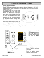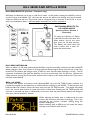
1
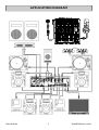
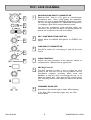
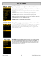
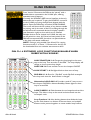
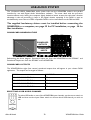
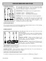
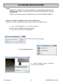
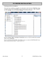
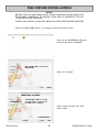
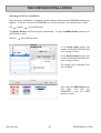
USER GUIDE
Publication AP7977
Issue 3
Allen & Heath
XONE:DB4 User Guide
Limited One Year Manufacturers Warranty
This product is warranted to be free from defects in materials or workmanship for period of one year from the date
of purchase by the original owner.
To ensure a high level of performance and reliability for which this equipment has been designed and manufactured,
read this User Guide before operating.
In the event of a failure, notify and return the defective unit to the place of purchase.
If this is not possible then please contact the authorised ALLEN & HEATH distributor or agent in your country as
soon as possible for repair under warranty subject to the following conditions.
Conditions of Warranty
The equipment has been installed and operated in accordance with the instructions in this User Guide.
The equipment has not been subject to misuse either intended or accidental, neglect, or alteration other than as
described in the User Guide or Service Manual, or approved by ALLEN & HEATH.
Any necessary adjustment, alteration or repair has been carried out by an authorised ALLEN & HEATH distributor or
agent.
This warranty does not cover fader wear and tear.
The defective unit is to be returned carriage prepaid to the place of purchase, an authorised ALLEN & HEATH distributor or agent with proof of purchase.
Please discuss this with the distributor or the agent before shipping.
If the unit is to be repaired in a different country to that of its purchase the repair may take longer than normal,
whilst the warranty is confirmed and parts are sourced.
Units returned should be packed to avoid transit damage.
In certain territories the terms may vary. Check with your ALLEN & HEATH distributor or agent for any additional
warranty which may apply.
If further assistance is required please contact Allen & Heath Ltd.
IMPORTANT- PLEASE READ CAREFULLY:
By using this Allen & Heath product and the software within it, you agree to be bound
by the terms of the relevant End User Licence Agreement (EULA), a copy of which can
be found on the Allen & Heath website in the product's pages. You agree to be bound
by the terms of the EULA by installing, copying, or otherwise using the software.
This product complies with the European Electromagnetic Compatibility directive 2004/108/EC
and the European Low Voltage Directive 2006/95/EC.
This product has been tested to EN55103 Parts 1 & 2 1996 for use in Environments E1, E2, E3, and E4 to
demonstrate compliance with the protection requirements in the European EMC directive 2004/108/EC.
During some tests the specified performance figures of the product were affected. This is considered
permissible and the product has been passed as acceptable for its intended use. Allen & Heath has a strict
policy of ensuring all products are tested to the latest safety and EMC standards. Customers requiring more
information about EMC and safety issues can contact Allen & Heath.
NOTE: Any changes or modifications to the console not approved by Allen & Heath could
void the compliance of the console and therefore the users authority to operate it.
XONE:DB4 User Guide AP7977
Copyright © 2010 Allen & Heath Limited. All rights reserved
Allen & Heath Limited
Kernick Industrial Estate, Penryn, Cornwall, TR10 9LU, UK
http://www.allen-heath.com http://www.XONE.co.uk
Allen & Heath
2
XONE:DB4 User Guide
PACKED ITEMS
Check that you have received the following:
USB
Safety Sheet.
Important ! Read this sheet
before starting.
Retain for future reference.
XONE:DB4 resource
CD-ROM.
XONE:DB4 mixer.
X-LINK Blanking Plug.
Mains Lead.
Check that the correct
mains plug is fitted.
Type A-B USB Lead.
To connect the XONE:DB4
to your computer.
Allen & Heath
Ensure the supplied
blanking plug is always
fitted when not using the
X-Link port. This prevents
damage to the socket pins
which could be caused by
accidental insertion of the
USB lead.
Carry Case.
Custom Allen & Heath protective soft bag for the
XONE:DB4.
NOTE Always pack the mixer
with the rear connector at the
handle end to prevent damage
if the bag is dropped heavily.
Spare knobs.
3
XONE:DB4 User Guide
PANEL DRAWINGS
USB
Allen & Heath
4
XONE:DB4 User Guide
APPLICATION DIAGRAM
Allen & Heath
5
XONE:DB4 User Guide
INTRODUCTION TO THE XONE:DB4
Congratulations on the purchase of your new XONE:DB4
The XONE:DB4 is a ground-breaking mixer featuring studio quality effects and performance
features that blur the boundary between DJ’ing and live production. Every feature has been
meticulously researched with a view to providing you, the DJ, with the ultimate creative tool.
The DB4’s quad FX core is based on the Allen & Heath iLive pro-touring console, but with FX
algorithms further developed for BPM conscious parameters and tight spectral control. Many of
the FX are new and unique to the DB4, and have been specifically designed to perfectly fit the DJ
environment.
All the loops and FX are automatically synchronised to the tempo of the song, so it is very easy
to build some amazing grooves and soundscapes without the problems of latency, low fidelity
and general hassle often associated with using software and laptops.
With the flexible input matrix, any audio source can be selected on any or all of the channels;
this allows for different processing to be applied to the same track on separate channels, or a
phrase sampled in the looper on one channel can be added to the mix later in the track.
The XONE:DB4 is more than a mixer with an effects unit; many parameters of each effect can
be altered and, along with the built in library of effects, this means that the scope for audio
manipulation is almost unlimited, allowing you to develop a totally unique sound in your mixes.
It is also perfectly at home in your production studio, where it can be used as a stereo multichannel effects processor, digitally inserted into your chosen DAW, using the flexible routing
options available on the built in 16 channel USB2.0 soundcard.
The XONE:DB4 is designed to be intuitive and easy to use. However, it is worth spending time
reading this manual to ensure you get the maximum from it.
We have had a lot of fun designing the DB4, and we are sure you will have even more fun using
it.
Best wishes
The XONE:DB4 design team
For the latest information and firmware for your DB4, please visit our website:
www.xone.co.uk/db4
And for the latest product and artist news please visit the Allen & Heath Xone blog:
http://xoneblog.allen-heath.com
Allen & Heath
6
XONE:DB4 User Guide
CONTENTS
To ensure that you get the maximum benefit from your XONE:DB4
please spare a few minutes familiarising yourself with the controls and
setup procedures outlined in this user guide. For further information
please refer to the additional content available on our web site, or contact
our technical support team.
http://www.XONE.co.uk
Warranty .............................................
Packed Items ......................................
Panel Drawings ..................................
Application Diagram .........................
Introduction to the DB4 ..................
Mic/Line Channel...............................
Music Channels .................................
Filter System.......................................
Master Section ...................................
The Input Matrix ...............................
The Music Channel EQ Section .....
The Looper Section ..........................
The Channel FX Section ..................
Configuring the Channel FX ...........
Loading alternative FX .....................
The FX Display and Focus ...............
Kill Send and Delay Millisecond ....
BPM Engines .......................................
Internal MIDI Clock/MIDI channel.
Mixer Setup Menu .............................
XLINK Pairing ....................................
Firmware Updating ...........................
USB Audio System.............................
PC Driver Installation .......................
Mac Driver Installation .....................
MIDI Control .....................................
MIDI Control Messages ...................
Digital In/Out and X-Link ................
Specifications ......................................
Registration Card ..............................
Allen & Heath
2
3
4
5
6
8
10
12
13
15
16
17
18
19
21
22
23
24
25
26
30
31
32
35
38
41
42
45
46
48
7
XONE:DB4 User Guide
MIC / LINE CHANNEL
1
1
2
3
4
2
3
5
6
4
5
6
Allen & Heath
MICROPHONE INPUT CONNECTOR
Balanced XLR. Plug in a DJ, guest or announcement
microphone here. Use a good quality low impedance
dynamic mic such as those specifically designed for vocals.
Do not use high impedance or unbalanced microphones,
or condenser types which require phantom power.
Use the best professional grade balanced cables and
connectors you can afford, as these are typically subject to
intense use and abuse in the club environment.
MIC / LINE SELECTOR SWITCH
Selects either the MONO Microphone or STEREO Line
inputs
LINE INPUT CONNECTOR
Dual RCA sockets for connecting an external line level
source.
GAIN CONTROL
Adjusts the input sensitivity of the Mic/Line channel to
compensate for different source signal levels.
MIC EQ Controls
The MIC equaliser provides a tool to adjust the tonal
quality of the sound to correct source problems such as
microphone response, proximity effect, noise and
feedback, to help the voice cut through the mix, or to
adjust the overall ‘feel’. Start with the EQ controls set to
their mid (flat) position, then adjust to achieve the desired
sound.
CHANNEL PEAK LED
Illuminates if the channel signal is within 3dB of clipping.
If the Peak LED continuously lights turn the Gain
control down.
8
XONE:DB4 User Guide
MIC / LINE CHANNEL
7
8
9
10
7
8
9
CHANNEL CUE SWITCH
Press the Cue switch to listen to the channel pre-fade signal
in the headphones and view its level on the main meters.
The backlit switch lights red when selected. Press the
switch again to deselect cue.
CHANNEL LEVEL CONTROL
Sets the level of the channel signal in the main mix.
CHANNEL ON SWITCH
Turns the channel on, allowing the channel signal to
be routed to the main mix. This feature is very
useful if a microphone is being used as it can be
switched in and out of the mix.
MIX / CH1 SWITCH
Selects where the channel output will be routed:
MIX - Routes the signal directly to the mix
CH1 - Routes the signal to the input of Channel 1
If the switch is set to CH1, the ‘MIC’ LED will illuminate in
Channel 1, overriding the matrix input to that channel.
This will enable loops and effects to be applied to the
microphone input.
From Version 2 firmware, this control will override the
Analogue 1 input of all four channels, allowing the Mic
input to be routed to any, or all of the channels.
The MIC LED flashes continuously when the MIX/CH1
switch is activated, and will also will flash the Matrix 1
LEDs if they are assigned to Analogue.
10
Allen & Heath
9
XONE:DB4 User Guide
MUSIC CHANNEL
1
1
2
3
4
2
3
4
5
5
6
8
6
7
9
7
8
9
Allen & Heath
MATRIX INPUT SELECTOR
Please refer to Page 15 for further information
on how to use this feature.
INPUT TRIM
Amplifies or attenuates the input signal by up to
±10dB. On firmware versions above V1.00 this
is increased to +/-20dB.
INPUT PEAK LED
Illuminates if input signal is within 3dB of
clipping. If this happens lower the Trim level.
This Peak indicator is separate from the channel
meter and displays peak input level, not output.
EQ SECTION
Configured as either Three band EQ or HighPass/Low-Pass filter depending on switch
position. Please refer to Page 16 for further
details on this feature.
LOOP RECORDER
Records and automatically loops input source
when activated. Display shows loop length, and
beat detection activity. Please refer to Page17
for further details on this feature.
FX TYPE SELECT BUTTONS
Selects one of the five basic effects types. Each
selection overrides the previous one. Buttons
will illuminate green to show effect selected or
orange when channel is in focus. Please refer to
Page 18 for further details on this feature.
FX SELECT
Press to move focus to channel. If the channel
has focus then press to open FX library Please
refer to Page 18 for further details on this
feature.
FX EXPRESSION CONTROL
Changes one parameter of selected FX, e.g.
regeneration if delay selected. Please refer to
Page 18 for further details on this feature.
FX WET/DRY CONTROL
The WET/DRY control sets the level of the
effect from no effect (DRY) when fully
anticlockwise to maximum effect (WET) when
fully clockwise. Please refer to Page 18 for
further details on this feature.
10
XONE:DB4 User Guide
MUSIC CHANNEL
10
11
12
FILTER ASSIGN SWITCH
Set the 3-position switch to its mid position to
route the signal direct to the mix, or to its left
or right positions to route the signal to Filter-1
or Filter-2 respectively. See page 12 for more
information on the filter system.
X-FADE ASSIGN SWITCH
Set the 3-position switch to its mid position to
route the signal direct to the mix, or to its left
or right positions to route the signal to
Crossfade-X or Crossfade-Y respectively.
CHANNEL CUE SWITCH
Press the cue switch to listen to the channel pre
-fade signal in the headphones and see its level
on the main meters. The button will illuminate
when selected.
Press the switch to deselect cue. The switches
are interlocked; pressing another one turns off
the previous selection.
Multiple cueing may be achieved in one of two
ways:
1.
Pressing two or more cues simultaneously.
2.
Holding down an active cue allows
momentary activation of any other cue
when pressed.
Disable AutoCue - refer to Page27 for
details.
3.
10
11
12
13
CHANNEL METER
Displays the pre-fader channel signal level.
The channel level control should be set so that
the channel meter averages around ‘0’, with
loudest peaks no higher than ‘+6’. Turn down
the Trim control if the PK! indicator lights.
NOTE: If the EQ and FX are configured to be
Post Fader (see page19) the actual channel signal
level fed to the mix may be higher or lower than
indicated on the meter.
13
14
14
Allen & Heath
CHANNEL FADER
A high quality, smooth travel, dual-rail fader
adjusts the channel signal level from fully off to
fully on.
11
XONE:DB4 User Guide
FILTERS
The XONE:DB4 is equipped with a dual, swept filter system, that emulates the analogue filters that
have been a key feature on most XONE products. The filters can be used as a mix tool, or to create
dynamic effects. On initial power up, or after a mixer reset, the filters always default to Low-Pass, but
any combination of the three filters types can be achieved by simultaneously pressing the filter type
buttons. From Version 2 firmware the current filter selection is stored when the mixer is powered
OFF, and recalled when it is switched back on. The frequency sweep control sets the cut-off point of
the filter, and the resonance alters the Q. A flat frequency response is achieved when the Frequency
Sweep control is fully clockwise (LPF) or fully anticlockwise (HPF), with the Resonance control set to
its midpoint.
1
1
2
2
3
6
Resonance Control
This reproduces the classic analogue VCF sound of adjusting the
level of negative feedback. The control ranges from ‘mild’
producing a very subtle effect, to ‘wild’, producing a dramatic
swept peaked resonant effect.
HPF Button
Turns on the high pass (bass cut) filter slope.
The button will illuminate when selected.
4
3
5
4
6
5
BPF Button
Turns on the band pass (bell shaped) filter slope.
The button will illuminate when selected.
LPF Button
Turns on the low pass (treble cut) filter slope.
The button will illuminate when selected.
Frequency Sweep Control
This control sets the cut-off frequency of the filter. It ranges from
very low frequency (20Hz) to very high (20kHz).
Filter On Switch
Switches the filter on and off. The button will illuminate when selected.
ADVANCED BUTTON MODES
Any frequency band select button ([2], [3] and [4]) can be momentarily selected along with the currently
active band. To do this, hold down the button of the band that is currently active and then press the
button of the band to be momentarily selected. Multiple filter bands may be selected by pressing the
band buttons simultaneously. Releasing the band buttons simultaneously will store the selection.
To turn on the filter, press the relevant FILTER ON switch [6]. This switch has two modes of operation,
latching and momentary. To latch the switch ON, tap once. To briefly switch ON a filter, press and hold
the button; the filter will turn off on release. This function also works the other way, so if a filter is ON,
pressing and holding the button will turn the filter off until the button is released.
Allen & Heath
12
XONE:DB4 User Guide
MASTER SECTION
1
1
2
We strongly recommend that you use a dedicated
USB flash drive for loading and saving settings.
3
4
USB A TYPE SOCKET
Allows insertion of a USB memory stick for the purposes of
loading and saving settings and for Firmware updates. See Page
31 for information on Firmware updating.
2
5
MIX / MONITOR METERS
The main meters follow the selected monitor source. The
meter reads ‘0’ for an XLR output of +4dBu. The mixer
should be operated with these meters averaging around ‘0’
with loudest peaks no higher than ‘+6’.
In SPLIT CUE mode, whilst a channel cue button is pressed,
the left meter will display the CUE level and the right meter
will display the PROGRAM (PRG) level. For more about CUE
modes please see “Headphone Setup” on Page 27.
6
3
4
5
6
!
Allen & Heath
MIX MASTER LEVEL CONTROL
A rotary master control adjusts the level of the main mix XLR
outputs feeding the house sound system. This does not affect
the monitor output or the meter reading.
BOOTH MASTER LEVEL CONTROL
Adjusts the level of the signal to the stereo monitor RCA
output. This does not affect the headphones. The monitor
output could be used for a booth monitor, recording or an
additional zone feed.
CUE / ADD MIX CONTROL
Pans between Cue signal and the Main Mix output. Turned
fully anti-clockwise, only the active Cue signal is heard through
the headphones when a Cue is selected. Gradually turning
clockwise introduces the Main Mix output to the Cue signal
until, fully clockwise, only the Mix is heard. This does not
affect the meters. Split Mode pans Left (Cue) to Right (Mix),
see Page 27.
MONTOR LEVEL CONTROL
Adjusts the level of the headphone signal. The headphone level
can be further trimmed up or down in level in the Setup Menu:
see Page 27.
Warning ! To avoid damage to your hearing do not operate
the headphones or sound system at excessively high volume.
Continued exposure to high volume sound can cause
frequency selective or wide range hearing loss.
13
XONE:DB4 User Guide
MASTER SECTION
7
HEADPHONES OUTPUTS
Stereo 1/4” TRS jack and 3.5mm mini-jack. Plug in good
quality stereo headphones intended for DJ monitoring.
Use closed-ear headphones that provide maximum
acoustic isolation when cueing your sources.
We
recommend that you use high quality headphones rated
between 30 to 100 ohms impedance. 8 ohm headphones
are not recommended as their very low impedance may
cause damage to the headphone amplifier.
8
CHANNEL FADER CURVE SELECT
Sets the response of the Channel Up faders. Choose a
setting that best suits the style of music you play.
9
CROSSFADER CURVE SELECT
Sets the response of the Crossfader curve, from dipped,
dipless, and fast-cut, better suited to scratching.
7
8
9
Allen & Heath
14
XONE:DB4 User Guide
THE INPUT MATRIX
Each music channel on the XONE:DB4 features an input matrix system, making it possible to select from
any of the twelve available sources no matter which input socket they are physically connected to.
Each channel can accept inputs in three formats:
ANALOGUE
Channel 1 - Line or Microphone (Microphone selected on front panel)
Channel 2 - Line or Phono (Selector switch on rear panel)
Channel 3 - Line or Phono (Selector switch on rear panel)
Channel 4 - Line only
USB
Channel 1 - ASIO Soundcard Output 1-2
Channel 2 - ASIO Soundcard Output 3-4
Channel 3 - ASIO Soundcard Output 5-6
Channel 4 - ASIO Soundcard Output 7-8
DIGITAL
S/PDIF Input 1 - 4 via RCA on rear panel.
Example Usage
Using the matrix, a CD player plugged into Analogue Input 4 of your mixer can be routed to Channel 1
by setting the Toggle Switch to ‘ANA’ and the Input Select Rotary to ‘4’, or can be assigned to all four
channels simultaneously by repeating the process on all input channels.
Alternatively, if you wish to select your source to be DAW Soundcard Outputs 5-6, set the Toggle
Switch to ’USB’ and the Input Select Rotary to ’3’.
1
2
Allen & Heath
INPUT SELECTION
Turn the 4-position rotary switch to select one of
the four available input sources.
The green LED will illuminate to show which is the
currently selected source.
INPUT SOURCE SELECT SWITCH
Toggle switch allowing selection between Analogue
(ANA), USB and DIGITAL (DIG) sources.
15
XONE:DB4 User Guide
THE EQ SECTION
The music channel EQ Section on the XONE:DB4 can operate in one of three different modes. Each
mode is indicated by the colour of the illuminated control knob pointers.
ISOLATOR MODE
In this mode, the EQ provides full attenuation when fully anti-clockwise and a safe +6dB of boost when
fully clockwise. This EQ offers a steep 24dB/octave slope for tight frequency isolation. In isolator mode
the EQ knob pointers are illuminated BLUE.
EQ MODE
In this mode, the EQ provides –26dB of attenuation and +6dB of boost. This EQ has a gentler 12dB/
octave slope better suited to certain styles of music. In EQ mode the knob pointers are illuminated RED.
FILTER MODE
In FILTER MODE, the EQ section becomes a high and low pass filter system with adjustable resonance,
offering precise control over the frequency spectrum. The filters haver a 12dB/octave slope. The HF and
LF knob pointers illuminate BLUE, and the MF RED. The MF pot controls the resonance, or
“sharpness” (Q) of the filter.
1
HF CONTROL
Adjusts the high frequency
content of the channel audio. In
ISO or EQ mode the
centre-detent position will give a
flat frequency response, fully
clockwise will boost the high
frequencies by 6dB, and
anticlockwise will attenuate them.
In FILTER mode this control
becomes a low-pass filter, and
must be rotated fully clockwise
for a flat frequency response.
Rotating anticlockwise will
progressively lower the cut-off
frequency of the filter.
2
3
1
4
4
Allen & Heath
LF CONTROL
Adjusts the low frequency content of the channel
audio. In ISO or EQ mode the centre-detent position
will give a flat frequency response, fully clockwise will
boost the low frequencies by 6dB, and anticlockwise
will attenuate them.
In FILTER mode this control becomes a high-pass
filter, and must be rotated fully anticlockwise for a flat
frequency response. Rotating clockwise will
progressively raise the cut-off frequency of the filter.
2
3
MF/RES CONTROL
Adjusts the mid range frequency
content of the channel audio. In ISO
or EQ mode the centre-detent
position will give a flat frequency
response, fully clockwise will boost the
mid frequencies by 6dB, and
anticlockwise will attenuate them.
In FILTER mode this control sets the
sharpness (Q) or resonance of the two
filters. Rotate fully anticlockwise for
low resonance, and fully clockwise for
high resonance. Use this control with
care as a high resonance will boost the
signal level at the Filter cut-off point
which could cause the signal to clip.
MODE SELECT SWITCH
Use to select the desired EQ mode. As each mode
is selected the illuminated pointer on the control
knobs will change colour:
All Blue in ISOLATOR mode
All Red in EQ Mode
Two Blue, one Red (RES control) in FILTER mode
16
XONE:DB4 User Guide
LOOPER SECTION
1
2
3
The LOOP section of the XONE:DB4 provides automatic
looping of the source audio for up to FOUR bars at
60BPM or above. Even if the loop length is set to loop
after one bar for instance, the audio will continue to be
recorded for the maximum four bars, allowing you to
expand the loop if desired. The loop length is nondestructive and can be expanded or contracted at will.
Loops are not stored in memory so turning the looper off,
or powering down the mixer will erase the current loop.
With V2 firmware installed extended looper functions can
be accessed by pairing the mixer to a Xone:K2 connected
via X-Link. See page 30 for details.
The looper on the XONE:DB4 operates in ROLL mode, meaning that the source material will
continue playing even though you will only hear the loop.
1
◄►LOOP TIME ADJUST CONTROL
Adjusts the length of the loop according to the value shown in the loop display window.
The loop can be adjusted from 4 bars to 1/16th of a beat (displayed as “-1”). Clockwise
rotation of the control doubles the loop length, anti-clockwise rotation of the control
halves the loop length.
▼LOOP ON
Pressing the top of the encoder will turn the looper on. When the looper is active the
input source and channel Trim control are by-passed, however the loop can be further
processed by the EQ, and the channel FX unit.
The loop switch has two modes of operation:
LATCHING ACTIVATION - A short tap on the switch latches the loop on. The
loop is turned off by the same action.
MOMENTARY ACTIVATION - Pushing and holding the switch will turn the loop on,
releasing the switch will automatically turn the loop off.
2
LOOP DISPLAY
The Loop Display is comprised of two seven-segment displays. The display shows the
loop length that is currently selected.
4- = 4 bars
2- = 2 bars
1- = 1 bar
21 = 2 beats
11 = 1 beat
12 = 1/2 beat
14 = 1/4 beat
18 = 1/8 beat
-1 = 1/16th beat
The decimal point of the right hand seven-segment display shows current BPM activity.
The beat detection process is automatic and is discussed in greater detail on Page 24.
3
ROLL ON LED
Illuminates whilst the loop is active. A small “L” will also appear in the main mixer BPM
display window when a loop is active.
Allen & Heath
17
XONE:DB4 User Guide
THE FX SECTION
The intuitive layout of the XONE:DB4 FX section enables
easy selection of any one of the five different effect types:
DLY
(DLY) DELAY
VRB
(VRB) REVERB
1
RES
3
(RES) RESONATOR
MOD
(MOD) MODULATOR
DMG
(DMG) DAMAGE
2
4
The WET/DRY control [4] sets the level from no effect
(DRY) when fully anticlockwise to maximum effect (WET)
when fully clockwise. The EXPRESSION [3] controls a
further parameter; for instance, regeneration when
DELAY is selected.
All time related effects are automatically synchronised to
the music by the BPM detection system which operates
independently for each music channel.
5
FX Operation
Pressing any of the five effects buttons [1] will select that effect. Each time an effect button is
pressed it will illuminate orange to show it is in “focus”. Selecting a different effect button will
override the previous selection. Only one effect per channel can be selected.
Pressing an effect button on a different channel will move the focus to that channel and cause the
previous channels effect button to turn green; green shows the effect is selected, but that it is
not in focus.
When an effect is in focus further parameters can be adjusted using the global control encoders
next to the display screen; see Page 20 for details. Focus moves every time a CH FX ON [5],
CUE or SELECT [2] button is pressed. The display screen will also highlight which channel
effect is in focus.
Each basic effect type, DLY, VRB, RES, MOD, and DMG has a library of alternative effects within
the same category. These are accessed using the SELECT button [2]. Press the SELECT button
once to move the focus to that channel. When the channel is in focus, press the SELECT button
to open up the effect library list on the display screen. See page 19 for details.
To turn ON the selected effect, press the relevant CH FX ON switch [5]. This switch has two
modes of operation, latching and momentary. To latch the switch ON, tap once. To briefly
switch ON an effect, press and hold the button; the effect will turn off on release. This function
also works the other way, so if an effect is ON, pressing and holding the button will turn the
effect off until the button is released.
Allen & Heath
18
XONE:DB4 User Guide
Configuring the channel FX chain
Version 2 firmware and above.
The FX SETUP menu provides options to change the order in which key elements of the FX
chain are positioned. This advanced feature allows for individual customisation of each music
channel, altering the way the output of the FX units feed into the mix, and how the music source
feeds into the FX units.
The illustration on the right shows the default
signal path (from right to left), with the order
being FX unit, FX ON switch, EQ and Fader.
With Version 2 firmware, the order of these
stages can be changed to move the fader
before the FX unit, the EQ before the FX unit,
and the FX ON switch before the FX unit in
any combination.
Each option will alter the way the output of
the FX unit is processed, and how effects
respond to fader movements, the EQ and the
FX on/off.
There are also options to change the way the
Dry/Wet control blends the processed and
unprocessed signals, each of which will subtly
alter the sound of the different effects.
With this level of customisation, it is worth spending time experimenting with all the options in
order to find the response that best suits your style of music.
To gain access to the FX
SETUP page press the
channel SELECT button to
open up the effect library,
then with the library page
open, press the MENU
button.
DLY
VRB
RES
MOD
DMG
Use the SEL/ADJ encoder to
scroll up or down to select each
channel stage.
Press the Channel SELECT
Button to open the effect
library, then press the
MENU button to open the
FX SETUP Page.
Allen & Heath
Press the encoder to cycle
through the different options
available for the selected stage.
19
XONE:DB4 User Guide
Configuring the channel FX chain
FX UNIT - Options are:
Pre Fade
Positions the FX unit before the channel fader. In this configuration, pulling the fader down will
attenuate the output of the FX unit.
Post Fade
Positions the FX unit after the channel fader. In this configuration the output of the FX unit will not
be attenuated if the fader is pulled down allowing the tails of reverbs and delays to “ring” into the mix.
Note if a delay is set to maximum regeneration it will continue to feed into the mix until the regen
control (Expression) is lowered.
EQ - Options are:
Pre FX
Positions the EQ before the FX unit. In this configuration,
the frequency response of input signal to the FX unit can be
contoured using the EQ
Post FX
Positions the EQ after the FX unit. In this configuration the
output frequency response of the FX can be contoured
using the EQ.
On Switch - Options are:
Pre FX
Positions the FX ON before the FX unit. In this
configuration, switching off the FX unit will allow the output
to continue to ring into the mix.
Post FX
Positions the EQ after the FX unit. In this configuration
turning OFF the FX unit will immediately kill the output
FX Mode - Options are:
Classic
This is the original Xone:DB4 DRY/WET law; Fully Dry kills the output of the FX unit, Fully Wet
kills the dry input signal.
Send
In Send mode the dry signal is always routed to the mix, the DRY/WET control becomes a “level
send” to the FX unit, and the output of the FX unit is mixed with the dry signal.
Hybrid
This is a combination of Classic and Send modes - for 70% the of DRY/WET control rotation the
response is similar to Send mode, for the final 30% of control rotation the response is similar to
Classic mode
Allen & Heath
20
XONE:DB4 User Guide
LOADING IN ALTERNATIVE EFFECTS PRESETS
Loading Alternative Effects from the Internal Library
Each basic effect type, DLY, VRB, RES, MOD and DMG has a library of alternative presets within
the same category. These are accessed using the SELECT button. To view or load a preset,
press an FX button, then press the SELECT button - this will display the selected effect library.
Use the SEL/ADJ encoder next to the display screen to scroll through the list, then press the
encoder to load the chosen preset. New or updated effects will be made available from time to
time and can be added to the mixer via the firmware update, see Page 31 for details on how to
do this. Check our website, www.XONE.co.uk/db4 for in-depth information on the effects types
and their use.
Press one of the FX types you want to load
the new preset into.
DLY
VRB
Press the SELECT
Button to open the
selected
effect
library.
RES
MOD
DMG
Use the SEL/ADJ encoder to
scroll up or down through the
effect library list. Press the
encoder to load the chosen effect.
The Library list will automatically
close and you will be returned to
the main mixer screen with the
new effect showing in the display.
The effect list illustrated may differ depending on the
firmware version running on your XONE:DB4.
Allen & Heath
21
XONE:DB4 User Guide
THE FX DISPLAY WINDOW AND FOCUS CONTROLS
The effects display screen is divided vertically into four segments numbered 1- 4, which represent the
four Channel FX units. The highlighted section shows which channel is in Focus.
The illustration below shows the display for channel 1, 2 - 4 follow the same layout.
Channel number 1- 4
Name of currently selected effect
*
Currently analysed BPM
Kill Send Mode ON/OFF
(Removed from Version 2
Firmware)
Beat Fraction for current effect
* This section of the screen can display the following symbols:
T for tapped tempo
L for Loop Active
Padlock to show BPM Locked
FX ADJ/TOGGLE VIEW
Adjusts the second effects parameter (e.g. the filter of a Delay).
Pressing this encoder will toggle the view between BPM or the second parameter of the currently focused effect.
This is the toggled view of the
Delay effect “Fat-Q”.
It represents a frequency
graph, with the low
frequencies on the left, high
on the right. The shaded area
is the frequency response of
the output filter of the delay.
Rotating the FX ADJ control
will move the centre
frequency of this filter, and
the shaded area will move left
or right.
FX TIME/TAP
This encoder sets the beat fraction for each effect. Rotating anticlockwise will decrease the time, and
rotating clockwise will increase it. The time defaults to fractions of the detected BPM, but for delays this
can be switched to absolute time in milliseconds, see Page 23.
Pressing and holding this control for approximately ¼ second will lock or unlock the BPM at the
currently detected setting.
Pressing and holding this control for a further second will reset the BPM detection engine for fresh
analyses.
You can also tap in a tempo using this control. You need to tap a minimum of six times before it will be
registered.
Allen & Heath
22
XONE:DB4 User Guide
KILL SEND AND BPM/mS MODE
KILL SEND EFFECTS (Version 1 firmware only)
All Delays and Reverbs can be set to “Kill Send” mode. In this mode, rotating the Wet/Dry control
into the orange area labelled “KS” will mute the send to the effects unit, leaving only the processed
output to decay into the mix. This can be used as a dramatic way to mix into a new track, or as an
entry to a breakdown. Note - Kill Send Mode removed from Version 2 firmware.
SWITCHING EFFECTS TO
KILL SEND MODE
(Removed from Version 2
Firmware)
DLY
VRB
To switch the Reverbs or Delays
to Kill Send mode, hold down the
effect button, and at the same
time press the FX ADJ encoder.
The display will show when kill
send is active with a small “ks”
above the beat fraction.
RES
MOD
DMG
Kill Send (KS) area
KILL SEND INTERLOCK
When an effect is in kill send mode and the Wet/Dry control turned fully clockwise, the effect ON/OFF
button changes colour from Green to Orange, and the effected signal decays into the mix. If the FX is
turned OFF the button will change colour to RED to warn that the safety interlock is active. The FX
cannot be turned back ON until the Wet/Dry control is moved away from the KS area. Without the
safety interlock, turning the FX back ON would result in silence as the audio send to the FX processor
has been muted (killed).
BPM / mS MODE
The delay time defaults to fractions of the detected BPM, set by the FX TIME encoder, however it is
possible to manually set the delay time in milliseconds by switching to mS MODE. To do this press and
hold the effect DLY button, and at the same time press the FX TIME encoder. The display will switch
from the current beat fraction to show that time in milliseconds. Rotating the FX TIME encoder will
increase or decrease the time in milliseconds, at the same time the beat fraction display will change to
show the nearest equivalent fraction.
Whilst adjusting the delay time in milliseconds, the beat
fraction will increase or decrease accordingly. This is represented by the fraction numbers shifting along the
fraction dividing line.
When switching back to BPM from mS mode, the tempo
will snap to the nearest beat fraction.
Allen & Heath
23
XONE:DB4 User Guide
BPM ENGINES
The XONE:DB4 has four independent BPM detection engines, one per channel. Tempo analysis is
complex, what might seem an obvious beat to a human requires sophisticated algorithms for a
microprocessor to interpret.
Unlike a DAW (digital audio workstation) the DB4 doesn’t have the complete song file to analyse, it has
to do it real time by “listening” to the audio. To improve the speed and accuracy of tempo analyses the
beat detection engines can be guided to look for a tempo within a given range. This is selected in the
setup menu, under “BPM RANGE”.
The range options are shown Left; choose one that nearest matches the style of
music you normally play. If you tend to play songs with a wide variety of different
tempos, set the detection system to 60 to 240, but be prepared for the occasional
misreading, usually a direct harmonic of the real tempo, especially where there is
syncopation.
If the BPM is obviously incorrect, tap the beat using the FX TIME/TAP control;
this will guide the detection system to trigger off the correct percussive elements
within the track, and assist accurate beat analysis.
EXTERNAL MIDI CLOCK
If your playback source is a DAW running through the built-in USB2.0 multichannel soundcard, you can use MIDI clock as the timing source for the DB4, this
will override normal BPM detection and affects all channels. If you select this
mode make sure that your DAW supports sending MIDI clocks, and that this
feature is enabled.
INTERNAL MIDI CLOCK
From Version 2 Firmware, the XONE:DB4 can also generate internal MIDI clocks which can be sent
via USB to a DAW. Refer to the MIDI SETUP Menu option on page 25 for details.
Note - If the BPM engines are set to “MIDI Clock” and the Internal MIDI clock enabled, global tempo
is set by the internal MIDI clock.
TEMPO RESET
The BPM detection system can be forced into a reset by holding down the FX TIME encoder until
the tempo display changes to “- - - .-”. The BPM is automatically reset when a new audio source is
selected, or the range changed in the menu. The BPM cannot be reset whilst a loop is active on
that channel, until the looper is cleared (ROLL LED OFF).
TAP TEMPO
In addition to the previously discussed detection and synchronising systems, a BPM can be ‘tapped’
using the FX TIME encoder. You need to tap a minimum of six times before the tempo will be
displayed. The tap function can be used to force the BPM detection system to lock onto a harmonic of the beat, useful for creating odd time signatures.
Tap tempo can also be used to extend the Loop length for tempos over 120BPM. For instance,
tapping every second beat of a 128BPM track will force the BPM engine to sync to 64BPM, thus
doubling the loop time from 4 bars to 8. Note that the displayed beat fractions will be out by a factor of 2.
TEMPO LOCK
Current Tempo can be locked at any time by pressing and holding the FX TIME encoder until the
padlock symbol comes up in the display. When a tempo is locked it will not change when switching
to an alternative audio source.
Allen & Heath
24
XONE:DB4 User Guide
INTERNAL MIDI CLOCK/CHANNEL NUMBER
From Version 2 firmware, the Xone:DB4 has the ability to
generate internal MIDI clocks which can be used to control the
tempo of a connected DAW via USB.
To activate internal MIDI clocks, press the MENU button and using
the SEL/ADJ encoder, scroll down the list to MIDI SETUP - press
the encoder to enter the MIDI SETUP menu.
Clock BPM: The current clock tempo is displayed in BPM to the
nearest decimal point. To change the tempo, select the item and
press the encoder once and rotate.
Enable: To activate MIDI clock, scroll to Enable and press the
encoder to turn On.
If the BPM RANGE (see page 24) is set to “MIDI Clock” and the
Internal MIDI clock enabled, global tempo for the effects and
loopers is set by the internal MIDI clock.
Channel: The DB4 defaults to MIDI channel 16, to change this
scroll to Channel, press encoder and rotate, then press again to
store the new value.
Allen & Heath
25
XONE:DB4 User Guide
SETUP MENU
The setup menu lists various settings that can be altered,
enabling you to fine tune the DB4 to better suit your application.
To enter the setup menu; press the MENU button, then use the
‘SEL/ADJ’ encoder to scroll up or down through the list. Press
the encoder to select an item.
To return to the previous menu or the front screen, select
EXIT, or press the MENU button again.
The options are listed below.
METER MODE
BAR—Peak reading VU display
DOT—Single dot display showing peak level.
PEAK—As BAR, but the highest signal level LED will remain lit for a short period to provide a
clearer indication of maximum signal level.
DECK START
This function allows the DB4 to remotely control the PLAY/CUE function fitted to many DJ CD players.
To use this function you will need to connect a 3.5mm TS jack plug from the deck start outputs on the
DB4 to the remote inputs on the player.
Each Channel Fader and the Crossfader can be set to ‘On’ or ‘Off’.
MIXER RESET
Will force a hard reset of the mixer, returning all user options to the default factory setting.
LOAD SETUP
Enables you to load previously saved mixer settings via a USB key (see SAVE SETUP below).
SAVE SETUP
Allows you to store the following parameters to a USB key for later recall:
BPM Range, FX Settings (Kill Sends, Presets, Scroll Parameters), Headphone Settings, Meter Mode,
Record Source, Surface Brightness and USB Routing.
FIRMWARE
Use this function to load new firmware to the DB4, see Page 31 for details.
BPM RANGE
Selects the most appropriate tempo range for the style of music you play. You can also select external
MIDI clock as the synchronisation source.
BRIGHTNESS
Allows you to adjust the brightness of the front panel LEDs to better suit the ambient lighting conditions.
Allen & Heath
26
XONE:DB4 User Guide
SETUP MENU
USB ROUTING
This menu selects the routing options for the upstream USB. Send 1 corresponds
to USB 1-2, send 2 to USB 3-4 etc. The options are:
CH1-4 Analog:
CH1-4 Digital:
CH1-4 PFL:
CH1-4 AFL:
Mic PFL:
Record:
Booth:
Mix:
Phones:
Routes the selected converted analogue input to the sound
card input.
Routes the selected digital input to the soundcard input.
Routes the selected pre-fade channel audio to the sound
card input.
Routes the selected post-fade channel audio to the sound
card input.
Routes the Mic/Aux pre-fade channel audio to the sound
card input.
Routes the record output to the soundcard input.
Routes the booth output to the soundcard input.
Routes the mix output to the soundcard input.
Routes the headphone (CUE) signal to the soundcard input.
To view the Soundcard Input Block Diagram, please see Page 33.
HP SETUP
This menu enables you to set the sensitivity, audio source and mode of the
headphone cue system
Trim: Adjusts the operating level of the headphone amplifier to match the
sensitivity of your headphones. The trim ranges from –28 to +12 dB.
Mode: Toggles between Split and Normal. In Split mode a mono sum of the
main mix is sent to the right headphone and the cue signal in the left. Use the
CUE/MIX control to pan between the two . The main meters will display cue
level on the left and mix level on the right.
Normal mode will provide a stereo cue or main mix signal to the headphone
output, dependant of the position of the CUE/MIX control. The meters will
display a stereo signal level of the main mix, or the channel pre-fade signal level
when a Cue is activated.
Cleanfeed: Selects whether of not the signal from the Microphone input is
routed to the headphones when the CUE/MIX control is set to Mix; for
instance, if you don’t want to hear the MC’s microphone when beat-matching
to the main mix set this to On. The options are On/Off.
Auto-mute: Selects the non-cued audio source. If this is set to On, the headphone output will be muted until a channel Cue is activated. If set to Off, the
headphone output will default to the main mix or clean feed when all channels
cues are off.
AutoCue: Turns On the auto-cancel mode when pressing the Cue buttons with it On the previous Cue selection will be cancelled; with it Off the previous
Cue will remain On and will have to be turned Off manually.
Allen & Heath
27
XONE:DB4 User Guide
SETUP MENU
RECORD SETUP
Trim: Sets the signal level of the analogue record outputs and the Digital
Output. 0.0dB corresponds to a nominal output level of +4dBu when the
main meters read 0VU. This is an ideal level to feed power amplifiers or
interface with pro audio equipment, but is too high for most recording
devices, (minidiscs etc) so use this control to attenuate the output level by up
to 40dB.
Source: There are three options available; Mix, Cleanfeed, or Phones. Mix
will send the same signal to the record out as to the main mixer outputs,
Cleanfeed will send the Mix output less the signal from the Mic channel, and
Phones will send the headphone monitor signal. The Digital output will also
be affected by any routing changes made here.
BOOTH SETUP
MIX SETUP
Allen & Heath
Trim: Sets the signal level of the Booth outputs. 0.0dB corresponds to a
nominal output level of +4dBu when the main meters read 0vU. This is an
ideal level to feed power amplifiers or interface with pro audio equipment. If
the Booth level is too high, it can be attenuated by up to 40dB.
Phase: Allows you to reverse the signal Phase of the Booth output. The
DB4 is phase coherent, i.e. the signal phase of the output is the same as the
input, however in some installations acoustic reflections can create a phase
cancellation between the booth monitors and the main PA. This often results
in loss of bass frequencies, so try reversing the Booth phase to see if it
improves the fidelity of the system.
Source: There are three options available, Mix, Cleanfeed, or Phones. Mix
will send the same signal to the record out as to the main mixer outputs,
Cleanfeed will send the Mix output less the signal from the Mic channel, and
Phones will send the headphone monitor signal.
Trim: Sets the signal level of the Main Mix outputs. 0.0dB corresponds to a
nominal output level of +4dBu when the main meters read 0vU. This is an
ideal level to feed power amplifiers or interface with pro audio equipment. If
the Mix level is too high, it can be attenuated by up to 40dB.
Phase: Allows you to reverse the individual left/right signal Phase of the
Main Mix outputs. This control can also be used as a temporary fix for
wrongly wired balanced cables or speaker systems
Normal means that the mixer is Phase coherent, i.e. the output signal is the
same phase as the input.
Pan: Adjusts the left/right balance of the main MIX output to compensate
for speaker placement or source imbalance - this will only affect the XLR
outputs, and will not affect the Booth or Headphones.
28
XONE:DB4 User Guide
SETUP MENU
SPATIAL XOVER SPATIAL XOVER: is a new output processing tool that splits the audio
into two frequency bands with adjustable stereo width for each band.
This is a useful tool for dealing with poor room acoustics, less than ideal
speaker placement, as a diagnostic tool for phase imbalance, or as an effect to
change the bass sound focus.
Frequency: Sets the cross-over point in Hertz at which the two bands are
separated.
HF Width: Adjusts the stereo width of the upper frequency band.
LF Width: Adjusts the stereo width of the lower frequency band.
Slope: Changes the response of the cross-over at the frequency split, from a
gentle 6dB/octave to a steep 24dB/octave slope.
Off/On: Disables or activates the spatial crossover
ROTARY SETUP
Rotary Mode: swaps the functions of the channel faders and the Dry/Wet
controls, turning the DB4 into a Rotary Mixer.
In rotary Mode the channel faders become the FX Dry/Wet controls (faders
down for Dry) and the rotary Dry/Wet controls become the channels
faders. Use the Push function on the SEL/ADJ encoder to toggle between
Linear and Rotary modes.
SOFT RIAA
Soft RIAA: allows the analogue inputs of channels 1 and 4 to be configured
for use with turntables by providing a DSP derived phono pre-amplifier. If
the inputs sensitivity of these channels seems very high, with the clip LEDs
constantly On, or the audio distorted when using Line level devices, check
that Soft RIAA has been turned OFF.
Allen & Heath
29
XONE:DB4 User Guide
XLINK PAIRING
From Version 2 firmware the DB4 can be “paired” with a
suitable device connected to the X-LINK port, offering
extended control features.
Currently the XONE:K2 MIDI control interface is the only
device that can be paired. To pair the XONE:K2, connect it
to the X-LINK port using the RJ45 lead shipped with the
device. Open the DB4 menu and select XLINK PAIRING.
The screen will show the ID number of any devices suitable
for pairing, and (in the case of the K2) scrolling through the
list will cause the connected devices to display a pattern
(see illustration right) to show which one is selected.
Multiple devices can be chained via X-LINK, but only one
can be paired at a time. A K2 that has been paired to the
DB4 will not transmit MIDI, but other non paired devices
in the chain will remain unaffected.
NOTE Pairing is only possible if the Xone:K2 is running
firmware version 2 or above. V2 firmware for the K2 can
be downloaded from our website: www.xone.co.uk/k2
DB4 Ch 1-4 EXTENDED LOOP FUNCTIONS AVAILABLE WHEN
PAIRED WITH A XONE:K2
LOOP FRACTION 1-4: Changes the loop length in the same
way as the Loop Time encoder on the DB4. The Loop display will
change to show current loop length.
LOOP ON 1-4: Press encoder to turn the Loopers ON/OFF
LOOP START 1-4: Red lights blink to show start of loop.
SLIP-ROLL 1-4: Press for “Slip-Roll” mode: Slip Roll resamples
the loop each time the beat fraction is changed.
Alternative LOOP ON 1-4: Provides a total of 3 ways to turn
the looper ON/Off for ultimate flexibility. Button lights to show
loop is turned ON
LOOP FADER 1-4: Fades between the un-looped tracks and the
loops. This allows a loop to be stored and mixed back into the
un-looped track.
Loop Fractions 1-4: Non latching buttons that divide the loops
by two. Each button is a division of the one above, and multiple
buttons can be pressed together to create smaller loop fractions.
Allen & Heath
30
XONE:DB4 User Guide
FIRMWARE UPDATING
FIRMWARE
When new effects or hardware interfaces are made available for the
XONE:DB4 it is possible that the mixer will require new firmware.
New firmware will be made available for download from the website:
www.XONE.co.uk/DB4
Check the website from time to time to check if new firmware is available.
The current version of installed firmware (Code Version) can be found by
selecting the “About” screen in the Menu. This screen will also display the
unique eID number for your DB4.
Installing new firmware will not overwrite your saved mixer settings.
To install the firmware after you have downloaded it, follows these instructions
carefully:
Use a good quality USB key of between 32MB and 4GB. Copy any files that you
need to keep, then format the key using FAT32.
Unzip the new firmware file to this key, and plug the key into the USB socket
on the mixers front panel.
Open the Menu and scroll down to FIRMWARE, and select this option.
Select “Load File”, and the screen will ask you to confirm that you want to
continue.
Select “YES” and firmware updating will begin. The screen will change to show
a progress bar.
When the update is complete, the mixer will automatically reboot. Avoid powering the mixer off whilst the update is in progress.
If the mixer freezes during the update or after the reboot, it can forced into a
hard reset by turning the mixer Off at the power switch, then pressing and
holding down the Menu button whilst turning the mixer back On. Hold the
MENU button down for six to eight seconds and then release.
Allen & Heath
31
XONE:DB4 User Guide
USB AUDIO SYSTEM
The 16-channel USB2.0, 96kHz/24bit audio system built into the XONE:DB4 makes it the perfect
interface for use with Digital Audio Workstation software. The mixer deals with the processor
intensive effects work, leaving the computer lightly loaded to better stream the audio data. Another
advantage is that all processing is kept in the digital domain, especially if the DAW is used to
simultaneously record the mix. MIDI compatible DAWs can be controlled from the DB4 via MIDI.
The supplied low-latency drivers must be installed before connecting the
XONE:DB4 to a computer; see page 35 for PC installation, or page 38 for
Mac installation.
SOUNDCARD NOMENCLATURE
SOUNDCARD
OUTPUTS
SOUNDCARD
INPUTS
Referencing the above diagram, Soundcard Inputs are from the XONE:DB4 to the PC/MAC and
Soundcard Outputs are from the PC/MAC to the XONE:DB4.
SOUNDCARD OUTPUTS
The XONE:DB4 has eight (four stereo) soundcard outputs that will appear in your chosen DAW
application. The outputs are arranged as follows:
DAW
XONE:DB4
SOUNDCARD OUTPUT 1-2
USB 1
SOUNDCARD OUTPUT 3-4
USB 2
SOUNDCARD OUTPUT 5-6
USB 3
SOUNDCARD OUTPUT 7-8
USB 4
SELECTING A USB AUDIO CHANNEL
To select USB audio on one of the XONE:DB4 input channels, set the source switch to
USB and then use the Input Select switch to choose which USB channel you wish to
use.
Allen & Heath
32
XONE:DB4 User Guide
USB SOUNDCARD ROUTING
SEND 4 (IN 7-8)
SEND 3 (IN 5-6)
SEND 2 (IN 3-4)
SEND 1 (IN 1-2)
SOUNDCARD INPUTS
DIG
CHANNEL PFL
BOOTH
RECORD
MIX
PHONES
SOFTWARE SWITCH
ANA
ADC
R
I
A
A
R
I
A
A
PH/LN
CUE
MIXER SOURCES
CHANNEL SOURCES
The XONE:DB4 provides eight (four stereo) soundcard inputs that will appear in your chosen DAW
application. The inputs are arranged as follows:
DAW
XONE:DB4
SOUNDCARD INPUT 1-2
SEND 1
SOUNDCARD INPUT 3-4
SEND 2
SOUNDCARD INPUT 5-6
SEND 3
SOUNDCARD INPUT 7-8
SEND 4
The block diagram above shows the different sources that can be mapped to each of the stereo
soundcard inputs (or Sends). The sources are split into two groups, MIXER and CHANNEL.
Allen & Heath
33
XONE:DB4 User Guide
USB SOUNDCARD ROUTING
DIG
CHANNEL PFL
CHANNEL SOURCES
ANA
ADC
R
I
A
A
Each of the USB audio sends can source from various points within
the XONE:DB4 Input Channels. From the diagram, the three
options are Analogue In, Digital In and Channel PFL.
ANALOGUE IN - The analogue sources are arranged as follows:
CHANNELS 1 AND 4 - LINE INPUT ONLY
CHANNELS 2 AND 3 - SWITCHABLE LINE /PHONO
R
I
A
A
DIGITAL IN - The source connected to the channel’s digital input.
PH/LN
CUE
CHANNEL SOURCES
CHANNEL PFL - The channel PFL is the point in the signal path
where monitoring is done using the channel CUE button. The
Channel PFL is after the EQ, Loop and FX sections, so any
manipulation of these areas will be audible.
MICROPHONE INPUT
The microphone input can be recorded into software by setting its selector switch to ‘CH1’ (see Page
9) and setting one of the input sends to CHANNEL 1 PFL.
BOOTH
RECORD
MIX
PHONES
MIXER SOURCES
The USB audio sends can also source from any of the
mixers outputs.
From the diagram, the four options are the Booth Output,
Record Output, Mix Output and Headphone (CUE bus)
Output.
BOOTH OUTPUT - Routes the Booth Output to the
chosen send. For more information on Booth Output
source options, please refer to Page 28.
MIXER SOURCES
RECORD OUTPUT - Routes the Record Output to the
chosen send. For more information on Record Output
source options, please refer to Page 28.
MIX OUTPUT - Routes the Mix Output to the chosen send. For more information on Mix Output
source options, please refer to Page 28.
PHONES OUTPUT - Routes the Phones Output to the chosen send. For more information on
Phones Output source options, please refer to Page 27.
MAPPING A SOUNDCARD INPUT SEND
For details on selecting Soundcard Input Send sources please see “USB Routing” on Page 27.
Allen & Heath
34
XONE:DB4 User Guide
PC DRIVER INSTALLATION
STOP!
BEFORE YOU CONNECT YOUR XONE:DB4 TO A COMPUTER PLEASE FOLLOW
THESE INSTRUCTIONS ON INSTALLING THE CORRECT DRIVERS FOR THE USB
SOUNDCARD.
CHECK www.XONE.co.uk/db4 FOR NEWS ON THE LATEST DRIVER VERSIONS
Software Installation (Windows XP, Vista and Windows 7)
Follow the procedure described below to install the USB audio and MIDI drivers:
1— Connect the XONE:DB4 to your mains electricity supply.
Do not connect the DB4 to the PC at this time.
2— Open the Drivers folder and run Setup.exe.
3— Select your preferred language
4— Select Install the driver
5— When prompted, connect the DB4 to
the PC with the USB lead.
Allen & Heath
35
XONE:DB4 User Guide
PC DRIVER INSTALLATION
6—Select ‘Install’.
7—The USB driver will now install.
8— Select ‘Install’.
9— Select ‘Install’.
10— Reboot to complete installation.
The installation process may differ slightly dependant upon Operating System and
Security Software.
Note: Always use the same USB port with your XONE:DB4. When installing on a MS
Windows system, the drivers will be associated with the USB port that you are currently plugged
into. If you attempt to use the DB4 with another USB port, or without installing the drivers at all,
the system may work but with degraded performance (XP, Vista, Windows 7), or may not work at
all (2000).
Allen & Heath
36
XONE:DB4 User Guide
PC DRIVER INSTALLATION
Checking the Driver Installation
Once the driver installation is complete, you will need to check that the XONE:DB4 is being
recognised. Connect the XONE:DB4 to your PC/laptop and then right click on My Computer
and select Manage. Next select Device Manager in the left hand window.
Expand the Sound, Video and Game Controllers section to reveal the WDM audio and MIDI
drivers for the XONE:DB4.
Expand the Universal Serial Bus Controllers section to reveal the XONE:DB4 ASIO driver
and its release (version) number —in this case V2.9.15.
Allen & Heath
37
XONE:DB4 User Guide
MAC DRIVER INSTALLATION
STOP!
BEFORE YOU DO ANYTHING WITH YOUR XONE:DB4, PLEASE READ THE
FOLLOWING CAREFULLY TO ENSURE YOUR MAC IS CORRECTLY SET UP
TO BE USED WITH THE MIXER.
CHECK www.XONE.co.uk/db4 FOR NEWS ON THE LATEST DRIVER VERSIONS
Open the XONE_DB4_Driver_x.x.x.dmg to reveal the window shown.
Click on the XONE:DB4 mpkg file
to launch the driver installation.
Click on “Continue”.
Select install location and then
click “Install”.
Allen & Heath
38
XONE:DB4 User Guide
MAC DRIVER INSTALLATION
Enter your system password.
Click on “Continue Installation”.
Restart your Mac.
Allen & Heath
39
XONE:DB4 User Guide
MAC DRIVER INSTALLATION
Checking the Driver Installation
Once the driver installation is complete, you will need to check that the XONE:DB4 is being recognised. To do this, connect the XONE:DB4 to your Mac and then , from the file menu, select:
GO
Utilities
Audio MIDI Setup
The Audio Devices window will open automatically. To open the MIDI Studio window, from
the File Menu, select:
Window
Show MIDI Window
In the Audio Input section, the
number of channels should be seen
as 8, running at 24 bit.
In the Audio Output section, the
number of channels should be seen
as 8, running at 24 bit.
The sample rate is selectable from
44.1 to 96kHz.
Now select the MIDI Devices tab
and make sure that the
XONE:DB4 is seen as a MIDI
device as shown.
Allen & Heath
40
XONE:DB4 User Guide
MIDI CONTROL
MIDI stands for Musical Instrument Digital Interface, and is an interface protocol from the
nineteen eighties to enable different keyboards, sequencers, drum machines, etc. to communicate
with each other.
MIDI is still a common interface used by most DAW software to allow remote control of various
functions within the program.
Virtually all the front panel controls on the XONE:DB4 send MIDI data when operated, the only
exception being the Mic/Line switch, Mic Level, and Headphone level as these are analogue
controls.
All of the illuminated buttons on the DB4 can be activated remotely via MIDI.
MIDI SHIFT MODE
The DB4 has a useful feature to enable easy remote control of DAWs without affecting the mixer,
this is called “MIDI SHIFT”. MIDI shift is activated by pressing the button above the left Filter
Resonance control, and is confirmed by the display panel changing to “MIDI SHIFT”.
When MIDI shift is active, the FX Type and Select buttons, Loop encoders, and Global encoders
are disconnected from the Mixer, and only send MIDI data when operated. This provides a total of
36 independent MIDI controls that can be mapped to software. The illuminated buttons can also
be remotely turned off/on by the DAW if it has the capability of sending output messages.
MIDI SHIFT MODE
These are the independent controls available when the MIDI SHIFT function is activated:
Press to enter MIDI shift Mode
Pressing once will latch the button, for momentary function, press and hold.
Allen & Heath
41
XONE:DB4 User Guide
MIDI CONTROL MESSAGES
INPUT MATRIX
DB4
CHANNEL
INPUT SELECT
1
2
SOURCE
3
4
ANA USB
DIG
TRIM
CONTROL
1
Eb 6
D6
C# 6
C6
F6
CH 16 CH 16 CH 16 CH 16 CH 16
OFF
◄►
E6
CH 16
CC 32
CH 16
2
G4
F# 4
F4
E4
A4
CH 16 CH 16 CH 16 CH 16 CH 16
OFF
◄►
G# 4
CH 16
CC 6
CH 16
3
B2
Bb 2
A2
G# 2
C# 3
CH 16 CH 16 CH 16 CH 16 CH 16
OFF
◄►
C3
CH 16
CC 24
CH 16
4
Eb 1
D1
C# 1
C1
F1
CH 16 CH 16 CH 16 CH 16 CH 16
OFF
◄►
E1
CH 16
CC 15
CH 16
EQ SECTION
EQ CONTROL
MODE SELECT
DB4
CHANNEL
HF
MF
LF
ISO
EQ
FLT
1
CC 31
CH 16
CC 27
CH 16
CC 29
CH 16
G6
CH 16
OFF
◄►
F# 6
CH 16
2
CC 5
CH 16
CC 2
CH 16
CC 4
CH 16
B4
CH 16
OFF
◄►
Bb 4
CH 16
3
CC 23
CH 16
CC 19
CH 16
CC 21
CH 16
Eb 3
CH 16
OFF
◄►
D3
CH 16
4
CC 14
CH 16
CC 10
CH 16
CC 12
CH 16
G1
CH 16
OFF
◄►
F# 1
CH 16
FX CONTROLS, FILTER & XFADE ASSIGN, CUE
Allen & Heath
FILTER
DB4
EXP
CHANNEL
DRY/
WET
1
OFF
1
CC 9
CH 16
CC 33
CH 16
C# 5
CH 16
OFF
◄►
2
CC 11
CH 16
CC 7
CH 16
F3
CH 16
3
CC 13
CH 16
CC 25
CH 16
4
CC 17
CH 16
CC 16
CH 16
42
XFADE
2
X
CUE
OFF
Y
D5
Eb 5
CH 16 CH 16
OFF
◄►
E5
CH 16
F5
CH 16
OFF
◄►
F# 3
G3
CH 16 CH 16
OFF
◄►
G# 3
CH 16
A3
CH 16
A1
CH 16
OFF
◄►
Bb 1
B1
CH 16 CH 16
OFF
◄►
C2
CH 16
C# 2
CH 16
C# 0
CH 16
OFF
◄►
D0
Eb 0
CH 16 CH 16
OFF
◄►
E0
CH 16
F0
CH 16
XONE:DB4 User Guide
MIDI CONTROL MESSAGES
CHANNEL FADER, FX ON SWITCH
DB4
CHANNEL
FADER
FX ON
1
CC 37
CH 16
E8
CH 16
2
CC 35
CH 16
F8
CH 16
3
CC 38
CH 16
F#8
CH 16
4
CC 36
CH 16
G8
CH 16
CHANNEL FADER CURVE, XFADER CURVE, XFADER
CHANNEL FADER CURVE
G –1
CH 16
OFF
◄►
G#-1
CH 16
XFADER CURVE
F#-1
CH 16
OFF
◄►
F –1
CH 16
XFADER
CC 39
CH 16
FILTERS
FILTER RES HPF BPF LPF FREQ
Allen & Heath
ON
1(L)
CC 8
B6
C7
C# 7
CH 16 CH 16 CH 16 CH 16
CC 34
CH 16
D7
CH 16
2(R)
CC 1 C#-1 D –1 Eb-1
CH 16 CH 16 CH 16 CH 16
CC 3
CH 16
E –1
CH 16
43
XONE:DB4 User Guide
MIDI CONTROL MESSAGES
ADDITIONAL CONTROLS
CC 26, CH 16
CC 18, CH 16
CC 28, CH 16
CC 20, CH 16
G# 6, CH 16
◄►CC116, CH16
▼A-1, CH 16
CC 30, CH 16
A 6, CH 16
◄►CC117, CH16
▼Bb-1, CH 16
Eb 8, CH 16
B -1, CH 16
CC 22, CH 16
MIDI SHIFT MODE
DB4
ENC
ENC
DLY VRB RES
CHANNEL ROTARY SWITCH
DLY
VRB
RES
1
CC 112
CH 16
F# 5
CH 16
G5
G# 5
A5
CH 16 CH 16 CH 16
Bb 5
CH 16
B5
CH 16
C5
CH 16
2
CC 113
CH 16
Bb 3
CH 16
B3
C4
C# 4
CH 16 CH 16 CH 16
D4
CH 16
Eb 4
CH 16
E3
CH 16
3
CC 114
CH 16
D2
CH 16
Eb 2
E2
F2
CH 16 CH 16 CH 16
F# 2
CH 16
G2
CH 16
G# 1
CH 16
4
CC 115
CH 16
F# 0
CH 16
G0
G# 0
A0
CH 16 CH 16 CH 16
Bb 0
CH 16
B0
CH 16
C0
CH 16
MOD
DMG
Allen & Heath
MOD DMG SELECT
44
XONE:DB4 User Guide
DIGITAL IO - X-LINK
DIGITAL INPUTS - DIGITAL OUTPUT
DIGITAL INPUTS 1– 4
X-LINK
DIGITAL OUTPUT
DIGITAL INPUT: The XONE:DB4 has four digital inputs on the rear panel designed for standard 75
Ohm RCA interface cables. These inputs are compatible with the following formats:
AES3, IEC60958, S/PDIF (Sony/Phillips Digital Interconnect Format), EIAJ CP1201, all from 32kHz to
192kHz, and up to 24bits.
Digital Output: The digital output is fixed at 48kHz/24 bit, non copy protected, with a 75 Ohm
impedance.
The digital output source, and signal level is set in the Menu under “Record Setup”, see page 24 for
details.
X-LINK
X-Link is a proprietary interface protocol to enable future Allen & Heath accessories and controllers to
be easily connected to the XONE:DB4. Visit www.XONE.co.uk for the latest news on X-Link enabled
products.
DIGITAL ARCHITECTURE SPECIFICATION
Analogue/Digital conversion
24 bit
Analogue/Digital Line-up
+12dBu = 0dBFS
DSP processing
24 bit I/O + 48 bit EQ
DSP Mix Bus
56 bit Fixed Point
DSP core sampling frequency
48kHz
USB soundcard sampling frequency range
44.1kHz to 96kHz
SPDIF input sampling frequency range
32kHz to 192kHz
SPDIF Output sampling frequency
48kHz
QUAD FX Core DSP engine: 4 simultaneous FX engines with independent BPM calculation. 4 stereo
Loopers with BPM conscious looping, 4 bars at 60BPM maximum sample time.
Allen & Heath
45
XONE:DB4 User Guide
SPECIFICATIONS
Operating levels
Main outputs
0VU = +4dBu
Monitor
0VU = +4dBu
Record
0VU = +4dBu
Maximum output level
+24dBu balanced
Mic Sensitivity
-20dB - -50dB
RIAA input sensitivity 1kHz
70mV = 0VU (200mV max)
Frequency response Line in to Mix out
10Hz - 20kHz +0/-0.5dB
Distortion at 1kHz Line in at +0Vu out
0.003% (-90dB) un-weighted
Main Mix noise 22Hz— 22KHz un-weighted
-84dBu (104dB dynamic range)
Residual Mix noise22Hz— 22KHz un-weighted
-88dBu
Equalization
+6dB boost/-26dB or Total Kill 3 Band
Fader Shutoff
-110dBr
See Page 45 for Digital Architecture Specification
Dimensions and Weights
The console is fitted with rubber feet for desktop operation. A screw on rack ear kit is available for 19” rack or plinth mounting.
Width
Height
Depth
Weight
Desktop
Rack ears fitted
Packed
320 mm (12.6”)
483 mm (19”)
530 mm (20.9”)
88 mm (3.5”)
358 mm (14”)
88 mm (3.5”)
358 mm (14”)
470 mm (18.5”) 260 mm (10.2”)
5.1 kg (11 lbs)
8.6 kg (19 lbs)
To order a rack ear kit for the XONE:DB4, please quote the part number X:DB4-RK19.
Allen & Heath
46
XONE:DB4 User Guide
NOTES
V1.xx firmware and V2.xx Change log
New in V2.xx:
New Effect: InfraBass
New Effect: Saturator
New: Master Output Balance
Enhanced FX setup: 3 modes (Classic/Hybrid/Send) (Killsend option removed)
Configurable FX routing:
Fader
Pre/Post FX
EQ
Pre/Post FX
On switch
Pre/Post FX
New: Spatial Crossover – Crossover frequency, HF Width, LF Width, Slope 24/6dB
New: MIDI Setup:
Internal MIDI Clock (60-240 BPM)
MIDI Clock output enable
Ability to change MIDI channel (1-16)
XLink Pairing – Remote Control of DB4 Looper functions ( please See attached Document)
Mic/Line Channel available on all main input channels – overrides Matrix Analogue input channel
1 when enabled. (Blinking LED feedback)
Enhanced filter resonance for assignable filters 1/2
Added post channel fader send to the USB soundcard channels
Channel post fader signal can be routed to the Soundcard
Mic/Aux PFL signal can be routed to the Soundcard
Kill Send mode removed
Allen & Heath
47
XONE:DB4 User Guide
PRODUCT REGISTRATION
Registering your product
Please go to www.allen-heath.com/register.asp and register your product’s serial number and your details.
By registering with us and becoming an official Registered User, you will ensure that any warranty claim
you might make is actioned quickly and with the minimum delay.
Alternatively, you may either copy or cut off this section of the page, fill in the details, and return it by
mail to:
Allen & Heath Ltd, Kernick Industrial Estate, Penryn, Cornwall TR10 9LU, UK
Allen & Heath
48
XONE:DB4 User Guide
Allen & Heath
49
XONE:DB4 User Guide