1
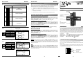
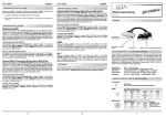
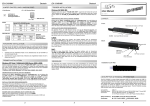
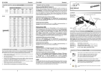
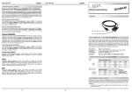
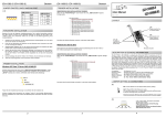
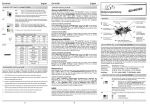
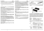
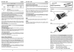
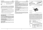
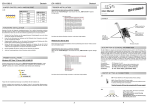
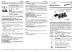
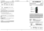
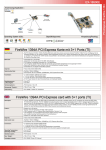
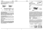
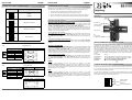
EX
EX--1311VIS
English
JUMPER SETTING & CONNECTORS
DIP-Switch
English
EX-1311VIS
HARDWARE INSTALLATION
Because there are large differences between PC’s, we can give you only a general installation
guide for the EX-1311VIS. Please refer your computers reference manual whenever in doubt.
Description
ON
M0
M1
M2
TERM
EX
EX--1311VIS
RS-232
(Default)
1.
Connect the USB cable (B-Plug) to the USB B-Port at the EX-1311VIS.
2.
After that connect the USB cable (A-Plug) to the USB A-Port at your PC.
3.
Now you can set the mode via the DIP switch. (see picture jumper setting and connectors)
4.
When you are ready you can start your PC and continue with the point Driver Installation.
Anleitung
Vers. 1.0 / 19.03.15
AUFBAU
TX/RX LED
für S1
ON
DRIVER INSTALLATION
M0
M1
M2
TERM
RS-485 2-wire mode
ON
M0
M1
Windows 2000/ XP/ Vista/ 7/ 8/ Server 200x
Windows will recognize a new „FT232R USB UART“ and open the hardware assistant. Please
choose manual installation and put the driver CD into your CD-ROM drive. Enter Path
"D:\USB_to_IO\FTDI\(32_64bit)Win7_8_XP_Vista_2008_2008R2_2003_2000”
into the box for the Path/Source and click at >next/continue<. Now Windows search for the
drivers in the specified directory. Follow the hardware assistant and finish the installation. If
Windows recognizes other new devices repeat the above described steps. Attention! Restart
Windows in any case after installing the drivers.
RS-485 4-wire mode
M2
TERM
Betriebs LED
USB B-Anschluss
(verschraubbar)
DIP-Schalter
CHECK THE INSTALLED DRIVER
ON
M0
M1
M2
TERM
Click at Start<>Run< then enter “compmgmt.msc“ and click at >OK<. In the windows that
open select >Device Manager<. Under ”Ports (COM and LPT)“ you should find one more
new „USB Serial Port (COM2)“. If you see this or similar entries the module is installed correctly.
RS-422 mode
S1:
9 Pin Stecker
Seriell RS-232/422/485
CHANGE PORT NUMBER (NOT WIN98 & ME)
If you like to change the port number for example COM3 to COM5, open the >Device Manager<
click at >COM3<, >Settings< and then >Advance<. There you can choose between COM3 up to
COM256.
RS-232 Pin Assignments
DB 9M
Windows 98/ 98SE/ ME
RS-232 Cable Wiring
DB9 (EX-1311VIS)
Serial 9 Pin D-SUB connector
RS-232 (Peripheral)
Windows will recognize a new “FT232R USB UART“ and open the hardware assistant. Please
choose manual installation and put the driver CD into your CD-Rom drive (as sample D:) . Now
enter the Path “D:\USB_to_IO\FTDI\Win98_ME” into the box for the Path/Source and click at
>next/continue<. Now Windows search for the drivers in the specified directory. Follow the
hardware assistant and finish the installation. If Windows recognizes other new devices repeat
the above described steps. Attention! Restart Windows in any case after installing the drivers.
Pin
Signal
Pin
Signal
1 DCD
1 DCD
1
CDC
6
DSR
2 RXD
2 RXD
2
RXD
7
RTS
3 TXD
3 TXD
3
TXD
8
CTS
4 DTR
4 DTR
CHECK THE INSTALLED DRIVER
4
DTR
9
RI
5 GND
5 GND
6 DSR
6 DSR
7 RTS
7 RTS
Click at Start<>Run< then enter “compmgmt.msc“ and click at >OK<. In the windows that
open select >Device Manager<. Under ”Ports (COM and LPT)“ you should find one more
new „USB Serial Port (COM2)“. If you see this or similar entries the module is installed correctly.
8 CTS
8 CTS
5
GND
BESCHREIBUNG & TECHNISCHE DATEN
Die EX-1311VIS ist ein Modul zur Umsetzung von USB 2.0 auf eine RS-232, 422 und 485
Schnittstelle mit FIFO 16C550 Port für den Anschluss von High Speed Seriellen RS232/422/485 Peripherie Geräten (z.B. Modem, Plotter usw.). Das USB Modul ist Hot Plug &
Play fähig. Für die Einstellungen der I/O Adressen und Interrupts sind keine Jumper und Einstellungen notwendig, da die Einstellungen automatisch vom System BIOS und bei der Installation des Betriebssystems vorgenommen werden. Die EX-1311VIS ist mit einem verschraubbarem USB B-Anschluss ausgerüstet und unterstützt 2.5KV Optical Isolation und 15KV Surge
Protection. Die verschiedenen Übertragungsarten können mittels DIP-Schalter eingestellt
werden.
Kompatibilität:
Betriebssysteme:
Anschlüsse:
Lieferumfang:
USB 2.0
WIN 9.x/ ME/ 2000/ XP/ Vista/ 7/ 8/ Server 200x/ Linux/ MAC
1x 9 Pin D-SUB Stecker, 1x USB B-Buchse (verschraubbar)
EX-1311VIS, Treiber CD, Anleitung, USB Kabel
Zertifikate:
CE / FCC / RoHS / WEEE
DE97424562
LINUX
RS-422/485 Pin Assignments
DB 9M
RS-422 Cable Wiring
DB9 (EX-1311VIS)
Serial 9 Pin D-SUB connector
Pin Signal
1 TXD-
Pin Signal
RS-422 (Peripheral)
TXD- (DATA-)
6
NC
2 TXD+
2 TXD+
2
TXD+ (DATA+)
7
NC
3 RXD+
3 RXD+
3
RXD+
8
NC
4 RXD-
4 RXD-
4
RXD-
9
NC
5 GND
5 GND
5
GND
RS-485 Cable Wiring:
There are drivers available for MAC. The drivers are located in the folder
“D:\USB_to_IO\FTDI\MAC OSX or Mac_OS_9_8“ on the driver CD. They are supported by
the most versions of MAC OS. Because each individual version of MAC OS is different, sadly
we cant provide a installation instruction. Please refer to the installation manual for standard I/O
ports from your MAC OS version !
3 RXD+
4 RXD-
4 RXD-
5 GND
5 GND
6
M2
4
3 RXD+
M1
3
2 DATA+
M0
2
2 DATA+
1
1 DATA-
Pin 4 (markiert mit TERM) hat die Funktion die Abschlusswiederstände für die RS-422/485
Modes ein oder auszuschalten. Eine Dokumentation der richtigen Einstellungsvarianten, finden
Sie auf Seite 2 und auf der Unterseite der EX-1311VIS.
ON
5
MAC
RS-485 (Peripheral)
1 DATA-
JUMPER EINSTELLUNG & ANSCHLÜSSE
Es gibt einen 4-Pin DIP-Schalter auf der Vorderseite der EX-1311VIS für den Port S1.
Pin 1, Pin 2 und Pin 3 (markiert mit M0, M1 und M2) hat die Funktion zwischen den drei Modes
RS-232, RS-422 und RS-485 umzuschalten.
1 TXD-
1
DB9 (EX-1311VIS)
There are drivers available for Linux. The drivers are located in the folder
“D:\USB_to_IO\FTDI\Linux x86_64“ on the driver CD. They are supported by the most versions of Linux. Because each individual distribution and kernel version of Linux is different,
sadly we cant provide a installation instruction. Please refer to the installation manual for standard I/O ports from your Linux version !
TERM
RS-232/422/485
Mode Schalter
1
Schalter für
Abschlusswiederstände
EX
EX--1311VIS
Deutsch
Beachten Sie bitte die folgenden Installationshinweise. Da es große Unterschiede zwischen PC‘s
gibt, können wir Ihnen nur eine generelle Anleitung zum Einbau der EX-1311VIS geben. Bei
Unklarheiten halten Sie sich bitte an die Bedienungsanleitung Ihres Computersystems.
Beschreibung
ON
M0
M1
RS-232
(Werkseinstellung)
M2
TERM
ON
M0
M1
M2
TERM
Deutsch
RS-485 2-Draht Mode
1.
Schließen Sie das mitgelieferte USB-Kabel an die USB B-Buchse des Moduls an.
2.
Verbinden Sie nun das andere Ende des USB-Kabel (A-Stecker) mit der A-Buchse an Ihrem
PC.
3.
Stellen Sie nun die DIP-Schalter auf den gewünschten Mode ein. (siehe Abbildung Jumper
Einstellungen und Anschlüsse)
4.
Jetzt können Sie Ihren PC starten und mit dem Punkt Treiber Installation fortfahren.
ON
Windows erkennt automatisch einen neuen „FT232R USB UART“. Legen Sie die Treiber CD in Ihr
CD-ROM Laufwerk ein (z.B. Laufwerk D:). Lassen Sie nicht automatisch nach dem Treiber suchen.
Sondern geben Sie folgenden Pfad manuell in das Feld “Quelldatei Pfad etc.“ ein. Die Treiber
liegen in dem Verzeichnis
"D:\USB_to_IO\FTDI\(32_64bit)Win7_8_XP_Vista_2008_2008R2_2003_2000”.
RS-485 4-Draht Mode
Manual
Vers. 1.0 / 19.03.15
LAYOUT
TX/RX LED
for S1
Power LED
TREIBER INSTALLATION
Windows 2000/ XP/ Vista/ 7/ 8/ Server 200x
M0
M1
M2
TERM
EX-1311VIS
HARDWARE INSTALLATION
JUMPER EINSTELLUNG & ANSCHLÜSSE
DIP-Schalter
EX
EX--1311VIS
USB B-Port
(screw lock)
DIP-Switch
ÜBERPRÜFEN DES INSTALLIERTEN TREIBERS
ON
M0
M1
Klicken Sie auf Start< >Ausführen< geben Sie “compmgmt.msc“ ein und klicken Sie auf
>OK<. Wählen Sie nun >GeräteManager<. Dort müssten Sie unter „Anschlüsse (COM und
LPT)“ neue Einträge „USB Serial Port (COM2)“ und unter „Universeller Serieller Bus
Controller“ den Eintrag „USB Serial Converter“ sehen. Wenn Sie diese oder ähnliche Einträge sehen, ist das USB Modul korrekt installiert.
RS-422 Mode
M2
TERM
S1:
9 Pin serial connector
RS-232/422/485
ÄNDERN DER COM ADRESSE (NICHT UNTER 98 & ME)
Öffnen Sie den Gerätemanager und klicken Sie z.B. auf >COM3< >Anschlusseinstellung<
und >Erweitert<. Sie können dann zwischen COM3 und COM256 wählen!
RS-232 Anschlussbelegung
Windows 98/ 98SE/ ME
Verdrahtung RS-232
DB 9M
DB9 (EX-1311VIS)
Seriell 9 Pin D-SUB Stecker
RS-232 (Endgerät)
Windows erkennt automatisch einen neuen „FT232R USB UART“. Legen Sie die Treiber CD in Ihr
CD-ROM Laufwerk ein (z.B. Laufwerk D:). Lassen Sie nicht automatisch nach dem Treiber suchen.
Sondern geben Sie folgenden Pfad manuell in das Feld “Quelldatei Pfad etc.“ ein. Die Treiber
liegen in dem Verzeichnis
"D:\USB_to_IO\FTDI\Win98_ME”.
Pin
Signal
Pin
Signal
1 DCD
1 DCD
1
DCD
6
DSR
2 RXD
2 RXD
2
RXD
7
RTS
3 TXD
3 TXD
3
TXD
8
CTS
4 DTR
4 DTR
ÜBERPRÜFEN DES INSTALLIERTEN TREIBER
4
DTR
9
RI
5 GND
5 GND
5
GND
6 DSR
6 DSR
7 RTS
7 RTS
8 CTS
8 CTS
Klicken Sie auf Start< >Ausführen< geben Sie “compmgmt.msc“ ein und klicken Sie auf
>OK<. Wählen Sie nun >GeräteManager<. Dort müssten Sie unter „Anschlüsse (COM und
LPT)“ neue Einträge „USB Serial Port (COM2)“ und unter „Universeller Serieller Bus
Controller“ den Eintrag „USB Serial Converter“ sehen. Wenn Sie diese oder ähnliche Einträge sehen, ist das USB Modul korrekt installiert.
LINUX
RS-422/485 Anschlussbelegung
Verdrahtung RS-422
DB 9M
DB9 (EX-1311VIS)
Seriell 9 Pin D-SUB Stecker
Pin Signal
1 TXD-
Pin Signal
RS-422 (Endgerät)
Die Linux Treiber befinden sich im Verzeichnis “D:\USB_to_IO\FTDI\Linux x86_64“ auf der
Treiber CD. Sie werden unter den meisten Linux Versionen unterstützt. Da sich die einzelnen
Distributionen und Kernelversionen sehr voneinander unterscheiden, können wir Ihnen leider
keine Installationsanweisung geben. Bitte halten Sie sich an die Installationsanweisung für USB
Ports Ihrer Linux Version.
1 TXD2 TXD+
MAC
3 RXD+
3 RXD+
3
RXD+
8
NC
4 RXD-
4 RXD-
4
RXD-
9
NC
5 GND
5 GND
5
GND
Die MAC Treiber befinden sich im Verzeichnis “D:\USB_to_IO\FTDI\MAC OSX oder
Mac_OS_9_8“ auf der Treiber CD. Sie werden unter den meisten MAC OS Versionen unterstützt. Da sich die einzelnen Versionen voneinander unterscheiden, können wir Ihnen leider
keine Installationsanweisung geben. Bitte halten Sie sich an die Installationsanweisung für USB
Ports Ihrer MAC OS Version.
Verdrahtung RS-485
DB9 (EX-1311VIS)
2
RS-485 (Endgerät)
1 DATA-
1 DATA-
2 DATA+
2 DATA+
3 RXD+
3 RXD+
4 RXD-
4 RXD-
5 GND
5 GND
3
DE97424562
JUMPER SETTING & CONNECTORS
There are one 4-pin DIP switches on the front side of the box for Port S1.
Pin 1, Pin 2 and Pin 3 (marked as M0, M1 and M2) shall used to set the RS-232, RS-422 or
RS-485 modes.
The Pin 4 (marked as TERM) are used to Enable (ON) or Disable (OFF) the termination resistors for RS-422/485 modes. A documentation of the correct setting options, see at page 5 and
on the underside of the EX-1311VIS.
M0
M1
M2
4
2 TXD+
NC
CE / FCC / RoHS / WEEE
3
NC
7
Certificates:
2
6
TXD+ (DATA+)
USB 2.0
WIN 9.x/ ME/ 2000/ XP/ Vista/ 7/ 8/ Server 200x/ Linux/ MAC
1x 9 Pin RS-232/422/485 connector, 1x USB B-Port (screw lock)
EX-1311VIS, Driver CD, Manual, USB Cable
1
TXD- (DATA-)
2
Compatibility:
Operating system:
Connectors:
Extent of delivery:
ON
1
DESCRIPTION & TECNICAL INFORMATION
The EX-1311VIS are plug & play high-speed USB 2.0 to Serial module for USB 2.0 ports with
up to 1 RS-232/422/485 9 pin connector. They provide one 9 pin serial port for serial devices
and one USB uplink port for PC. The USB to Serial module design utilizes the Chip-Set FTDI
with 16C550 UART. It is not possible to change the address or IRQ settings manually, they will
be obtained automatically by the operating system. The EX-1311VIS is additionally equipped
with screw lock USB 2.0 connectors and support 2.5KV Optical Isolation and 15KV Surge
Protection. With the dip-switch you can select RS-232, RS-422 or RS-485 mode.
TERM
RS-232/422/485
Mode Switch
4
Switch for
Statements Resistors