1
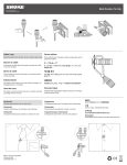
WA350 Carrying Case (WL51 only)
DUAL TIE CLIP
Models WL50/WL51 and
MC50/MC51 User Guide
MAGNET MOUNT
SWIVELING LAPEL
CLIP
WARNING:
THE MAGNET MOUNT SHOULD NOT
BE USED BY PERSONS FITTED
WITH AN IMPLANTED MEDICAL
DEVICE, SUCH AS A PACEMAKER
OR DEFIBRILLATOR.
2005, Shure Incorporated
27F3114 (Rev. 5) Printed in U.S.A.
GENERAL
Shure models WL50/MC50 (omni) and WL51/MC51 (unidirectional) are subminiature, electret condenser lavalier microphones. They provide uncompromised sound quality and high
reliability with minimal visibility in sound reinforcement applications such as television broadcasting and stage performances. Despite its small size, the microphone’s condenser element provides full, clear and natural reproduction of speech. Each microphone is supplied
with two foam windscreens to minimize wind noise. The supplied mounting accessories consist of a lapel clip, a tie clip, a pin mount, and a magnet mount, giving the user a wide variety
of options for placement.
MODEL VARIATIONS
WL50 (omni)/WL51 (uni): Intended for wireless use. Connects to Shure wireless
bodypack transmitters via a TA4F connector.
WL50X (omni)/WL51X (uni): Supplied with a 3 m (10 ft.) stripped and tinned cable for
wiring to an alternate connector.
WL50–LO: A lower sensitivity variation of the WL50, supplied with a TA4F connector.
(omnidirectional)
WL50X–LO: A lower sensitivity version of the WL50, supplied with stripped and tinned
leads. (omnidirectional)
MC50 (omni)/MC51 (uni): Intended for hardwired applications. WL50 or WL51
microphone supplied with an in-line preamplifier with a three-pin male XLR audio
connector.
FEATURES
S Extended frequency response with user changeable equalization caps for response
shaping (omni only)
S Low visibility with a variety of options for mounting
S WL50—(omnidirectional) offered in black, beige, and white with matching accessories
S WL51—(unidirectional) offered in black and white with matching accessories
S Low handling noise
S Legendary Shure quality, ruggedness, and reliability
WINDSCREENS
Two acoustic foam windscreens are supplied to help reduce undesirable wind noise.
PIN MOUNT
SUPPLIED MOUNTING ACCESSORIES
MOUNTING THE MICROPHONE
The WL50/WL51 and MC50/MC51 microphones come with the following
mounting accessories:
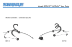
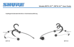
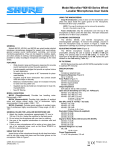
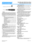
Swiveling Lapel Clip. Features a spring-loaded clasp that attaches easily to a necktie, lapel,
blouse or shirt, connected to a rotatable mounting clip. To mount, snap the microphone cable
into the clip near the neck of the microphone, then attach the clasp to an article of clothing.
Rotate the mounting clip to place the microphone at desired angle.
Dual Tie Clip. Features a spring-loaded clasp that attaches easily to a necktie or suit coat
lapel, and a clip that holds one or two microphones. To mount, snap the microphone cable(s)
into the clip near the neck of the microphone, then attach the clasp to an article of clothing.
Pin Mount. Features a translucent mounting clip with two straight pins that easily secure to
an article of clothing. To mount, slide the straight pins into clothing, then snap the microphone
cable into the mounting clip near the neck of the microphone.
Magnet Mount. Features a backplate that is worn under clothing and attaches to a magnetic
mount capable of holding one or two microphones. To mount, place the magnetic backplate
“necklace” around neck and under clothing, then align the magnet mount to the backplate and
secure it to clothing. Snap microphone cable(s) into the clip near the neck of the microphone,
and adjust the magnet mount to hold microphone at the desired angle.
WARNING: The magnet mount should not be used by persons
fitted with an implanted medical device, such as a pacemaker or
defibrillator.
FURNISHED ACCESSORIES
Foam Windscreen (2 pcs.): Black, beige or white
* Mild Boost Equalization Cap (2 pcs.): Black, beige or white
High Boost Equalization Cap (2 pcs.): Black, beige or white
Swiveling Lapel Clip: Black, beige or white
Dual Tie Clip: Black, beige or white
Preamplifier with hardware (MC50/MC51 only) . . . . . . . . . . . . . . . . . . . . . . . . . . . . . . . . . . . . RPM626
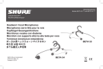
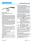
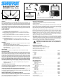
EQUALIZATION CAPS
The WL50 and the MC50 omnidirectional models are each supplied with two types of equalization caps for high frequency response shaping. The caps effect the response range between 5,000 and 20,000 Hz (see Figure 4), and can be distinguished by the color of their
mesh screens. The mild boost equalization cap has a very fine mesh, silver color screen,
and attenuates the natural high frequency peak of the microphone. The high boost equalization cap has an open mesh gold color screen and does not attenuate the high frequency peak.
The WL51 and MC51 unidirectional models are supplied with the high boost equalization cap only. The WL51 and MC51 models should never be used with the mild boost
equalization cap because the unidirectional pick-up pattern will be severely altered.
This is due to partial blocking of the front opening, and they will not perform correctly.
Pin Mount . . . . . . . . . . . . . . . . . . . . . . . . . . . . . . . . . . . . . . . . . . . . . . . . . . . . . . . . . . . . . . . . . . . 95A2162
NOTE: For best sound quality, replace the equalization caps if they become
clogged with make-up.
High Boost Equalization Caps
Black (5 pcs.) . . . . . . . . . . . . . . . . . . . . . . . . . . . . . . . . . . . . . . . . . . . . . . . . . . . . . . . . . . RPM208
Beige (5 pcs.) (omni only) . . . . . . . . . . . . . . . . . . . . . . . . . . . . . . . . . . . . . . . . . . . . . . . . RPM212
White (5 pcs.) . . . . . . . . . . . . . . . . . . . . . . . . . . . . . . . . . . . . . . . . . . . . . . . . . . . . . . . . . . RPM216
USING THE MC50/MC51 WITH A MIXER
The preamplifier supplied with both the MC50 and MC51 requires phantom power ranging
from 11 to 52 Vdc. Connect the preamplifier to a mixer input with a minimum load impedance
of 800 Ω to maximize operating headroom.
Mild Boost Equalization Caps (omni only)
* Black (5 pcs.) . . . . . . . . . . . . . . . . . . . . . . . . . . . . . . . . . . . . . . . . . . . . . . . . . . . . . . . . . RPM220
Beige (5 pcs.) . . . . . . . . . . . . . . . . . . . . . . . . . . . . . . . . . . . . . . . . . . . . . . . . . . . . . . . . . . RPM214
* White (5 pcs.) . . . . . . . . . . . . . . . . . . . . . . . . . . . . . . . . . . . . . . . . . . . . . . . . . . . . . . . . . RPM218
USING THE WL50/WL51 WITH OTHER BODYPACK TRANSMITTERS
If connecting the WL50/WL51 to anything OTHER than a Shure wireless bodypack, make
sure the device provides a regulated +5 Vdc (130 A minimum) to the red conductor. Refer
to the wiring diagrams in Figures 6 and 7.
WIRING THE WL50X/WL51X TO AN ALTERNATE CONNECTOR
Model WL50X/WL51X is supplied with a stripped and tinned cable for wiring to a variety of
connectors. Refer to the WL50X/WL51X wiring diagram in Figure 6. For additional information on wiring the WL50X/WL51X to an alternate connector, contact Shure’s Applications Department at (847) 600–8440 or 1–800–516–2525.
Magnet Mount
Black . . . . . . . . . . . . . . . . . . . . . . . . . . . . . . . . . . . . . . . . . . . . . . . . . . . . . . . . . . . . . . . . . 90A4694
Beige . . . . . . . . . . . . . . . . . . . . . . . . . . . . . . . . . . . . . . . . . . . . . . . . . . . . . . . . . . . . . . . . . 90B4694
White . . . . . . . . . . . . . . . . . . . . . . . . . . . . . . . . . . . . . . . . . . . . . . . . . . . . . . . . . . . . . . . . . 90C4694
OPTIONAL ACCESSORIES
Phantom Power Supply . . . . . . . . . . . . . . . . . . . . . . . . . . . . . . . . . . . . . . . . . . . . . . . . . . . . . . . . . . . PS1A
Battery-Operated Preamplifier . . . . . . . . . . . . . . . . . . . . . . . . . . . . . . . . . . . . . . . . . . . . . . . . . . . MX1BP
REPLACEMENT PARTS
Foam Windscreen
Black (5 pcs.) . . . . . . . . . . . . . . . . . . . . . . . . . . . . . . . . . . . . . . . . . . . . . . . . . . . . . . . . . . RPM304
Beige (5 pcs.) . . . . . . . . . . . . . . . . . . . . . . . . . . . . . . . . . . . . . . . . . . . . . . . . . . . . . . . . . . RPM306
White (5 pcs.) . . . . . . . . . . . . . . . . . . . . . . . . . . . . . . . . . . . . . . . . . . . . . . . . . . . . . . . . . . RPM308
2 Swivel Lapel Clips and 2 Dual Tie Clips
Black . . . . . . . . . . . . . . . . . . . . . . . . . . . . . . . . . . . . . . . . . . . . . . . . . . . . . . . . . . . . . . . . . RPM500
Beige . . . . . . . . . . . . . . . . . . . . . . . . . . . . . . . . . . . . . . . . . . . . . . . . . . . . . . . . . . . . . . . . . RPM502
White . . . . . . . . . . . . . . . . . . . . . . . . . . . . . . . . . . . . . . . . . . . . . . . . . . . . . . . . . . . . . . . . . RPM504
Mini 4–pin (TA4F type) Connector . . . . . . . . . . . . . . . . . . . . . . . . . . . . . . . . . . . . . . . . . . . . . . . . . WA331
Carry Case (WL51 only) . . . . . . . . . . . . . . . . . . . . . . . . . . . . . . . . . . . . . . . . . . . . . . . . . . . . . . . . . WA350
* Not used with WL51, MC51 models
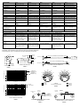
SPECIFICATIONS
WL50{
WL50–LO{
MC50}
WL51{
MC51}
Type
Condenser (electret bias)
Condenser (electret bias)
Condenser (electret bias)
Condenser (electret bias)
Condenser (electret bias)
Polar Pattern
Omnidirectional
Omnidirectional
Omnidirectional
Cardioid
Cardioid
Output Impedance
N/A
N/A
136 actual (rated at 150 )
N/A
136 actual (rated at 150 )
Recommended Min. Input
Impedance
20 k
20 k
N/A
20 k
N/A
Output Level
–45.0 dBV/Pa
(1 Pa=94 dB SPL)
–54.0 dBV/Pa
(1 Pa=94 dB SPL)
–41.0 dBV/Pa
(1 Pa=94 dB SPL)
–50.0 dBV/Pa
(1 Pa=94 dB SPL)
–46.0 dBV/Pa
(1 Pa=94 dB SPL)
Maximum SPL
133 dB at 1% THD/
20k load
142 dB at 1% THD/
20k load
138 dB at 1% THD/
1 k ohm load
138 dB at 1% THD/
20k load
143 dB at 1% THD/
1 k ohm load
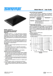
Frequency Response
20 to 20,000 Hz (see Figure 5)
Dynamic Range
103.0 dB
103.0 dB
108.0 dB
103.0 dB
108.0 dB
Output Noise
(equivalent SPL, A-weighted)
30 dB typical; 33 dB maximum
39 dB typical; 42 dB maximum
30 dB typical; 33 dB maximum
35 dB typical; 38 dB maximum
35 dB typical; 38 dB maximum
Signal-to-Noise
Ratio
64 dB at 94 dB SPL
55 dB at 94 dB SPL
64 dB at 94 dB SPL
59 dB at 94 dB SPL
59 dB at 94 dB SPL
Power Requirements
+5 Vdc on pin 2, return on pin 1
(ground).
+5 Vdc on pin 2, return on pin 1
(ground).
11 to 52 Vdc (positive on pins 2
and 3, return on pin 1).
+5 Vdc on pin 2, return on pin 1
(ground).
11 to 52 Vdc (positive on pins 2
and 3, return on pin 1).
Current Drain
60–130 A
60–130 A
4.6 mA
60–130 A
4.6 mA
Polarity—Positive pressure on
the diaphragm produces a
positive voltage at:
Pin 3 relative to pin 1 at the output connector of the microphone.
pin 2 relative to pin 3 of the output
connector of preamplifier.
pin 3 relative to pin 1 at the
output connector of the
microphone.
pin 2 relative to pin 3 of the output
connector of preamplifier.
Overvoltage Protection
N/A
±75.0 Vdc maximum from pins
2 and 3 to pin 1.
N/A
±75.0 Vdc maximum from pins
2 and 3 to pin 1.
Cap and Overmold Material
Polypropylene
Environmental Conditions
Operating Temperatures: –18_ to 57_ C (0_ to 135_ F)
Packaged Weight
188 g (6.63 oz.)
188 g (6.63 oz.)
305 g (10.76 oz.)
188 g (6.63 oz.)
305 g (10.76 oz.)
Cable and
Connector
1.5 m (5 ft.), small-diameter,
shielded, with miniature female
4-pin connector (TA4F type).
WL50X: 3 m (10 ft.)
small-diameter, shielded, with
stripped and tinned leads.
1.5 m (5 ft.), small-diameter,
shielded, with miniature female
4-pin connector (TA4F type).
WL50X–LO: 3 m (10 ft.)
small-diameter, shielded, with
stripped and tinned leads.
1.5 m (5 ft.), small-diameter,
shielded, with miniature female
4-pin connector (TA4F type).
1.5 m (5 ft.), small-diameter,
shielded, with miniature female
4-pin connector (TA4F type).
WL50X: 3 m (10 ft.)
small-diameter, shielded, with
stripped and tinned leads.
1.5 m (5 ft.), small-diameter,
shielded, with miniature female
4-pin connector (TA4F type).
Microphone and Preamp
Dimensions
See Figures 2 and 3
Net Weight
WL50: 21 g (0.7 oz.) with cable
and connector.
WL50X: 28 g (1.0 oz.) with 3 m
(10 ft.) stripped and tinned
cable.
WL50–LO: 21 g (0.7 oz.) with
cable and connector.
WL50X–LO: 28 g (1.0 oz.) with
3 m (10 ft.) stripped and tinned
cable.
121 g (4.3 oz.) with cable,
connector, and preamplifier.
WL51 21 g (0.7 oz.) with cable
and connector. WL51X: 28 g
(1.0 oz.) with 3 m (10 ft.)
stripped and tinned cable.
121 g (4.3 oz.) with cable,
connector, and preamplifier.
N/A
Storage Temperatures: –29_ to 74_ C (–20_ to 165_ F)
{ Measured
} Measured
Certification: Eligible to bear CE marking. Conforms to European EMC directive
89/336/EEC. Meets applicable test and performance criteria in European EMC standard EN
55103 (1996) parts 1 and 2, for residential (E1) and light industrial (E2) environments.
1.0 uf
1.52 m (5 ft.) for WL50/MC50 and WL51/MC51 Series
5.8 mm (.23 in.)
4
2
19 mm DIA.
(.75 in.)
100 k
20 k
with test circuit (see Figure 1).
with RPM626 Preamplifier.
14 mm
(.55 in.)
20 mm DIA.
(.79 in.)
3
1
Humidity: 0 to 95%
5 Vdc
3.04 m (10 ft.) for WL50X/WL51X Series
99 mm
(3.89 in.)
5.8 mm (.23 in.)
PREAMPLIFIER DIMENSIONS
STANDARD TEST CIRCUIT
MICROPHONE AND CABLE DIMENSIONS
FIGURE 2
FIGURE 3
FIGURE 1
RELATIVE RESPONSE IN dB
Mild Boost
Equalization Cap
180 o
150 o
High Boost
Equalization Cap
120 o
120 o
90 o
90 o
90 o
–20 dB
–15 dB
60 o
60 o
–10 dB
–20 dB
–15 dB
–10 dB
60 o
–5 dB
30 o
Omnidirectional
30 o
30 o
30 o
0
0
2500 Hz
6400 Hz
10000 Hz
CARDIOID
TYPICAL POLAR PATTERN
180o Off Axis
RELATIVE RESPONSE IN dB
60 o
–5 dB
250 Hz
500 Hz
1000 Hz
On Axis
150 o
120 o
120 o
90 o
180 o
150 o
150 o
FIGURE 5
IMPEDANCE
CONVERTER
CONDENSER CARTRIDGE
G
D
+
S
CONDENSER
CARTRIDGE
RED
BLK
SHIELD
+5 Vdc
AUDIO OUT
GROUND
IMPEDANCE
CONVERTER
G
D
S
RED
+5 Vdc
BLK
Audio Out
SHIELD
1 3
4 2
Cardioid
TYPICAL FREQUENCY RESPONSE
FIGURE 4
WL50X SERIES MICROPHONE WIRING DIAGRAM
(UNTERMINATED)
FIGURE 6
WL50/MC50 and WL51/MC51 SERIES MICROPHONE
WIRING DIAGRAM WITH TA4F CONNECTOR
FIGURE 7