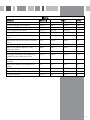
Electrical Information
Mains electrical voltage: 230 – 240Vac, 50Hz
Total rated power consumption:
290W
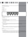
Troubleshooting
If your extractor is not working:
1. Check that the mains supply has not been switched off.
2. Check that the fuse in the spur has not blown.
7