1
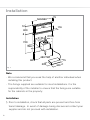
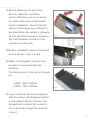
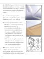
edd61 & edd91
Extractors
Installation, Use and Maintenance
Customer Care Department • The
Group Ltd. • Harby Road • Langar • Nottinghamshire • NG13 9HY
T : 01949 862 012 F : 01949 862 003 E : [email protected] W : www.cda.eu
www.cda.eu
Important
The CDA Group Ltd cannot be held responsible for injuries or losses
caused by incorrect use or installation of this product. Please note
that CDA reserve the right to invalidate the guarantee supplied with
this product following incorrect installation or misuse of the appliance
or use in a commercial environment.
This appliance is not designed to be used by people (including
children) with reduced physical, sensorial or mental capacity, or
who lack experience or knowledge about it, unless they have had
supervision or instructions on how to use the appliance by someone
who is responsible for their safety.
Under no circumstances should any external covers be removed for
servicing or maintenance except by suitably qualified personnel.
Appliance information:
Please enter the details on the appliance rating plate below for
reference, to assist CDA Customer Care in the event of a fault with
your appliance and to register your appliance for guarantee purposes.
Appliance Model
Serial Number
2
CE Declarations of Conformity:
This appliance has been manufactured to the strictest standards and
complies with all applicable legislation, including Gas safety, Electrical
safety (LVD) and Electromagnetic interference compatibility (EMC).
IMPORTANT INFORMATION FOR CORRECT DISPOSAL OF THE
PRODUCT IN ACCORDANCE WITH EC DIRECTIVE 2002/96/EC.
At the end of its working life, the product must be taken to a special
local authority waste collection centre or to a dealer providing
appliance recycling services.
Disposing of a household appliance separately avoids possible
negative consequences for the environment and health. It also
enables the constituent materials to be recovered, saving both energy
and resources. As a reminder of the need to dispose of household
appliances separately, the product is marked with a crossed-out
wheeled dustbin.
Please note:
• Under no circumstances should the extractor be connected to any
gas ventilation system, flue system or hot air ducting system.
• Do not vent the extractor into an attic or loft space.
• Only house the extractor in rooms with adequate ventilation.
Remember that the extractor is powerful and whatever air is
extracted needs to be replaced.
• Do not tile the extractor in. It should be removable for service or
maintenance.
• You must be able to isolate the extractor from the mains electrical
supply after installation.
• This extractor has been designed to be used in a room with a
volume of less than 90 m3.
3
• Steam cleaners must not be used when cleaning this appliance.
• The performance of your extractor will vary depending on a number
of factors. These include: type of extraction, length of ducting, room
volume, ventilation available and cleanliness of the filters.
4
Using Your Extractor
For best performance, you should switch on the extractor 15 minutes
before starting to cook and leave it to run for approximately 15
minutes after the end of cooking.
A
B
C
D
E
Fig. 1
Control Panel
A - Off key
B - On / “+” key
C - Speed selection display (4 LED’s)
D - “-” key
E - Timer key
To switch on the extractor or to increase the speed at any time
• While the appliance is switched off, touch the “On/+” key
once
to raise the extraction panel to its full height. The moving panel will
raise to its operating position and the appliance will start to extract
at its slowest speed once it reaches 180mm above its rest position.
• To increase the speed, wait until the extractor has reached its full
height and is running at the first speed, then touch the “On/+” key
several times, until the desired speed is reached.
• The number of LED’s lit on the speed selection display
corresponds to the speed setting number (e.g. 2 LED’s lit for the
second speed).
5
To decrease the speed at any time
• Touch the “-” key
a few times, until the required speed is
reached.
To switch off the extractor
• Touch the “Off” key : The moving panel will descend to its rest
position and the appliance will continue extracting until its height
drops below approx. 180mm, at which point the extraction will stop.
Timed operation
once
• While the extractor is operating, touching the “Timer” key
will set it to run for a further ten minutes then automatically shut
down. This feature is most useful when you finish cooking and
need to leave the kitchen unattended.
Other features
• After approx. 30 hours of operation the speed selelction display on
the control panel will flash to signify that the grease filters are due
for cleaning. After they are cleaned and replaced (page 8) press
once to reset the grease filter alarm timer.
the “Timer” key
• After the appliance has been running for 4 hours since the last
key touch, it will automatically shut down. This is not a fault and is
a feature to save power in the event that the appliance has been
forgotten.
• When the front panel is removed for cleaning, all the movement and
extraction functions are locked for safety.
• If anything obstructs the closure of the moving panel it will
automatically stop and return to its fully open position.
6
Energy saving feature
This extractor is fitted with an energy saving feature that automatically
reduces the motor speed if it is left on the highest setting. When the
motor speed is set to the fourth level, it will automatically switch to
level three after six minutes of operation.
Care and Maintenance
IMPORTANT: DO NOT PERFORM MAINTENANCE OR CLEANING
OF THE EXTRACTOR WITHOUT FIRST SWITCHING OFF THE
ELECTRICITY SUPPLY.
Cleaning
You should use a non-abrasive cleaner. Any abrasive cleaner
(including Cif) will scratch the surface and could erase the control
panel markings.
You can clean your extractor effectively by simply using a dilute
solution of water and mild detergent and drying to a shine with a
clean cloth, for example the CDA E-Cloth.
Cleaning the grease filters
The grease filters should be kept clean to minimise the risk of fire.
At least once a month you should remove and clean the grease
filters with hot soapy water. You can also wash the grease filters in
a dishwasher, ensuring that you place them in an upright position to
prevent damage from other items in the dishwasher. After rinsing and
drying, replace the filters.
7
To remove and replace the grease
filters
• Touch the “On/+” key
so the
moving panel raises to its full extent,
Pull
then isolate the power supply so it
stays raised.
• By pulling the two top corners of the
Fig. 2
front panel (Fig. 2) at the same time,
it will be released and pivot toward
you.
• The grease filters can then be pulled forward and out.
• Replacement is a reversal of the removal procedure.
Please note:
Cleaning the grease filters in the dishwasher may lead to
discolouration. This is normal and does not constitute a fault with the
appliance.
Changing the charcoal filters (re-circulating only)
To ensure best performance of your extractor, you should replace the
charcoal filters every four to six months, depending on use.
To replace the charcoal filters
• Remove the grease filters as described opposite.
• The charcoal filters can then be lifted out and the replacements
placed in position.
• Replace the grease filters as opposite.
8
Mounting your Extractor
When the extractor is to be installed behind an electric or gas hob,
the minimum distance between the hob and extractor must exceed
50mm. In the case of a gas hob, the minimum distance from any
burner to the back of the hob must also be 65mm.
If the instructions provided with your gas hob state that the required
distance between the hob and extractor must be greater than
specified above, then that is the distance that should be observed;
this is a legal requirement and may lead to your hob being
disconnected from the gas supply and the installation being reported
to RIDDOR.
IN THE ABSENCE OF ANY INSTRUCTIONS SUPPLIED WITH THE
GAS HOB, THE MINIMUM DISTANCE BETWEEN THE HOB AND
EXTRACTOR MUST BE AT LEAST 50mm.
The width of any hob must not be greater than the width of the
extractor installed with it.
9
Troubleshooting
You observe that
The hood does not work.
The output is low.
Possible Causes
What should you do?
There ia a power outage.
Check the power supply.
The 9 pin connector is faulty or
misconnected.
Check the orientation and
security of the 9 pin connector.
The internal breaker has tripped.
Press the red reset key on the
electronic box.
The setting is insufficient for the
fumes present.
Try a more powerful setting.
Inadequate ventilation into the
kitchen.
Ensure there is adequate facility
for air intake to the kitchen.
The charcoal filter (if fitted) is
blocked.
Replace the charcoal filter.
The exit ducting is obstructed.
Remove any obstructions from
the ducting.
The exit flaps on the motor
housing are restricted.
Ensure the flaps rotate freely.
There ia a power outage.
Check the power supply.
The circuit breaker or fuse has
tripped.
Check the circuit breaker or fuse.
The hood stops in mid operation.
In the event of a fault with the extractor, please contact CDA Customer
Care for assistance.
Contact CDA Customer Care
A: Customer Care Department, The CDA Group Ltd, Harby Road,
Langar, Nottinghamshire, NG13 9HY
T: 01949 862 012
F: 01949 862 003
E: [email protected]
10
Ducting and Ventilation
• For best performance and lowest noise output, we recommend
the use of 150mm ducting. Use of any smaller ducting will reduce
performance and increase noise.
• The length of ducting should not exceed 5 metres in total.
• Limit the use of elbows in the ducting to a minimum: Bear in mind
that each elbow imposes a similar restriction to flow to a 1 metre
length of straight ducting.
• Avoid abrupt changes in direction for the ducting.
• Ensure that the ducting used satisfies all local and national
standards applicable to the installation.
11
Installation
75
560/860
12
880
300
8
116
Ø150
720
346
96
480/780
200
Fig. 3
75
440
Note
• We recommend that you seek the help of another individual when installing this product.
• The fixings supplied are suitable for most installations. It is the responsibility of the installer to ensure that the fixings are suitable
for the cabinets in the property.
Installation
1) Prior to installation, check that all parts are present and free from
transit damage. In event of damage being discovered contact your
supplier and do not proceed with installation.
12
2) Before making a cut-out in the
kitchen cabinets or worktop,
ensure that there are no structural
(or other) obstructions that would
hinder installation. Ensure that the
cabinet dimensions are sufficient to
accommodate the extractor, allowing
for the specified clearance between
the final installed positions of the
extractor and the hob.
Fig. 4
3) Before installation remove the transit
pieces shown in fig. 4, 5, & 6.
4) Make a rectangular cut-out in the
worktop to accommodate the
extractor.
The dimensions of the cut-out should
be:
edd61 - 490 x 100mm
edd91 - 790 x 100mm
Fig. 5
Fig. 6
5) If your extractor has been supplied
with the motor unit already mounted
on the main body, this needs to be
dismantled to enable the extractor
to be inserted through the worktop
cut-out.
13
6) Locate the support frame (trim piece);
apply a narrow bead of silicone sealant
to the underside of this (Fig. 7). Position
this around the cut-out in the worktop
(Fig. 8).
7) Lower the main body of the
downdraft extractor through the support
frame and into its fitted position.
8) Fix the downdraft extractor inside
the cabinet using the special fixing
brackets supplied (Fig. 9).
i) The brackets should first be
attached to the extractor body
in such a way that they leave a
gap of approx. 2mm between
the brackets and the base of the
cabinet.
ii) The screws fixing the brackets to
the cabinet base are then used to
pull the downdraft extractor firmly
into its final installed position.
Note: Ensure that the downdraft
extractor unit is vertical and
perpendicular to the worktop before
fitting the brackets to the cabinet base.
14
Fig. 7
Fig. 8
Fig. 9
9) R
efit the motor unit to the main body
of the downdraft extractor. This may
be positioned with the outlet facing
vertically upward or downward.
10) Connect suitable ducting to the
extractor outlet. See page 11 for
ducting requirement details.
11) Position the metal box containing
the electronic components in the
cabinet, no closer than 65mm to any
gas operated hob and no closer than
65mm to the extraction outlet.
We recommend installing the box
containing the electronics at least
10cm above floor level and at a
suitable distance from all sources of
heat (e.g. oven sides, hob base).
12) Plug the 9 pin electrical connector
from the electronic box into the
downdraft body, being careful to
orientate it correctly (Fig. 10).
13) Lift the downdraft moving panel and
remove the door block (Figs. 11, 12 &
13).
Fig. 10
Fig. 11
Fig. 12
Fig. 13
15
14) Open the filter cover (Figs. 14 & 15)
then remove the grease filter
package identified in Fig. 15.
Pull
15) P
osition the grease filters as shown
in Fig. 16.
Downdraft Calibration
After installation it is necessary to
calibrate the downdraft mechanism.
• Connect the power supply to the
extractor.
• Touch the “On/+” key to start the
moving panel rising.
• After the panel has risen by approx.
180mm touch the “Off” key to stop it
from rising any further.
• Touch the “Timer” key once.
• After 2 seconds touch the “Off” key
again.
• The LED’s on the control panel will
flash to show that the downdraft
extractor is carrying out its calibration
procedure and the panel will raise/
lower.
• When the calibration procedure is
complete the LED’s will stop flashing
and the appliance may be operated
normally.
16
Fig. 14
Fig. 15
Fig. 16
Mains Electricity Connection
Warning! This appliance must be earthed.
Green and Yellow to Earth
A
13 Amp
Brown to Liv e
B
13 Amp fuse
Cord Clamp
Fig. 17
Blue to Neutra l
The mains lead of this appliance has been fitted with a BS 1363A
3Amp fused plug. To change a fuse in this type of plug, follow the
steps below:
1. Remove the fuse cover and fuse.
2. Fit replacement 3A fuse, ASTA approved to BS 1362 type, into the
fuse cover.
3. Replace fuse cover.
Important: Do not use the appliance without the fuse cover in
position.
How to connect an alternative plug
If the fitted plug is not suitable for your socket outlet, then it should
be cut off and disposed of safely to avoid possible shock hazard. A
suitable alternative plug of at least 3 Amp rating to BS 1363 should be
used.
17
As the colours of the wires in the mains lead of this appliance may not
correspond with the coloured markings identifying the terminals in
your plug, proceed as follows:• The wire which is coloured GREEN and YELLOW must be connected
to the terminal which is marked with letter (E) or by the Earth symbol
or coloured GREEN and YELLOW.
• The wire which is coloured BLUE must be connected to the terminal
which is marked with the letter (N) or coloured BLACK.
• The wire which is coloured BROWN must be connected to the
terminal which is marked with the letter (L) or coloured RED.
If in doubt regarding the electrical connection of this appliance,
consult a qualified electrician. Do not shorten the supply cable, the
appliance may require removing for servicing.
N.B. Ensure that the plug socket is situated in an easily accessible
place after installation.
Electrical Information
Mains electrical voltage: 240Vac.
Total rated power consumption: 200W
18
Fiche
Attribute
Model Identification
Annual Energy Consumption
Time increase factor
Fluid Dynamic Efficiency
Energy Efficiency Index
Measured airflow at Best Efficiency
Point
Measured Pressure at Best Efficiency
Point
Maximum airflow
Measured electric power at Best
Efficiency Point
Nominal lighting power
Average illumination of the lighting
system on the cooking surface
Measured power consumption in
standby
Measured power consumption off
mode
Sound power level
Grease Filter Efficiency
Lamp efficiency
Symbol
Value
edd91
49.6
0.9
30.2 (A)
50.4
344.0
Units
AECHood
f
FDEHood
EEIHood
QBEP
edd61
54.0
1.0
26.5 (B)
55.8
317.0
PBEP
446.0
477.0
Pa
QMAX
WBEP
636.0
148.0
757.0
151.0
m3/h
W
WL
EMiddle
0.0
0.0
0.0
0.0
W
Lux
PS
0.5
0.5
W
PO
0.0
0.0
W
LWA
GFEHood
LEHood
69.0
61.1 (E)
0.0
61.0
63.0 (E)
0.0
dBA
%
%
kWh
m3/h
E & O E. All instructions, dimensions and illustrations are provided for guidance only. CDA reserve the
right to change specifications without prior notice.
19
Please contact our Customer Care Department for Service on the details below
Customer Care Department
The
Group Ltd. • Harby Road • Langar • Nottinghamshire • NG13 9HY
T : 01949 862 012 F : 01949 862 003 E : [email protected]
Customer Care Department • The
Group Ltd. • Harby Road • Langar • Nottinghamshire • NG13 9HY
T : 01949 862 012 F : 01949 862 003 E : [email protected] W : www.cda.eu
Copyright © CDA 2015
www.cda.eu