1
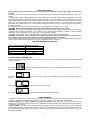
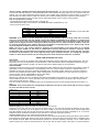
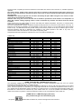
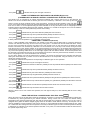
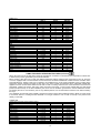
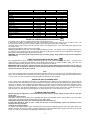
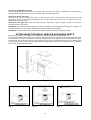
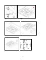
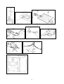
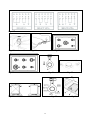
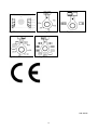
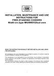
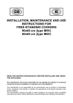
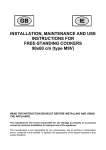
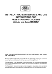
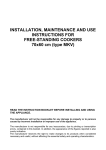
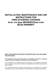
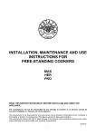
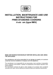
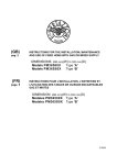
INSTALLATION, MAINTENANCE AND USE
INSTRUCTIONS FOR
FREE-STANDING COOKERS
90x60 cm (type M92/M92V)Dual oven
READ THE INSTRUCTION BOOKLET BEFORE INSTALLING AND USING
THE APPLIANCE.
The manufacturer will not be responsible for any damage to property or to persons
caused by incorrect installation or improper use of the appliance.
The manufacturer is not responsible for any inaccuracies, due to printing or transcription
errors, contained in this booklet. In addition, the appearance of the figures reported is also
purely indicative.
The manufacturer reserves the right to make changes to its products when considered
necessary and useful, without affecting the essential safety and operating characteristics.
CONTENTS:
INSTALLER TECHNICAL MANUAL ............................................................................................................... pg. 2
Installing the cooker - Installation information ................................................................................................. pg. 2
Ventilation and aeration of rooms.................................................................................................................... pg. 3
Height adjustable legs .................................................................................................................................... pg. 3
Backguard installation instruct ........................................................................................................................ pg. 3
Gas connection ............................................................................................................................................... pg. 3
Adaptation to different types of Gas and burner adjustments.......................................................................... pg. 3-4
Electric connection .......................................................................................................................................... pg. 4-5
APPLIANCE MAINTENANCE - Replacing parts ............................................................................................. pg. 5
USE AND MAINTENANCE MANUAL ............................................................................................................. pg. 6
Description of control panel and control types................................................................................................. pg. 6
Using burners .................................................................................................................................................. pg. 6-7
Using the gas oven ........................................................................................................................................ pg. 7-8
Using the electric thermostat ........................................................................................................................... pg. 8
Using the 2+0 switch.......................................................................................... .............................................. pg. 8
Using the thermostat with switch in series....................................................................................................... pg. 8
Using the 9+0 switch ....................................................................................................................................... pg. 9
Using the natural conventional electric oven .................................................................................................. pg. 9-10
Using the ventilated electric oven .................................................................................................................... pg. 10
Using the electric grill - ventilated electric grill ................................................................................................. pg. 11
Using the self cleaning oven .......................................................................................................................... pg. 11
Cleaning the appliance .................................................................................................................................... pg. 11
After-sales technical service and spare parts .................................................................................................. pg. 12
THIS APPLIANCE HAS BEEN DESIGNED FOR NON-PROFESSIONAL DOMESTIC USE.
INSTALLER TECHNICAL MANUAL
This appliance is marked according to the European directive 2002/95/EC
This appliance is marked according to the European directive 2002/96/EC on Waste
Electrical and Electronic Equipment (WEEE).
This guideline is the frame of a European-wide validity of return and recycling on
Waste Electrical and Electronic Equipment.
INSTALLER INFORMATION
The installation, all adjustments, transformations and maintenance listed in this part of the manual must be
carried out only by skilled personnel.
Improper installation may cause damage to persons, animals or property, for which the manufacture will not be
held responsible.
The appliance safety or automatic adjustment devices may be changed during the service life of the system only
by the manufacturer or by the duly authorised supplier.
INSTALLING THE COOKER
After having removed the various loose parts from the internal and external packing, make sure that the cooker is not
damaged. In case of doubt, do not use the appliance and contact skilled personnel.
Keep all the dangerous packing parts (polystyrene foam, bags, cardboard, staples, etc.) away from children.
The appliance can be installed as a freestanding unit, next to a or inserted between two walls (Fig.1). A single sidewall
that exceeds the height of the work surface is possible. This must be at a minimum distance of 70 mm from the edge of
the cooker (Fig. 1)
Any walls of the adjacent furniture pieces and the wall behind the cooker must be made with heat-resistant material that
can withstand a minimum overtemperature of 65 K.
WARNING: the connection to the gas network must only use metal flexible pipes that conform with the national
standards in force.
IMPORTANT INFORMATION FOR INSTALLING THE APPLIANCE
The cooker can be installed separately, as a freestanding unit, or between kitchen units or between a kitchen
unit and the wall. The device must be installed in accordance with the regulations stated in UNI 7129 and UNI
7131 standards.
This appliance is not connected to devices which exhaust combustion products.
Special attention must be focused on the prescriptions described below regarding room aeration and
ventilation. Any hanging cabinets installed above the work surface must be located at a distance of no less than
700 mm.
2
ROOM VENTILATION
To ensure that the appliance operate correctly, the room where it is installed must be continuously ventilated. The room
volume should not be less than 25 m³ and the quantity of air needed shall be based on the regular combustion of gas
and on the ventilation of the room. Natural air will flow through permanent openings in the walls of the room to be
ventilated: these openings will be connected with the outside environment and shall have a minimum cross-section
defined by the current national standards regarding room ventilation (see Fig. 3).
These openings shall be built so that they cannot be clogged.
Indirect ventilation is also permitted by taking air from the rooms adjacent to the one to be ventilated.
LOCATION AND AERATION
The gas cooking appliances must always evacuate the combustion products by means of hoods connected to chimneys,
flues or directly outside (see Fig. 4). If a hood cannot be installed, it is possible to use a fan installed on a window or
directly facing outdoors, to be operated together with the appliance (see Fig. 5), provided that there is strict compliance
with the ventilation regulations.
HEIGHT ADJUSTABLE LEGS (Fig.6)
Legs are packed in the top box.
Legs should be installed with the appliance being near the location of final installation, they are not secure for long
transport. After unpacking the range, raise it about a foot to insert the legs in their bases assembled on the lower part of
the cooker and lower the range gently to keep any undue strain from legs and mounting hardware. It is recommended to
use a pallet or lift jack instead of tilting the unit.
BACKGUARD INSTALLATION INSTRUCTION
1)
2)
3)
4)
Remove n°2 screws fixing worktop as shown in fig.7
Place front part of the backguard and attach it from bottom side with the two removed screws (point 2) as shown in
fig .8
Fix the front part of the backguard with the screws supplied with the backguard kit (fig.9)
Assemble back part with front part of the backguard and fix them with a screws supplied with the backguard kit
(fig.10)
APPLIANCE GAS CONNECTION
Before connecting the appliance to the gas network, make sure that the data on the label attached to the food
warmer drawer or on the back of the cooker are compatible with what is indicated for the gas distribution
network.
A label attached to the last page of this handbook and in the food warmer drawer (or on the back) of the
appliance indicates the appliance adjustment conditions: type of gas and operating pressure.
IMPORTANT: This appliance must be installed in compliance with current national standards in force and used
only in a well-ventilated room.
WARNING: It should be recalled that the appliance utilises a threaded 1/2" gas cylindrical male fitting according
to UNI-ISO 228-1.
To connect the appliance to the gas network with a flexible rubber hose, a supplemental hose nipple fitting is
needed (see Fig. 7) which is supplied with the appliance.
ADAPTATION TO DIFFERENT TYPES OF GAS FOR COOKER TYPE M6V
Before performing any maintenance operation, disconnect the appliance from the gas supply and electricity
network.
REPLACING THE NOZZLES TO OPERATE WITH ANOTHER TYPE OF GAS FOR COOKER TYPE M6V:
Follow the instructions below to change the burner nozzles on the work surface:
1) Pull out the plug from the electric outlet to avoid any type of electric contact.
2) Remove the grids from the work surface.
3) Remove the burners.
4) Unscrew the nozzles using a 7 mm spanner, and replace them (Fig.12) with those needed for the new type of gas
according to what is indicated in Table 1.
Follow the instructions below to change the oven burner nozzle:
1) Remove the oven level (Fig. 13).
2) Loosen the screw V and pull out the burner from the support being careful not to damage the ignition plug and the
thermocouple (Fig. 14).
3) Unscrew the nozzle R using a 10 mm spanner and replace it with the nozzle needed for the new type of gas according
to what is indicated in Table 1
WARNING: After completing the above-mentioned replacements, the technician must adjust the burners, as
described in the paragraph below, seal any adjustment and pre-adjustment devices and apply the label on the
appliance, to replace the existing one, corresponding to the new gas adjustment. This label is contained in the
spare nozzle bag.
3
TABLE N°1: Adaption to various types of gas
Brännare
Extra
Halvsnabb
Snabb
Dual
Inre
Dual
Yttre
Ugn
Gastyp
Naturgas G20
Stads gas G110
Stads gas G120
Butangas G30
Propangas G31
Naturgas G20
Stads gas G110
Stads gas G120
Butangas G30
Propangas G31
Naturgas G20
Stads gas G110
Stads gas G120
Butangas G30
Propangas G31
Naturgas G20
Stads gas G110
Stads gas G120
Butangas G30
Propangas G31
Naturgas G20
Stads gas G110
Stads gas G120
Butangas G30
Propangas G31
Naturgas G20
Butangas G30
Propangas G31
Tryck
mbar
20
8
8
28-30
37
20
8
8
28-30
37
20
8
8
28-30
37
20
8
8
28-30
37
20
8
8
28-30
37
20
28-30
37
Diameter
munstycke
1/100 mm
77
145
135
50
50
101
192
180
66
66
129
280
260
87
87
70
130
130
46
46
2x110
2x300
2x290
2x69
2x69
150
95
95
g/h
73
71
127
125
218
214
58
57
298
293
327
321
APPLIANCE CATEGORY:
II2H3+
Nominell kapacitet
Reducerad
kapacitet
kW
kcal/h
0,48
413
0,48
413
0,48
413
0,48
413
0,48
413
0,6
516
0,6
516
0,6
516
0,6
516
0,6
516
1,05
903
1,05
903
1,05
903
1,05
903
1,05
903
0,48
413
0,48
413
0,48
413
0,48
413
0,48
413
1,8
1548
1,8
1548
1,8
1548
1,8
1548
1,8
1548
2
1720
2
1720
2
1720
l/h
95
227
203
167
397
355
286
681
608
76
181
162
419
419
419
429
-
kW
1,00
1,00
1,00
1,00
1,00
1,75
1,75
1,75
1,75
1,75
3,00
3,00
3,00
3,00
3,00
0,80
0,80
0,80
0,80
0,80
4,40
4,40
4,40
4,10
4,10
4,5
4,5
4,5
kcal/h
860
860
860
860
860
1505
1505
1505
1505
1505
2580
2580
2580
2580
2580
688
688
688
688
688
3784
3784
3784
3526
3526
3870
3870
3870
Diameter
by-pass
1/100 mm
34 jus.
34 jus.
34 jus.
34
34
36 jus.
36 jus.
36 jus.
36
36
52 jus.
52 jus.
52 jus.
52
52
34 jus.
34 jus.
34 jus.
34
34
65 jus.
65 jus.
65 jus.
65
65
70 jus.
70
70
BURNER ADJUSTMENT
1)Primary air adjustment:
Oven burner adjustment: follow the instructions below to adjust the primary air for the over burner:
1) Remove the oven bottom.
2) Loosen the screw P and adjust the position X of the Venturi cone (Fig. 15) according to the measurements indicated in
table 2.
TABLE N°2: Burner primary air regulation (indicative)
Type of gas
Natural
G20
Butane
G30
Propane
G31
BURNER
Oven (mm)
fully open
fully open
fully open
2) Burner "MINIMUM" adjustment:
Work surface burner adjustment: follow the instructions below to adjust the work surface burner minimum:
1) Light the burner and set the knob to the MINIMUM position (small flame).
2) Remove the knob of the valve that is press fit on the rod of that valve.
3) If the cooker is not equipped with safety valves on the surface burners, insert a small slotted screwdriver into the hole
on the valve rod (Fig. 16) and turn the choke screw to the right or left until the burner flame is adjusted to minimum. If the
cooker is equipped with safety valves, the choke valve is not located in the rod hole, but on the valve body (see fig. 17).
4) Make sure that the flame does not go out when switching quickly from the MAXIMUM to the MINIMUM position.
Oven burner adjustment: follow the instructions below to adjust the minimum:
1) Light the burner setting the knob to the MAXIMUM position.
2) Close the oven door and operate the oven for at least 10 minutes.
3) Set the knob to the MINIMUM position (corresponding to 120°) and then remove it.
4) With a slotted screwdriver turn the choking screw (see figure 18) and, while observing the flame at the same time
through the cooker porthole, evaluate the consistency of the flame so it remains on when switching quickly from the
MINIMUM to the MAXIMUM position.
WARNING: The above-mentioned adjustment should be made only with methane gas burners, while for those
operating with liquid gas the screw must be locked at the end in a clockwise direction. The grill
burner always operates at maximum and therefore no minimum adjustment is required.
APPLIANCE ELECTRIC CONNECTION:
The electric connection must comply with the current legal standards and regulations.
Before making the connection, check that:
4
- The system electrical rating and the current outlets are adequate for the maximum power output of the appliance (see
the label applied to the bottom of the casing).
- The outlet or the system is equipped with an efficient ground connection in accordance with the current legal standards
and regulations. The company will not be responsible for the non-compliance with these instructions.
When the connection to the power supply network is made using an outlet:
- If the power cord is supplied without a plug, apply a standard plug that is suitable for the load indicated on the label.
Connect the wires according to the diagram shown in FIG.19 and check that:
letter L (phase) = brown wire;
letter N (neutral) = blue wire;
ground symbol
= green-yellow wire;
- The power cord must be positioned so that an overtemperature of 75 K will not be reached at any point.
- Do not use reductions, adapters or splitters since they might cause false contacts and lead to dangerous overheating.
When the connection is made directly to the electric network:
- Use a device that ensures disconnection from the mains in which the contacts are opened to a distance that permits
complete disconnection according to the conditions for over-voltage category III.
- Remember that the ground wire must not be interrupted by the circuit-breaker.
- As an alternative, the electric connection can also be protected by a high-sensitivity residual current circuit-breaker.
- It is highly recommended to attach the special green-yellow ground wire to an efficient ground system.
WARNING: If the power cord is replaced, the ground wire (yellow-green) connected to the terminal, should be
longer than the other wires by about 2 cm.
TABLE N°3 : TYPES OF POWER CORDS
Work surface operation
Left Oven operation
Right Oven operation
Only gas burner
Ventilated Electric Oven
Electric Multifunction Oven
Electric Static Oven
Electric Static Oven
Cross section
H05VV-F 3x1,5mm²
H07RN-F 3x2,5mm²
Electric Multifunction Oven TYPES OF POWER CORDS
The appliance is equipped with a terminal for the electric connection placed behind, which is accessible removing the
posterior casing (Fig.19A)
The cable of alimentation can be :
Operation at 220-240V~ : use a H05BB-F three-wire cable (cable 3x2,5 mm²)
Operation at 380-415V2N~ : use a H05RR-F o H07RN-F four-wire cable (cable 4x1,5 mm²)
Operation at 380-415V3N~ : use a H05RR-F o H07RN-F five-wire cable (cable 5x1,5 mm²)
Fig.19B
The power supply cable is suitable for appliance operating on 220-240 V~
ATTENTION: The appliance conforms with the regulations of directives 90/396EEC (Gas Directive) regarding gas
appliances for domestic use and the like, 73/23 (Low Voltage Directive) regarding electrical safety and
2004/108/CE, (EMC Directive) regarding electromagnetic compatibility.
APPLIANCE MAINTENANCE
ATTENTION: IMPORTANT WARNINGS
For cookers resting on a base
ATTENTION: If the cooker rests on a base, take the measures necessary to prevent the cooker from sliding along the
support base.
For cookers with glass covers
ATTENTION: Before opening the appliance’s glass cover, carefully remove all liquid residues from the top of it.
ATTENTION: Before closing the appliance’s glass cover, make sure that the work surface has cooled.
For cookers with electric ovens
The unit becomes hot during use. Do not touch the heating elements inside the oven.
For cookers with electric ovens
ATTENTION: The accessible parts can become hot during use. Keep children away from the appliance.
For the food warmer compartment (or drop leaf in our case)
ATTENTION: The internal parts of the food warmer can become hot during use.
For glass doors
Do not use abrasive cleaning products or metal spatulas with sharp edges to clean the oven door’s glass since this could
scratch the surface and the glass could break.
Do not use steam cleaners to clean the appliance.
5
REPLACING PARTS
Before performing any maintenance operation, disconnect the appliance from the gas supply and electricity
network.
To replace parts such as knobs and burners, just remove them from the seats without disassembling any part of the
cooker.
To replace parts such as nozzle supports, valves and electric components follow the procedure described in the burner
adjustment paragraph. To replace the valve or the gas thermostat, it is also necessary to disassemble the two rear gas
train brackets, loosening the 4 screws (2 per bracket) that attach it to the rest of the cooker and, unscrew the nuts that
attach the front burner valves to the control support, after removing all the knobs. To replace the gas or electric
thermostat, also disassemble the rear cooker guard, loosening the relative screws, to be able to pull out and reposition
the thermostat bulb.
To replace the oven bulb, just unscrew the protection cap that projects out inside the oven. (Fig.20)
WARNING: Before replacing the bulb, disconnect the appliance from the electric power supply.
WARNING: The power cord supplied with the appliance is connected to that appliance with an X type connection (in
compliance with standards EN 60335-1, EN 60335-2-6 and subsequent amendments) for which it can be installed
without the use of special tools, with the same type of cord as the one installed.
If the power cord becomes worn or damaged, replace it based on the information reported in table 3 .
WARNING: If the power cord is replaced, the installer shall ensure that the ground cable is longer than the
phase cables and also shall comply with the warnings regarding the electric connection.
To replace the power cable, lift the terminal board’s cover and replace the cable. To access the terminal board in cookers
with a 3x2.5mm² cable, the back panel on the rear of the appliance must be removed.
USE AND MAINTENANCE MANUAL
Table 4 GAS BURNER DIMENSION (fig.22-23)
Burner
Dimension (mm)
Auxiliary
Ø 50
Semi-rapid
Ø 70
Rapid
Ø 95
Dual
Ø 140
CONTROL PANEL DESCRIPTION
On the control panel, small symbols show the function of each knob or key. Here as follows are the several controls that
a cooker can have:
the symbol
shows the disposition of burners on the worktop, the full dot identifies the burner in object (in
this case the front burner on the right).
the symbol
switch)
shows the running of any left oven (ventilated gas oven with electric grill, 9 positions
the symbol
shows the running of any right oven
the symbol
shows the electric thermostat for electric left oven
USING BURNERS
A diagram is etched on the control panel above each knob which indicates which burner corresponds to that knob. The
burners can be ignited in different ways depending on the type of appliance and its specific characteristics:
- Manual lighting (it is always possible even when the power is cut off): Turn the knob anticlockwise that
corresponds to the burner selected, setting it to the MAXIMUM position at the etched star (large flame Fig.24) and place
a lit match up to the burner.
- Electric ignition: Turn the knob counterclockwise that corresponds to the burner selected, setting it to the MAXIMUM
position (large flame Fig. 24) and keep on pressing the knob in correspondence of the ignition symbol marked with a star
(for cookers equipped with ignition trough knob) or press the ignition button marked with a star and release it as soon as
the burner has ignited.
6
- Burner ignition equipped with safety device (thermocouple)(fig.25): Turn the knob anticlockwise that corresponds
to the burner selected, setting it to the MAXIMUM position at the etched star (large flame Fig. 24), press the knob and
activate one of the above-mentioned ignition devices. Once ignited, keep pressing the knob for about 10 seconds to
allow the flame to heat the thermocouple. If the burner goes out after releasing the knob, repeat the entire operation.
Note: It is recommended not to try to ignite a burner if the relative flame cap is not in the correct position.
Tips for using burners correctly:
- Use suitable pots for each burner (see tab. 4 and Fig. 26).
- When the liquid is boiling, turn the knob to the MINIMUM position (small flame Fig. 24).
- Always use pots with a cover.
TABLE N°5
BURNER
Auxiliary
Semi-rapid
Rapid
Dual
PAN DIAMETER recommended (cm)
12-14
14-26
18-26
22-26
ATTENTION: Use pots with a flat
bottom
WARNING: If the power is cut off, the burners can be lit with matches. When cooking foods with oil and fat,
which are very flammable, the user should not leave the appliance unattended. If the appliance is equipped with
a glass cover, such a cover may break when heated. Turn off all burners before lowering the cover. Do not use
sprays near the appliance when it is being used. When using the burners, make sure that the handles of the pots
are correctly positioned. Keep children away from the appliance. If equipped with a cover, before being closed,
any food deposits should be cleaned off the built-in surface.
NOTE: The use of a gas cooking appliance produces heat and humidity in the room where it is installed.
Therefore, proper aeration in the room is needed while ensuring that natural ventilation openings remain
unobstructed (Fig.3) and activating the mechanical aeration device/exhaust hood or electric fan (Fig. 4 and Fig.
5). Intensive and continuous use of the appliance may require additional aeration, for example by opening a
window, or more efficient aeration by increasing the power of the mechanical exhauster, if installed.
USING THE GAS OVEN (left oven)
GAS OVEN:
All the gas oven cookers are equipped with a thermostat and safety device to adjust the cooking temperature. The oven
temperature is set by turning the knob counterclockwise to match the indicator with the temperature selected. The gas
oven can be combined with a gas grill or an electric grill. See the specific pages for use information.
FAN GAS OVEN:
Operating the fan of the oven by means of the appropriate switch situated on the control panel, the circulation of warm air
guarantees a uniform heat distribution. The preheating of the oven can be avoided. However for delicate baking, it is
preferable to warm the oven before introducing the baking-pan. The baking system with the fan convection changes in
part the various traditional baking notions. When roasting meat it is not necessary to turn the meat any more and for a
roast on the spit, it is not indispensable to use the spit-roaster,
but is sufficient to put the meat directly on the grate.
With the use of the fan gas oven, the baking temperatures are slightly lower of about 10-15°C compared to those in use
with the traditional gas oven. The fan operation of the oven prevents the operation of the electric grill, which therefore
cannot be used with the fan in action.
The oven can also be used in a traditional way, (by not activating the fan) for foods requiring heat from the bottom, e.g.
pizza.
WARNING: If the burner flames are extinguished accidentally, turn off the control knob and do not try to relight
the oven until after at least 1 minute.
TABLE N°6
THERMOSTAT SETTING
1
2
3
4
5
6
7
8
TEMPERATURE °C
120°C
140°C
160°C
180°C
200°C
225°C
245°C
270°C
The oven burner can be ignited in different ways:
- Manual lighting (it is always possible even when the power is cut off):
To light the oven, open the oven door and turn the knob so the no. 8 on the scale matches the indicator (fig.27). At the
same time put a lit match next to the ignition tube that is visible on the oven level (fig.28). Then press the thermostat
knob (this makes the gas start to flow) and keep it pressed, after the burner has been completely lit, for 10 seconds.
Release the knob and make sure that the burner remains on, otherwise repeat the operation.
- Electric ignition (only for the models equipped with this device):
In this case, first open the oven door, then turn the knob to the maximum temperature setting (number 8). Then press the
thermostat knob (models with ignition trough knob). Wait about 10 seconds after the burner has been completely lit and
then release the knob. Make sure that the burner remains on, otherwise repeat the operation. As for cookers without
ignition trough knob, press the thermostat knob and the key with the spark symbol, wait about 10 seconds after the
7
burner has been completely lit and then release the knob. Make sure that the burner remains on, otherwise repeat the
operation.
The ignition device should not be used for more than 15 seconds. If after that period the burner still has not
been lit, do not use the device and open the door of the room or wait at least 60 seconds before trying to light
the oven again.
WARNING: when trying to light the oven, the door must always be open. When using the oven, leave the cooker
cover open to prevent it from overheating.
NOTICE: when using the oven for the first time it should be operated for 15-30 minutes at a temperature of
about 250° without cooking anything inside in order to eliminate any moisture and odours from the internal
insulation.
During normal oven use, after lighting the burner and setting the desired temperature, wait about 15 minutes before
putting in any food to preheat the oven.
The oven is equipped with 4 guides at different heights level (fig.29) which can be used to insert shelves or the tray. To
keep the oven as clean as possible it is recommended to cook meat on the tray or on the shelf that has been inserted
inside the tray. The table below lists the general cooking times and the position of the tray for different types of foods.
Personal experience will help to determine any variations in the values reported in the table. In any case, it is
recommended to follow the instructions of the specific recipe being used.
Temperatures between brackets are referred to the use of oven with fan assisted gas.
TABLE N°6
GAS OVEN COOKING TABLE
TEMP °C
MEAT
PORK ROAST
BEEF ROAST (YOUNG STEER)
BEEF ROAST
VEAL ROAST
LAMB ROAST
ROAST BEEF
ROAST HARE
ROAST RABBIT
ROAST TURKEY
ROAST GOOSE
ROAST DUCK
ROAST CHICKEN
FISH
PASTRY
FRUIT PIE
TEA CAKE
BRIOCHES
SPONGE CAKE
RING CAKE
SWEET PUFF PASTRIES
RAISIN LOAF
STRUDEL
SAVOIA COOKIES
APPLE FRITTERS
SAZOIARDI SANDWICH
TOAST SANDWICH
BREAD
PIZZA
220
250
240
220
220
230
235
220
235
225
235
235
(210)
(240)
(230)
(210)
(210)
(230)
(225)
(210)
(225)
(215)
(225)
(225)
200-225 (190-215)
220
190
175
235
190
220
220
180
190
220
220
250
220
220
(210)
(180)
(165)
(225)
(180)
(210)
(210)
(170)
(180)
(210)
(210)
(240)
(210)
(210)
HEIGHT
MINUTES
3
3
3
3
3
3
3
3
3
3
3
3
60-70
50-60
60-70
60-70
45-55
55-65
40-50
50-60
50-60
60-70
45-60
40-45
2
15-25
2
2
2
2
2
2
2
2
2
2
2
3
2
2
35-40
50-55
25-30
20
30-40
20
15-20
15-20
15
20
20-30
5
30
20
USING THE ELECTRIC THERMOSTAT (left oven)
The thermostat supplied with the relative models maintains a constant temperature inside the oven at a specific
temperature setting ranging from 50°C to 250°C.(fig.30)
Turn the knob clockwise and align the selected temperature indicated on the ring with the index etched on the control
panel. Thermostat operation is indicated by an orange light which will turn off when the temperature inside the oven is
10°C greater than the temperature setting, and will turn on when the oven is 10°C less than the temperature setting. The
thermostat can control the oven elements only if the relative switch is in one of the possible oven element operating
modes: if the switch is in position 0, the thermostat has not effect on the oven elements, which remain off.
USING THE 2 + 0 SWITCH (fig31) (left oven)
(only cooker with gas oven and electric grill)
- the symbol
indicates that the electric fan, and the oven light have been turned on .
8
- the symbol
indicates that only the oven light is turned on;
USING THE THERMOSTAT WITH SWITCH IN SERIES (Right oven)
(COOKERS WITH A SINGLE-CONTROL CONVENTIONAL ELECTRIC OVEN)
The electric oven is controlled by an electric thermostat combined with a switch used to turn on the elements. The
electric oven can be combined with an electric grill. The oven is heated by 2 elements: one on the top and one on the
bottom. Turning the knob clockwise (fig.32) in the first position we have the single operation of the oven light
.
Turns on the bottom element and the top external elements while the thermostat is used to set the temperature ranging
from 50°C to 250°C. It can be adjusted using the scale indicated on the ring around the knob. An orange light turns off
indicating that the temperature setting has been reached. Therefore, it is normal for this light to turn on and off while the
oven is working. There are 3 fixed position beyond the 250°C setting:
- the symbol
indicates the only the bottom element (900W) has been turned on;
- the symbol
indicates that only the top external element (600W) has been turned on;
- the symbol
indicates that only the grill element (900W) has been turned on;
In these positions the temperature is not controlled by the thermostat.
USING THE 9 + 0 SWITCH (left oven)
The 9 + 0 switch installed in the multifunction oven models is used, along with the thermostat, to control the electric fan
and the oven elements since they can be turned on by turning the 9 + 0 switch knob and the thermostat knob. Turning
just one of the two knobs will not have any effect on the oven except to turn on the oven light or the electric fan when
inserted. The electric oven is heated by 4 elements: one on the bottom, two on the top or one circular; turning the switch
knob (fig.33) turns on the element relative to the symbol indicated on the ring but to be activated the thermostat knob
must be turned until the orange light turns on indicating that the element has been turned on. Placing the switch knob on
any of the nine operating modes turns on the oven light, together with the relative element. Once the temperature and
the elements to be used have been set, the oven elements are turned on and off by the thermostat; therefore, it is normal
for the orange light to turn on and off while the oven is working.
To turn off the electric oven set the switch knob to position 0 to prevent the thermostat from controlling the elements.
Setting the thermostat knob to position 0 turns off the elements but it is still possible, using the switch, to turn on the
electric fan and the oven light.
The switch has 9 different fixed positions corresponding to 9 different types of oven operation:
- the symbol
indicates that only the oven light is turned on;
- the symbol
on;
indicates that the bottom element (1300W) and the top external element (900W) have been turned
- the symbol
indicates that only the top external element (900W) has been turned on;
- the symbol
indicates the only the bottom element (1300W) has been turned on;
- the symbol
indicates that only the grill element (2000W) has been turned on;
- the symbol
indicates that the top external element (900W) and the grill element (2000W) have been turned on;
- the symbol
been turned on;
indicates that the top external element (900W), the grill element (2000W) and the electric fan have
- the symbol
indicates that the circular element (2400W) and the electric fan have been turned on;
- the symbol
indicates that only the electric fan has been turned on.
When the knob is set to one of these nine positions, the oven light is always on, thus indicating that the oven is being
energised.
USING THE NATURAL CONVENTIONAL ELECTRIC OVEN
When using the oven for the first time it should be operated for a maximum of 30 minutes at a temperature of about 250°
to eliminate any odours generated by the internal insulation. During normal oven use, select the desired cooking
temperature using the thermostat knob and wait until the orange light turns off before putting in any food. The oven is
equipped with 4 guides at different heights (fig.29) which can be used to insert shelves or the tray. To keep the oven as
clean as possible it is recommended to cook meat on the tray or on the shelf that has been inserted inside the tray. Table
No. 7 below lists the cooking times and the position of the tray for different types of foods. Personal experience will help
to determine any variations in the values reported in the table. In any case, it is recommended to follow the instructions of
the specific recipe being used.
9
TABLE N°7
NATURAL CONVENTIONAL ELECTRIC OVEN COOKING TABLE
TEMP °C
MEAT
PORK ROAST
225
BEEF ROAST (YOUNG STEER)
225
BEEF ROAST
250
VEAL ROAST
225
LAMB ROAST
225
ROAST BEEF
230
ROAST HARE
250
ROAST RABBIT
250
ROAST TURKEY
250
ROAST GOOSE
225
ROAST DUCK
250
ROAST CHICKEN
250
HEIGHT
MINUTES
3/4
3/4
3/4
3/4
3
3/4
3/4
3
3
3
3/4
3/4
60-80
60-80
50-60
60-80
40-50
50-60
40-50
60-80
50-60
60-70
45-60
40-45
FISH
200-225
2
15-25
PASTRY
FRUIT PIE
TEA CAKE
BRIOCHES
SPONGE CAKE
RING CAKE
SWEET PUFF PASTRIES
RAISIN LOAF
STRUDEL
SAVOIA COOKIES
APPLE FRITTERS
SAZOIARDI SANDWICH
TOAST SANDWICH
BREAD
PIZZA
225
175-200
175-200
220-250
180-200
200-220
250
180
180-200
200-220
200-220
250
220
220
2
2
2
2
2
2
2
2
2
2
2
3
3
2
35-40
50-55
25-30
20-30
30-40
15-20
25-35
20-30
40-50
15-20
20-30
5
30
20
USING THE VENTILATED ELECTRIC OVEN (left oven)
When using the oven for the first time it should be operated for a maximum of 30 minutes at a temperature of about 250°
to eliminate any odours generated by the internal insulation.
Before cooking, allow the oven to reach the desired temperature setting waiting for the orange light to turn off. This type
of oven is equipped with a circular element around which a fan has been installed that creates forced-air circulation in the
horizontal direction. Thanks to this type of operation, the ventilated oven can be used for different types of cooking at the
same time, without changing the taste of each food. Only some models are equipped with a removable metallic filter
applied to the rear screen which collects the fat while a roast is cooking. Therefore, it is recommended to remove this fat
periodically, washing the screen with soapy water and rinsing thoroughly. To remove the metallic filter just apply slight
pressure toward the top on the tab indicated by the arrow. Hot-air circulation guarantees a uniform distribution of heat.
Pre-heating the oven is not necessary, but for very delicate pastries, it is recommended to heat the oven before inserting
the trays.
The ventilated conventional system partially changes the various notions about traditional cooking. Meat no longer needs
to be turned while it is cooking and the rotisserie is no longer needed to cook a roast on the spit. Just put the meat
directly on the shelf.
TABLE N°8
VENTILATED ELECTRIC OVEN COOKING TABLE
MEAT
PORK ROAST
BEEF ROAST (YOUNG STEER)
BEEF ROAST
VEAL ROAST
LAMB ROAST
ROAST BEEF
ROAST HARE
ROAST RABBIT
ROAST TURKEY
ROAST GOOSE
ROAST DUCK
TEMP °C
HEIGHT
MINUTES
160-170
170-180
170-190
160-180
140-160
180-190
170-180
160-170
160-170
160-180
170-180
2
2
2
2
2
2
2
3
3
3
2
70-100
65-90
40-60
65-90
100-130
40-45
30-50
80-100
160-240
120-160
100-160
10
ROAST CHICKEN
180
2
FISH
160-180
2-3
PASTRY
FRUIT PIE
TEA CAKE
BRIOCHES
SPONGE CAKE
RING CAKE
SWEET PUFF PASTRIES
RAISIN LOAF
STRUDEL
SAVOIA COOKIES
APPLE FRITTERS
SAZOIARDI SANDWICH
TOAST SANDWICH
BREAD
PIZZA
180-200
200-220
170-180
200-230
160-180
180-200
230-250
160
150-180
180-200
170-180
230-250
200-220
200-220
2
2
2
2
2
2
2
2
2
2
2
3
3
2
70-90
40-50
40-45
40-60
25-35
35-45
20-30
30-40
25-35
50-60
18-25
30-40
7
40
20
USING THE CONVENTIONAL ELECTRIC GRILL
The electric grill can also be combined with the gas oven or electric oven.
In both cases, the grill is controlled using the oven’s temperature knob (see also, Using the gas or electric oven). Like
the gas grill, the electric grill can be used for grilling on the oven’s grill or using the roasting spit.
The static electric grill must be used with the door closed. The temperature set on the thermostat (when present) must
not exceed 150°C.
The power of the electric grill for gas oven is 1500W.
Grilling on the shelf: In this case, the shelf supplied is placed on level 1 or 2 and the foods to be grilled are placed on
top, while the tray is inserted on the lower levels to collect the cooking juices. Then turn on the grill element switching the
thermostat to the relative position (electric oven version).
WARNING: the accessible parts may become very hot while grilling. Keep children away from the appliance
while cooking.
USING THE VENTILATED ELECTRIC GRILL
The ventilated electric grill is a special function equipped only on the multifunction oven. Set the 9 + 0 switch to the
relative position to activate the grill element and the electric fan. Generally, to ensure excellent grilling, place the oven
shelf in the middle position while the oven tray should be inserted at the bottom.
IMPORTANT: When using the ventilated electric grill, set the thermostat knob no higher than 175 °C, which is
between the 150 °C and 200 °C setting, to avoid overheating the front of the appliance. In fact, ventilated grilling
must be carried out with the door closed.
Note:
The cooker is equipped with the cooling fan that starts operation each time the oven knob is on a position different from 0
(zero). The fan circulates the air between the control panel and the oven door and also allows the control panel and the
oven door stay at a warm temperature during the appliance operation in any condition.
USING THE SELF-CLEANING OVEN
In the cookers where this feature is foreseen , the self-cleaning oven differs from the standard one for the fact that its
internal surfaces are enamelled with a special microporous material which absorbs and eliminates the greasy particles
during the cooking. In case of spillage of greasy liquids, the self-cleaning action becomes not efficient, therefore it will be
necessary to clean the oven properly. Proceed in the following way: (a) wipe a humid sponge on the grease stains; (b)
heat up the oven to the maximum temperature; (c) wait 5 minutes and then switch off the oven; (d) wait until the oven
gets cool again; (e) wipe again the humid sponge on all the surface. Do not use detergent in any case.
CLEANING THE APPLIANCE
Before cleaning the appliance, it should be disconnected from the power supply and turn off the main gas
feeder valve.
Cleaning the work surface:
Periodically clean the burner heads, the enamelled steel grids, the enamelled covers and the flame caps using warm
soapy water. Then those parts should be rinsed and thoroughly dried.
Any liquid that overflows from pots must always be removed using a rag.
If it becomes difficult to open or close a valve, do not force it, but immediately request the assistance of the
technical service personnel.
Cleaning the enamelled parts:
To maintain the original features of the enamelled parts they should be cleaned frequently with soapy water. Never use
abrasive powders. Do not leave acidic or alkaline substances on the enamelled parts (vinegar, lemon juice, salt, tomato
sauce, etc.) and do not wash the enamelled parts while they are still hot.
11
Cleaning the STAINLESS steel parts:
Clean the parts with soapy water and then dry them with a soft cloth. The shine is maintained by periodically using
special products that generally are found in the market. Never use abrasive powders.
Cleaning the burner flame caps:
Since the flame caps are resting on the burner, to clean them just remove them from their seat and wash them with
soapy water. After they have been thoroughly dried and having checked that the holes are not clogged, they can be
replaced in their proper position.
Cleaning the inner glass door: Clean the glass with warm soapy water using a sponge. A spatula can be used to
remove burner fat if used gently.
ATTENTION: while cleaning the door make sure to avoid any spillage in the venting holes on the top part of the door. To
clean inside the door it is necessary to disassemble the door through a service engineer.
ATTENTION: for further details about cleaning of the appliance, please contact your applliance retailer.
AFTER-SALES TECHNICAL SERVICE AND SPARE PARTS
Before leaving the factory, this appliance was tested and calibrated by skilled and qualified personnel.
Any repairs or calibration that may become necessary after leaving the factory should be performed by skilled personnel.
For this reason we advise the customer to contact the Dealer that sold the appliance or the nearest Service Centre,
providing them with information about the type of appliance and the type of problem that has occurred. If defective parts
must be replaced, it is recommended to replace them with original spare parts that are available only in our technical
Service Centres and authorised dealers.
Fig. 1
Fig. 3
Fig. 4
Fig. 5
12
Fig.6
Fig.7
Fig.8
Fig.9
Fig.10
Fig.11
13
Fig 12
Fig 15
Fig 13
Fig. 14
Fig. 16
Fig. 17
T
Fig. 18
Fig. 19
Fig. 19 A
14
Fig. 19B
Fig. 20
Fig. 21
Fig. 22
Fig. 23
Fig. 24
Fig. 26
Fig. 27
15
Fig. 25
Fig.28
Fig. 29
Fig. 32
Fig. 30
Fig. 31
Fig. 33
Cod. 310716
16