1
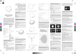
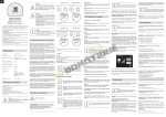
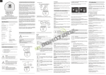
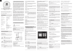
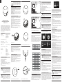
ENG
!
NOTE
When handled carelessly or used in non-specified
environment conditions, the device may not function
properly. It’s highly recommended to take all safety
precautions to ensure safety and property
protection.
VII. RESETTING THE FIBARO MOTION SENSOR
The Fibaro Motion Sensor reset erases the EPROM memory,
including all information on the Z-Wave network and the main
controller.
Fibaro Motion Sensor reset procedure:
1) Make sure the battery works and is in place.
2) Press and hold the B-button for 4-6 seconds until the LED glows
signaling the 2nd menu level.
3) Release the B-button.
4) Again, press the B-button briefly.
Successful reset will be confirmed with the LED changing colour to
red and fading.
I. GLOSSARY OF TERMS
• INCLUSION (adding a device, learning mode) - a device sends the
Z-Wave Node Info command frame allowing to add the device to the
Fibaro System (Home Center)
• EXCLUSION (removing / deleting a device) - removing a device
from the Fibaro System.
• ASSOCIATION - controling other devices within the Fibaro System
• MultiChannelAssociation - controling other multi-channel devices
within the Fibaro System.
!
II. Z-WAVE NETWORK INCLUSION
The Fibaro Motion Sensor can be included into the Z-Wave network
by using the B-button.
OPERATING MANUAL
FIBARO MOTION SENSOR
FGMS-001 V2.4
The Fibaro Motion Sensor is a universal Z-Wave multi-sensor. Along
with detecting motion the device measures the temperature and light
intensity. The sensor has a built-in accelerometer to detect any
tampering of the device. The Fibaro Motion Sensor is battery powered device and designed to be installed quckly and easily on any
surface. The LED indicator signals motion, temperature level, operating mode and can be used to see if device is within the Z-Wave
network. The motion sensor can be used for lighting scenes and
security monitoring systems.
1) Insert the battery into the Fibaro Motion Sensor. Enclosure lock is
marked with a dot. Make sure the device is located within the direct
range of the main controller.
2) Set the main controller into the learning mode (see main
controller’s operating manual).
3) Quickly, triple click the B-button - LED diode will glow blue.
4) Fibaro Motion Sensor will be detected and included in the Z-Wave
network.
5) Wait for the main controller to configure the sensor.
6) If necessary, wake up the Motion Sensor by triple clicking the
B-button.
7) LED diode will glow blue to confirm the sensor woke up, and then
wait for the main controller to configure the sensor.
VIII. OPERATING WITHIN THE Z-WAVE NETWORK
I’M DY
A
RE
Fibaro Motion Sensor has a bulit in motion detector, temperature
sensor and light intensity sensor, which make it a multi-channel
device. In the Home Center 2 menu it will be presented as three
devices, depending on the main controller software version.
!
CR123A battery, 3.6 VDC
EU directive compliance:
LVD 2006/95/WE
EMC 2004/108/WE
R&TTE 1999/5/WE
RoHS II
Recommended installation height:
2,4m
Operational Temperature:
0-40oC
Measured Temperature Range:
-20 to 100oC
Temperature Measuring
Accuracy:
0,5oC (within 0oC-40oC range)
Light Intensity Measuring Range:
0-32000 LUX
Radio Protocol:
Z-Wave
Radio Frequency:
869 MHz EU;
908 MHz US;
921 MHz ANZ;
869 MHz RU;
up to 50 m outdoors
up to 30 m indoors
(depending on terrain and
building structure)
TECHNICAL INFORMATION
- Compatible with any Z-Wave controller.
- Detects motion using a passive IR sensor.
- Measures the temperature.
- Measures the light intensity.
- Easy installation on a wall or any surface.
- Protected against tampering and theft - once vibrations are
detected, the notification is sent to the main controller.
- Alarms of movement and temperature are signaled by LED diode
blinking.
- Simple earthquake detector mode.
!
NOTE
Read this manual before attempting to install the
device. Failure to observe recommendations
included in this manual may be dangerous or cause
a violation of the law. The manufacturer, Fibar Group
Sp. z o.o., will not be held responsible for any loss or
damage resulting from not following the instructions
of operating manual.
NOTE
Work within local code height requirements for
installation of the Fibaro Smoke Sensor. Take
special precautions during installation and use tools
and equipment in perfect working order. It’s
recommended to observe ladders, lifts and other
obstacles.
B-BUTTON
3m
Diagram 3 - preparing Fibaro Motion Sensor for operation.
III. EXCLUDING SENSOR FROM THE Z-WAVE NETWORK
1) Make sure the sensor is connected to power source.
2) Set the main controller into the learn mode (see main controller’s
operating manual)
3) Quickly, triple click the B-button, located on Fibaro Motion Sensor’s enclosure.
4) LED diode will glow blue confirming the device has been excluded
from the network.
0m
7m
IV. SENSOR INSTALLATION
!
1) Include the device into the Z-Wave network (see p.II). Note that
the inclusion process may be performed ONLY in direct range of the
main controller.
2) Install the sensor’s holder in desired location.
3) If the sensor is already included in the Z-Wave network, wake it up
by triple clicking the B-button.
4) Insert the Motion Sensor in its holder.
5) Test the sensor’s operation - check whether the LED diode
indicates motion detection.
6) Test the Z-Wave network assuring the device is within range.
0m
SENSOR
STICKER
5m
Diagram 6 - Fibaro Motion Sensor’s motion detection area.
VI. INSTALLATION NOTES
Diagram 4 - Fibaro Motion Sensor installation.
NOTE
Association allows for direct communication
between Z-Wave network devices. Main controller
does not take part in such communication. Using this
mechanism, Fibaro Motion Sensor may
communicate with other devices even when the
main controller is damaged, e.g. in case of a fire.
Fibaro Motion Sensor allows for the association of three groups.
1st Association Group is assigned to the device status - sending
the BASIC SET control frame to the associated devices having
detected motion.
2nd Association Group is assigned to the tamper alarm. Alarm
frame will be sent to the associated devices once tampering is
detected.
3rd Association Group reports the device status and allows for
assigning a single device only (the main controller by default - the
device reports its status to the main controller). It’s not recommended to modify this association group.
7m
Diagram 2 - Motion detector, light sensor, LED diode.
IX. ASSOCIATIONS
By using association with Fibaro’s devices the Fibaro Motion Sensor
may control another Z-Wave network device, e.g. a Dimmer, Relay
Switch, Roller Shutter, RGBW Controller, Wall Plug, or a scene
(scene only through the Home Center 2 main controller).
5m
Fibaro Motion Sensor cannot be pointed at any source of heat (e.g.
radiators, fireplaces, cookers, etc.) or at any source of light (direct
sunlight, lamps).
It’s not recommended to install the motion sensor in places prone to
drafts. Sensor can be mounted using screw or the sticker.
XII. LED VISUAL INDICATORS AND SETTINGS
The Fibaro Motion Sensor is equipped with a LED diode for
indicating sensor’s operating modes and alarms. In addition the LED
indicator may inform of the Z-Wave network range and the current
temperature.
LED indicator modes:
1) Motion Alarm’s colour will vary depending on the temperature. The
colour and the signaling mode can be set in parameter 80.
2) Tamper alarm is signaled with an alternating blinking in red - blue
- white.
3) The Z-Wave Node Info command frame is signaled with glowing
in blue. Node Info command frame is sent each time the device
wakes up.
To enter MENU press and hold the B-button for 3 seconds. MENU
levels will be signaled with the LED colours:
- VIOLET - Z-Wave network range tester
- YELLOW - sensor reset.
The Fibaro Motion Sensor has a built in Z-Wave network main
controller’s range tester. Follow the below instructions to test the
main controller’s range:
1) Press and hold the B-button for 2 to 4 seconds until the LED glows
violet.
2) Release the B-button.
3) Press the B-button again, briefly.
4) LED will indicate the Z-Wave network’s range (range signaling
modes described below).
5) To exit Z-Wave range test, press the B-button breifly.
Fibaro Motion Sensor’s detection area is shown in diagram #6.
Fibaro Motion Sensor has to be installed in a corner of the room or
perpendicularly to the doors.
Actual range of the sensor can be influenced by environment
conditions. Should false motion alarms be reported, check for any
moving objects within the sensor’s detection area, such as trees
blowing in the wind, cars passing by, windmills. False motion alarms
may be caused by moving masses of air and heat as well. If the
device keeps on reporting false alarms, despite eliminating all of the
above-mentioned factors, install the device in another place.
Diagram 1 - B-button.
The Fibaro Motion Sensor has a built-in accelerometer. When the
value of parameter 24 is set to 2 or 3, Z-Wave networ controller will
be informed on the Sensor’s orientation in space.
XIII. Z-WAVE RANGE TEST
Motion, temperature and light intensity values are presented in
Home Center 2 menu with the following icons:
V. DETECTION AREA AND WORKING CONDITIONS
Power Supply:
!
NOTE
Fibaro Motion Sensor capabilities will vary
depending on the Z-Wave network controller. Certain
functionalities of the Fibaro Motion Sensor may not
be supported by some controllers. To make sure
your Z-Wave network controller supports the Fibaro
Motion Sensor, get in touch with its manufacturer.
Diagram 5 - Fibaro Motion Sensor’s proximity area.
SPECIFICATIONS
Range:
NOTE
Device reset will not remove it from the Z-Wave
network main controller’s memory. Before resetting
the device, it must be excluded from the Z-Wave
network.
XI. SENSOR’S ORIENTATION IN SPACE
The Fibaro Motion Sensor allows for controlling 5 regular and 5
multichannel devices per an association group, out of which 1 field is
reserved for the Z-Wave network main controller.
X. EARTHQUAKE DETECTOR MODE
Fibaro Motion Sensor can be configured to work as a simple
earthquake detector, by setting the Parameter 24 value to 4. Reports
with scale of the vibrations (dimensionless) will be sent at the time
intervals specified in Parameter 22. First report will be sent
immediately after vibrations have been detected. The minimum
value of the vibrations, resulting in report being sent, can be defined
in Parameter 20. Once the vibrations cease, reports will stop being
sent. The Home Center 2 menu presents the earthquake detector
measurements in the following way:
Z-Wave range tester signaling modes:
LED indicator pulsing green - Fibaro Motion Sensor attempts to
extablish a direct communication with the main controller. If a direct
communication attempt fails, sensor will try to establish a routed
communication, through other modules, which will be signaled by
LED indicator pulsing yellow.
LED indicator glowing green - Fibaro Motion Sensor communicates with the main controller directly.
LED indicator pulsing yellow - Fibaro Motion Sensor tries to
establish a routed communication with the main controller through
other modules (repeaters).
LED indicator glowing yellow - Fibaro Motion Sensor communicates with the main controller through the other modules. After 2
seconds the sensor will retry to establish a direct communication
with the main controller, which will be signaled with LED blinking in
green.
LED indicator pulsing violet - Fibaro Motion Sensor does
communicate at the maximum distance of the Z-Wave network. If
connection proves successful it will be confirmed with a yellow glow.
It’s not recommended to use the sensor at the range limit.
LED indicator glowing red - Fibaro Motion Sensor is not able to
connect to the main controller directly or through another Z-Wave
network device (repeater).
XIV. BATTERY USAGE TIPS
The Fibaro Motion Sensor’s battery life is approximately 2 years at
factory default settings. The current battery level is displayed in a
Home Center 2 interface. Red battery icon means the battery needs
replacement. In order to avoid tamper detection while replacing the
battery, remove association of the 2-nd association group and
reduce tamper sensitivity (parameter 20 value set to 0). If battery
discharges quickly, please check for the following conditions which
may result in reducing the battery life:
- Wake up interval is too short - it’s recommended to lengthen the
interval.
- Temperature and light intensity reports are sent too frequently modify the advanced configuration settings to decrease the
frequency.
- If associated devices or the Z-Wave network main controller are
disconnected from the power source it will cause the sensor to
frequently attempt to reconnect to those devices which will result in
shortening the battery life.
!
NOTE
The Fibaro Motion Sensor is a battery-powered
device. Using batteries other than specified may
result in explosion. Dispose of properly, observing
environmental protection rules.
!
NOTE
The Fibaro Motion Sensor features remote software
updates. The functionality is supported by the Fibaro
Home Center 2 and may not be supported by other
controllers. During the software update process, the
sensor does NOT support alarm functions.
XV. ADVANCED CONFIGURATION
WAKE UP INTERVAL
At each wake up the Fibaro Motion Sensor communicates with the
main controller, updates parameter settings and the software if
necessary. The Motion Sensor will wake up at a defined time interval
and will ALWAYS try to communicate with the main controller
Wake Up Interval set to 0 cancels the WAKE UP command frame,
i.e. the device will have to be woke up manually, through the B
button, sending NODE INFO command frame.
Available settings: 0-65535 (0-65535 seconds).
Default setting: 7200 (7200 seconds).
Parameter size: 2 [bytes]
!
NOTE
It’s not recommended to set the value of Wake Up
interval below 10 seconds. Short wake up interval
may shorten the battery life and delay the reports or
even make them impossible.
1. MOTION SENSOR’S SENSITIVITY
The lower the value, the more sensitive the PIR sensor.
Available settings: 8 - 255
Default setting: 10
Parameter size: 1 [byte]
2. MOTION SENSOR’S BLIND TIME (INSENSITIVITY)
Period of time through which the PIR sensor is “blind” (insensitive) to
motion. After this time period the PIR sensor will be again able to
detect motion. The longer the insensitivity period, the longer the
battery life. If the sensor is required to detect motion quickly, the time
period may be shortened. The time of insensitivity should be shorter
that the time period set in parameter 6.
Available settings: 0 - 15
Formula to calculate the time: time [s] = 0.5 x (value + 1)
Default setting: 15 (8 seconds)
Parameter size: 1 [byte]
3. PIR sensor’s “PULSE COUNTER”
Sets the number of moves required for the PIR sensor to report
motion. The lower the value, the less sensitive the PIR sensor. It’s
not recommended to modify this parameter settings.
Available settings: 0 - 3
Formula to calculate the number of pulses: pulses = (value + 1)
Default setting: 1 (2 pulses)
Parameter size: 1 [byte]
4. PIR sensor’s “WINDOW TIME”
Period of time during which the number of moves set in parameter 3
must be detected in order for the PIR sensor to report motion. The
higher the value, the more sensitive the PIR sensor. It’s not
recommended to modify this parameter setting.
Available settings: 0 - 3
Formula to calculate the time: time [s] = 4 x (value + 1)
Default setting: 2 (12 seconds)
Parameter size: 1 [byte]
6. MOTION ALARM CANCELLATION DELAY
Motion alarm will be cancelled in the main controller and the
associated devices after the period of time set in this parameter. Any
motion detected during the cancellation delay time countdown will
result in the countdown being restarted. In case of small values,
below 10 seconds, the value of parameter 2 must be modified (PIR
sensor’s “Blind Time”).
Available settings: 1 - 65535
Default setting: 30 (30 seconds)
Parameter size: 2 [bytes]
8. PIR SENSOR OPERATING MODE
The parameter determines the part of day in which the PIR sensor
will be active. This parameter influences only the motion reports and
associations. Tamper, light intensity and temperature measurements
will be still active, regardless of this parameter settings.
0 - PIR sensor always active
1 - PIR sensor active during the day only
2 - PIR sensor active during the night only.
Default setting: 0
Parameter size: 1 [byte]
9. NIGHT / DAY
The parameter defines the difference between night and day, in
terms of light intensity, used in parameter 8.
Available settings: 1 - 65535
Default setting: 200 (200 lux)
Parameter size: 2 [bytes]
12. BASIC COMMAND CLASS FRAMES CONFIGURATION
The parameter determines the command frames sent in 1-st
association group, assigned to PIR sensor.
0 - BASIC ON and BASIC OFF command frames sent in Basic
Command Class.
1 - only the BASIC ON command frame sent in Basic Command
Class.
2 - only the BASIC OFF command frame sent in Basic CommandClass.
Values of BASIC ON and BASIC OFF command frames may be
modified by dedicated parameters.
Default setting: 0
Parameter size: 1 [byte]
14. BASIC ON command frame value
The value of 255 allows to turn ON a device. In case of the Dimmer,
the value of 255 means turning ON at the last memorized state, e.g.
the Dimmer turned ON at 30% and turned OFF using the value of
255, and then turned OFF, will be turned ON at 30%, i.e. the last
memorized state.
Available settings: 0 - 255
Default setting: 255
Parameter size: 1 [byte]
16. BASIC OFF command frame value
The command frame sent at the moment of motion alarm
cancellation, after the cancellation delay time, specified in parameter
6, has passed.
The value of 0 allows to turn a device OFF while the value of 255
allows to turn ON a device. In case of the Dimmer, the value of 255
means turning ON at the last memorized state, e.g. the Dimmer
turned ON at 30% and turned OFF using the value of 255, and then
turned OFF, will be turned ON at 30%, i.e. the last memorized state.
Available settings: 0 - 255
Default setting: 0
Parameter size: 1 [byte]
20. TAMPER SENSITIVITY
The parameter determines the chages in forces acting on the Fibaro
Motion Sensor resulting in tamper alarm beig reported - g-force
acceleration.
Available settigs: 0 - 122 (0.08 - 2g; multiply by 0.016g; 0 = tamper
inactive)
Default setting: 15 (0.224g)
Parameter size: 1 [byte]
22. TAMPER ALARM CANCELLATION DELAY
Time period after which a tamper alarm will be cacelled. Another
tampering detected durig the countdown to cancellation will not
extend the delay.
Available settings: 1 - 65535
Default setting: 30 (seconds)
Parameter size: 2 [bytes]
24. TAMPER OPERATING MODES
The parameter determines the behaviour of tamper and how it
reports.
0 – Tamper alarm is reported in Sensor Alarm command class /
Cancellation is not reported.
1 – Tamper alarm is reported in Sensor Alarm command class /
Cancellation is reported in Sensor Alarm commad class after the
time period set in parameter 22 (Tamper Alarm Cancellation Delay)
2 - Tamper alarm is reported in Sensor Alarm command class /
Cancellation is not reported.
Sensor’s orientation in space is reported in Fibar Commad Class
after the time period set in paramer 22.
3 - Tamper alarm is reported in Sensor Alarm command class /
Cancellation is reported in Sensor Alarm commad class after the
time period set in parameter 22. Sensor’s orientation in space is
reported in Fibar Commad Class after the time period set in paramer
22.
4 - The maximum level of vibrations recorded in the time period set
in parameter 22 is reported. Reports stop being sent when the
vibrations cease. The reports are sent in Sensor Alarm command
class. Value displayed in the “value” field (0 - 100) depends on the
vibrations force. Reports to the association groups are sent using
Sensor Alarm command class
Available settings: 0 or 255
Default setting: 0
Parameter size: 1 [byte]
26. TAMPER ALARM BROADCAST MODE
The parameter determines whether the tamper alarm frame will or
will not be sent in broadcast mode. Alarm frames sent in broadcast
mode may be received by all of the devices within communication
range (if they accept such frames).
0 - Tamper alarm is not sent in broadcast mode.
1 - Tamper alarm sent in broadcast mode.
Default setting: 0
Parameter size: 1 [byte]
40. ILLUMINATION REPORT THRESHOLD
The parameter determines the change in light intensity level
resulting in illumination report being sent to the main controller.
Available settings: 0 - 65535 (1 - 65535 lux; 0 = reports are not
sent)
Default setting: 200 (200 lux)
Parameter size: 2 [byte]
42. ILLUMINATION REPORTS INTERVAL
Time interval between consecutive illumination reports. The reports
are sent even if there are no changes in the light intensity.
Available settings: 0 - 65535 (1 - 65535 seconds; 0 = reports are
not sent)
Default setting: 0 (no reports)
Parameter size: 2 [bytes]
!
NOTE
Frequent reports will shorten the battery life.
Parameter value under 5 may result in blocking the
temperature reports.
60. TEMPERATURE REPORT THRESHOLD
The parameter determines the change in level of temperature
resulting in temperature report being sent to the main controller.
Available settings: 0 - 255 (0.1 - 25.5oC; 0 = reports are not sent)
Default setting: 10 (1oC)
Parameter size: 1 [byte]
62. INTERVAL OF TEMPERATURE MEASURING
The parameter determines how often the temperature will be
measured. The shorter the time, the more frequently the temperature
will be measured, but the battery life will shorten.
Available settings: 0 - 65535 (1 - 65535 seconds; 0 = temperature
will not be measured)
Default setting: 900 (900 seconds)
Parameter size: 2 [bytes]
!
NOTE
Frequent reports will shorten the battery life.
Parameter value under 5 may result in blocking the
ilumination reports.
64. TEMPERATURE REPORTS INTERVAL
The parameter determines how often the temperature reports will be
sent to the main controller.
Available settings: 0 - 65535 (1 - 65535 sekund; 0 = reports are not
sent)
Default setting: 0
Parameter size: 2 [byte]
66. TEMPERATURE OFFSET
The value to be added to the actual temperature, measured by the
sensor (temperature compensation).
Available settings: 0 - 100 (0 to 100oC) or 64536 - 65535 (-100 to
-0.10oC)
Default setting: 0
Parameter size: 2 [bytes]
80. LED SIGNALING MODE
The parameter determines the way in which LED diode behaves
after motion has been detected.
Values from 1 to 9 = single long blink at the moment of reporting
motion. No other motion will be indicated until alarm is cancelled.
Values from 10 to 18 = single long blink at the moment of reporting
motion and one short blink each time the motion is detected again.
Values from 19 to 26 = single long blink at the moment of reporting
motion and two short blinks each time the motion is detected again.
0. LED inactive.
1. LED colour depends on the temperature. Set by parameters 86
and 87.
2. Flashlight mode - LED glows in white for 10 seconds.
3. White.
4. Red.
5. Green.
6. Blue.
7. Yellow.
8. Cyan.
9. Magenta.
10. LED colour depends on the temperature. Set by parameters
86 and 87.
11. Flashlight mode - LED glows in white through 10 seconds.
Each next detected motion extends the glowing by next 10
seconds.
12. White.
13. Red.
14. Green.
15. Blue.
16. Yellow.
17. Cyan
18. Magenta
19. LED colour depends on the temperature. Set by parameters
86 and 87.
20. White
21. Red
22. Green
23. Blue
24. Yellow
25. Cyan
26. Magenta
Default setting: 10
Parameter size: 1 [byte]
81. LED BRIGHTNESS
The parameter determines the brightness of LED when indicating
motion.
Available settings: 0 - 100 (1 - 100%; 0 = brightness determined by
the ambient lighting - see parameters 82 and 83)
Default setting: 50
Parameter size: 1 [byte]
82. AMBIENT ILLUMINATION LEVEL BELOW WHICH LED
BRIGHTNESS IS SET TO 1%
The parameter is relevant only when the parameter 81 is set to 0.
Available settings: 0 to parameter 83 value
Default setting: 100 (100 lux)
Parameter size: 2 [bytes]
83. AMBIENT ILLUMINATION LEVEL ABOVE WHICH LED
BRIGHTNESS IS SET TO 100%
The parameter is relevant only when the parameter 81 is set to 0.
Available settings: parameter 82 value to 65535
Default setting: 1 000 (1 000 lux)
Parameter size: 2 [bytes]
!
NOTE
The value of the parameter 83 must be higher than
the value of the parameter 82.
86. MINIMUM TEMPERATURE RESULTING IN BLUE LED
ILLUMINATION
This parameter is relevant only when parameter 80 has been
properly configured.
Available settings: 0 to parameter 87 value (degrees celsius)
Default setting: 18 (18oC)
Parameter size: 1 [byte]
87. MAXIMUM TEMPERATURE RESULTING IN RED LED
ILLUMINATION
This parameter is relevant only when parameter 80 has been
properly configured.
Available settings: parameter 86 value to 255 (degrees celsius)
Default setting: 28 (28oC)
Parameter size: 1 [byte]
89. LED INDICATING TAMPER ALARM
Indicating mode resembles a police car (white, red and blue).
0 - LED does not indicate tamper alarm.
1 - LED indicates tamper alarm.
Default setting: 1
Parameter size: 1 [byte]
XVI. GUARANTEE
1. The Guarantee is provided by FIBAR GROUP Sp. z o.o.
(hereinafter "Manufacturer"), based in Poznan, ul. Lotnicza 1;
60-421 Poznan, entered in the register of the National Court
Register kept by the District Court in Poznań, VIII Economic
Department of the National Court Register, no. 370151, NIP
7811858097, REGON: 301595664.
2. The Manufacturer is responsible for equipment malfunction
resulting from physical defects (manufacturing or material) of the
Device for 12 months from the date of its purchasing.
3. During the Guarantee period, the Manufacturer shall remove any
defects, free of charge, by repairing or replacing (at the sole
discretion of the Manufacturer) any defective components of the
Device with new or regenerated components, that are free of
defects. When the repair impossible, the Manufacturer reserves the
right to replace the device with a new or regenerated one, which
shall be free of any defects and its condition shall not be worse than
the original device owned by the Customer.
4. In special cases, when the device cannot be replaced with the
device of the same type (e.g. the device is no longer available in the
commercial offer), the Manufacturer may replace it with a different
device having technical parameters similar to the faulty one. Such
activity shall be considered as fulfilling the obligations of the
Manufacturer. The Manufacturer shall not refund money paid for the
device.
5. The holder of a valid guarantee shall submit a guarantee claim
through the guarantee service. Remember: before you submit a guarantee claim, contact our technical support using telephone or
e-mail. More than 50% of operational problems is resolved remotely,
saving time and money spent to initiating guarantee procedure. If
remote support is insufficient, the Customer shall fill the guarantee
claim form (using our website - www.fibargroup.com) in order to
obtain claim authorization. When the guarantee claim form is submitted correctly, the Customer shall receive the claim confirmation
with an unique number (Return Merchandise Authorization -RMA).
6. The claim may be also submitted by telephone. In this case, the
call is recorded and the Customer shall be informed about it by a
consultant before submitting the claim. Immediately after submitting
the claim, the consultant shall provide the Customer with the claim
number (RMA-number).
7. When the guarantee claim form is submitted correctly, a
representative of the Authorised Guarantee Service (hereinafter as
"AGS") shall contact the Customer.
8. Defects revealed within the guarantee period shall be removed
not later than 30 days from the date of delivering the Device to AGS.
The guarantee period shall be extended by the time in which the
Device was kept by AGS.
9. The faulty device shall be provided by the Customer with complete
standard equipment and documents proving its purchase.
10. Parts replaced under the guarantee are the property of the
Manufacturer. The guarantee for all parts replaced in the guarantee
process shall be equal to the guarantee period of the original device.
The guarantee period of the replaced part shall not be extended.
11. Costs of delivering the faulty device shall be borne by the
Customer. For unjustified service calls, the Service may charge the
Customer with travel expenses and handling costs related to the
case.
12. AGS shall not accept a complaint claim only when:
12. AGS shall not accept a complaint claim only when:
• the Device was misused or the manual was not observed,
• the Device was provided by the Customer incomplete, without
accessories or
nameplate,
• it was determined that the fault was caused by other reasons than
a material or
manufacturing defect of the Device
• the guarantee document is not valid or there is no proof of
purchase,
13. The Manufacturer shall not be liable for damages to property
caused by defective device. The Manufacturer shall not be liable for
indirect, incidental, special, consequential or punitive damages, or
for any damages, including, inter alia, loss of profits, savings, data,
loss of benefits, claims by third parties and any property damage or
personal injuries arising from or related to the use of the Device.
14. The guarantee shall not cover:
• mechanical damages (cracks, fractures, cuts, abrasions, physical
deformations caused by impact, falling or dropping the device or
other object, improper use or not observing the operating manual);
• damages resulting from external causes, e.g.: flood, storm, fire,
lightning, natural disasters, earthquakes, war, civil disturbance, force
majeure, unforeseen accidents, theft, water damage, liquid leakage,
battery spill, weather conditions, sunlight, sand, moisture, high or low
temperature, air pollution;
• damages caused by malfunctioning software, attack of a computer
virus, or by failure to update the software as recommended by the
Manufacturer;
• damages resulting from: surges in the power and/or telecommunication network, improper connection to the grid in a manner
inconsistent with the operating manual, or from connecting other
devices not recommended by the Manufacturer.
• damages caused by operating or storing the device in extremely
adverse conditions, i.e. high humidity, dust, too low (freezing) or too
high ambient temperature. Detailed permissible conditions for
operating the Device are defined in the operating manual;
• damages caused by using accessories not recommended by the
Manufacturer
• damages caused by faulty electrical installation of the Customer,
including the use of incorrect fuses;
• damages caused by Customer's failure to provide maintenance
and servicing activities defined in the operating manual;
• damages resulting from the use of spurious spare parts or
accessories improper for given model, repairing and introducing
alterations by unauthorized persons;
• defects caused by operating faulty Device or accessories.
15. The scope of the guarantee repairs shall not include periodic
maintenance and inspections, in particular cleaning, adjustments,
operational checks, correction of errors or parameter programming
and other activities that should be performed by the user (Buyer).
The guarantee shall not cover natural wear and tear of the Device
and its components listed in the operating manual and in technical
documentation as such elements have a defined operational life.
16. If a defect is not covered by the guarantee, the Manufacturer
reserves the right to remove such defect at its sole discretion,
repairing the damaged or destroyed parts or providing components
necessary for repair or replacement.
17. This guarantee shall not exclude, limit or suspend the Customer
rights when the provided product is inconsistent with the purchase
agreement.
i
This Device may be used with all devices
certified with Z-Wave certificate and should be
compatible with such devices produced by
other manufacturers.
Any device compatible with Z-Wave may be
added to Fibaro system.
FIBAR GROUP
FIBARO
In case of any technical questions contact customer service centre in
your country.
www.fibaro.com