1
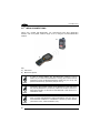
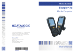
Mobile Computer
www.datalogic.com
© 2014 Datalogic ADC S.r.l. All rights reserved.
Datalogic and the Datalogic logo are registered
trademarks of Datalogic S.p.A. In many countries,
including the U.S.A. and the E.U.
Datalogic ADC S.r.l.
Via S. Vitalino, 13
40012 Lippo di Calderara di Reno
Bologna - Italy
Telephone: (+39) 051-3147011
Fax: (+39) 051-3147561
User’s Manual
822001750
09/14
Datalogic ADC S.r.l.
Via S. Vitalino, 13
40012 Lippo di Calderara di Reno
Bologna - Italy
Telephone: (+39) 051-3147011
Fax: (+39) 051-3147205
©2014 Datalogic ADC S.r.l.
An Unpublished Work - All rights reserved. No part of the contents of this documentation or
the procedures described therein may be reproduced or transmitted in any form or by any
means without prior written permission of Datalogic ADC, Inc. or its subsidiaries or affiliates
("Datalogic" or “Datalogic ADC”). Owners of Datalogic products are hereby granted a nonexclusive, revocable license to reproduce and transmit this documentation for the
purchaser's own internal business purposes. Purchaser shall not remove or alter any
proprietary notices, including copyright notices, contained in this documentation and shall
ensure that all notices appear on any reproductions of the documentation. Should future
revisions of this manual be published, you can acquire printed versions by contacting your
Datalogic representative. Electronic versions may either be downloadable from the Datalogic
website (www.datalogic.com) or provided on appropriate media. If you visit our website and
would like to make comments or suggestions about this or other Datalogic publications,
please let us know via the "Contact Datalogic" page.
Disclaimer
Datalogic has taken reasonable measures to provide information in this manual that is
complete and accurate, however, Datalogic reserves the right to change any specification at
any time without prior notice. Datalogic and the Datalogic logo are registered trademarks of
Datalogic S.p.A. in many countries, including the U.S.A. and the E.U.
Falcon and the Falcon logo are trademarks of Datalogic ADC S.r.l.
All other brand and product names may be trademarks of their respective owners.
Patents
See www.patents.datalogic.com for patent list.
This product is covered by one or more of the following patents:
Design patents: AU329643, EP001180673, USD622726, ZL200930383849.1
Utility patents: EP0789315B1, EP1128315B1, EP1396811B1, EP1413971B1, US5686716,
US5992740, US6412698, US6415978, US6454168, US6478224, US6513714, US6561427,
US6585157, US6808114, US6997385, US7108170, US7299975, US7387246.
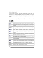
CONTENTS
REFERENCES ............................................................................................ VI
Conventions ..................................................................................................vi
Reference Documentation ............................................................................vi
Services and Support ....................................................................................vi
GENERAL VIEW ........................................................................................ VII
1
1.1
1.2
1.3
1.4
1.4.1
1.5
INTRODUCTION .......................................................................................... 1
Falcon X3+ Description ................................................................................. 1
Available Models ........................................................................................... 3
Package Contents ......................................................................................... 7
Inserting MicroSD Card ................................................................................. 8
Removing the MicroSD Card ........................................................................ 9
Accessories................................................................................................. 10
2
2.1
2.2
2.3
BATTERIES AND MAINTENANCE ........................................................... 11
Charging the Battery Pack .......................................................................... 11
Replacing the Battery Pack ......................................................................... 14
Cleaning the Mobile Computer.................................................................... 18
3
3.1
3.2
3.3
3.4
3.5
3.6
CONNECTIONS ......................................................................................... 19
USB Connection ......................................................................................... 19
Connection to USB Peripherals .................................................................. 21
RS232 Connection ...................................................................................... 23
WLAN Connection ...................................................................................... 24
WPAN Connections .................................................................................... 26
Wireless and Radio Frequencies Warnings ................................................ 27
4
4.1
4.1.1
4.1.2
4.2
4.3
4.3.1
4.3.2
4.4
4.4.1
4.4.2
4.4.3
4.4.4
4.5
4.5.1
4.5.2
USE AND FUNCTIONING .......................................................................... 29
Startup ........................................................................................................ 29
Using the Stylus .......................................................................................... 30
Touch Gestures .......................................................................................... 31
Windows CE Touch Screen Calibration ...................................................... 32
Data Capture............................................................................................... 33
Laser Data Capture ..................................................................................... 34
Imager Data Capture................................................................................... 36
Description of the Keys ............................................................................... 38
52-Key Alphanumeric Keyboard ................................................................. 38
52-Key Terminal Emulation 5250 Keyboard................................................ 40
Numeric Keyboard ...................................................................................... 42
Resetting the Falcon X3+............................................................................ 44
Status Indicators ......................................................................................... 46
LED Status .................................................................................................. 46
Taskbar ....................................................................................................... 47
iii
4.6
4.6.1
4.6.2
4.6.3
4.6.4
4.6.5
4.6.6
4.6.7
4.6.8
4.7
4.7.1
4.7.2
4.8
4.8.1
4.8.2
4.8.3
4.9
4.10
4.10.1
4.10.2
4.10.3
4.10.4
4.10.5
4.11
4.12
4.12.1
4.13
4.13.1
4.13.2
4.13.3
4.13.4
Control Panel .............................................................................................. 48
Data Capture Configuration ........................................................................ 49
Decoding Configuration pages .................................................................... 49
DL Buttons .................................................................................................. 57
Triggers ....................................................................................................... 61
Application Switcher .................................................................................... 62
Persistent Registry ...................................................................................... 63
Wireless Communications........................................................................... 66
Stylus Calibration ........................................................................................ 71
Audio Settings ............................................................................................. 73
Connecting to Other Computers ................................................................. 75
Windows Mobile® Device Center................................................................ 75
®
Bluetooth Manager Device Setup .............................................................. 77
Datalogic Firmware Utility ........................................................................... 84
Retrieving a Firmware Image Update ......................................................... 84
Installing DFU on the Host PC .................................................................... 85
Updating the Firmware ................................................................................ 86
Datalogic Configuration Utility ..................................................................... 87
Datalogic Desktop Utility ............................................................................. 88
Administrative Options (Admin tab)............................................................. 89
Locked Web Browser Options (LockedWeb tab) ........................................ 92
Status Icons Options (Status Tab) .............................................................. 97
Windows Controls ....................................................................................... 98
AppSelector Options (AppSelect tab)........................................................ 100
AppSelector (Application Selector) ........................................................... 103
Locked Web Browser ................................................................................ 104
Locked Web Browser Special Metatags ................................................... 106
Autostart.................................................................................................... 110
Installing CAB Files ................................................................................... 110
How AutoStart Uses Wceload ................................................................... 111
Interactive CAB Install ............................................................................... 112
Autostart.ini ............................................................................................... 112
5
5.1
5.2
TECHNICAL FEATURES ......................................................................... 118
Technical Data .......................................................................................... 118
Reading Diagrams .................................................................................... 122
6
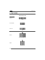
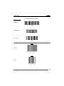
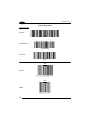
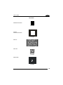
TEST CODES ........................................................................................... 126
REGULATORY INFORMATION ............................................................... 130
General Safety Rules ................................................................................ 130
Power Supply ............................................................................................ 130
Laser Safety .............................................................................................. 131
LED Class ................................................................................................. 137
Radio Compliance..................................................................................... 138
FCC Compliance ....................................................................................... 141
iv
Industry Canada Compliance .................................................................... 143
SAR Compliance....................................................................................... 145
WEEE Compliance ................................................................................... 146
GLOSSARY .............................................................................................. 148
INDEX ....................................................................................................... 152
v
1
REFERENCES
CONVENTIONS
This manual uses the following conventions:
“User” refers to anyone using a Falcon X3+ mobile computer.
“Mobile computer” and "Falcon X3+" refer to the Falcon X3+ mobile computer.
“You” refers to the System Administrator or Technical Support person using this
manual to install, configure, operate, maintain or troubleshoot an Falcon X3+ mobile
computer.
“Single Dock” refers to the Falcon X3+ Single Slot Dock.
The label artworks may be only a draft. Refer to the product labels for more precise
information.
REFERENCE DOCUMENTATION
For further information regarding Falcon X3+ refer to the SDK Help on-Line.
SERVICES AND SUPPORT
Datalogic provides several services as well as technical support through its website.
Please check our website at www.datalogic.com under “Support & Services”, then
“Automatic Data Capture”, and click on the links indicated for further information
including:
-
Downloads
- Manuals for the latest versions of user manuals and product guides.
- Software & Utilities for the latest firmware release for your product. You can
also click on the following link for direct access to this section:
www.datalogic.com/products_updates.
-
Service Program for warranty extensions and maintenance agreements.
-
Repair Centers for a list of authorised repair centers.
-
Technical Support Automatic Data Capture email form to contact our
technical support.
vi
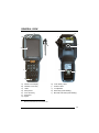
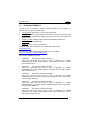
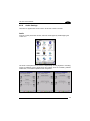
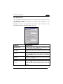
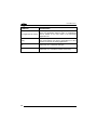
GENERAL VIEW
C
H
B
I
J
G
A
E
K
F
L
D
A)
B)
C)
D)
E)
F)
G)
∗
QVGA Color Display ∗
ON/OFF Power Key
LEDs
Microphone
Front Scan Key
Keyboard
Stylus
H)
I)
J)
K)
L)
Laser Safety Label
Product Label
Loudspeaker
Reset Key (under battery)
MicroSD Card Slot (under battery)
Remove protective film cover before use
vii
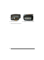
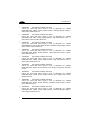
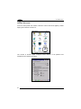
1
M
N
M) Data Capture Window*
∗
viii
Remove protective film cover before use
N) Handylink™ Connector (host/slave)
INTRODUCTION
1
1.1
1
INTRODUCTION
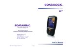
FALCON X3+ DESCRIPTION
The new Datalogic Falcon X3+ mobile computer delivers the ultimate in ruggedness,
ergonomics, computing and data capture technologies. Falcon X3+ options provide a
tailored solution for demanding environments needing real time transaction visibility.
The Falcon X3+ delivers rugged construction, laser and image data capture, along
with real time communications in a product that is effortless to develop for, deploy
and manage.
Enterprises rely on accurate inventories to both plan and manage activities. Four
data capture options optimize the Falcon X3+ to the application. A laser scanner
tackles high volume environments where speed is essential to receiving and shipping
operations. The imager captures linear, stacked and 2D codes to reduce failed reads
due to damaged and poor quality barcodes. An optional camera takes pictures for the
documentation of damaged or returned goods. Datalogic’s patented Green Spot
good read feedback reduces errors in both noisy and quiet environments. For
applications like cross docking where bar codes can be close at hand or far away, an
auto ranging laser and an extended long range imager offer aggressive scanning
solutions.
The parallel computer architecture of the Falcon X3 melds the strengths of an
XScale™ PXA310 microprocessor with a Cortex-M3 coprocessor. This combination
gears the device for real time information management. Memory of 256 MB RAM / 1
GB Flash accommodates multiple simultaneous applications, for managing large
databases or enabling off-line autonomy of thick applications. A Micro SD Card Slot
provides a simple way for users to increase memory storage capacity as needed.
The Falcon X3+ tailors itself to the information technology practices of the enterprise
through either the Microsoft Windows CE 6.0 or Microsoft Windows Mobile 6.5
operating system.
As information is collected the Falcon X3 turns to the task of communication via a
Summit IEEE 802.11 a/b/g/n radio. Complimented by a CCX v4 certification from
Cisco, the Falcon X3+ provides infrastructure compatibility focused on enterprise
requirements for encrypted communication and seamless roaming. Voice
applications leverage the internet protocol connection for hands-free voice picking
and push to talk communications. Bluetooth® Wireless Technology connects
headsets, printers and other peripherals eliminating cumbersome wires. An extensive
accessory offering accommodates existing installation needs for USB, RS232,
modem or Ethernet communications.
1
1
1 FALCON™ X3+
The Falcon X3+ comes in two form factors to tackle the differing scanning intensities
found in an enterprise. A pistol grip version with numeric keypad tackles the high
volume scan and quantity entry found at the receiving dock. While a hand held with
alpha numeric keypad better suits the lighter pick and pack duty of preparing goods
for shipment. The Falcon’s low weight balances a large 3.5” display with a full size
keyboard and a single piece 5200 mAh battery into both of these packages.
The Falcon X3+ must do more than function for a full shift, it must survive daily abuse
and trauma. The new Falcon X3+ survives drops from 6 feet (1.8 meter) to concrete.
Coupled with an IP65 sealing against water and dust, and featuring Gorilla Glass 3 ®
on the scan window, allows the Falcon X3+ to literally take an industrial pounding.
Plastic key caps with metal snap dome actuation withstand not only the abusive
environment but the heavy use found in third party logistics centers, literally millions
of cycles per year.
Falcon delivers Datalogic’s trademark ergonomics in a contoured package. An
arched pistol grip handle and ergonomic trigger make the rapid receiving of goods
comfortable throughout the day. Falcon X3+ numeric and alphanumeric keyboards
use a phone key layout placing numeric keys at the device top with navigation, scan
and enter keys. This highly functional layout places high use keys at the user’s finger
tips. Maximized key sizes drive additional user efficiency with or without gloves. A
choice of crystal clear full VGA and QVGA displays and the back lit keyboard make
the Falcon X3+ readable in dark back corners or full sunlight.
The Falcon X3+ leverages Datalogic’s software development kit (SDK) for creating
applications. The Datalogic™ SDK provides a set of libraries allowing easy
application development using C++, .NET and Java programming languages. Both
MCL Collection and Wavelink® Studio™ offer additional solutions to enable
development. For terminal emulation environments available tools include the
Wavelink Industrial Browser™, Wavelink Terminal Emulation, and Wavelink
Speakeasy.
Wavelink Avalanche™ device management tools make the Falcon X3+ an easy
device to both deploy and maintain. Datalogic Desktop, Configuration and Firmware
Utilities deliver unprecedented ability to customize and update device configuration to
the use environment or process. For small or remote installations, Scan to Configure
provides simple barcodes that anyone can use to configure the Falcon X3+. Wavelink
Remote Control allows an administrator to remotely diagnose and remedy both
applications and device settings. For added security the Falcon X3+ can be
implemented with Wavelink CE Secure and Wavelink Certificate Manager.
2
INTRODUCTION
1.2
1
AVAILABLE MODELS
The Falcon X3+ is available in different models depending on the options it is
equipped with. All options are listed below:
•
communication options: 802.11 a/b/g/n radio, Bluetooth®
•
data capture options: high performance laser with green spot, 2D imager with
green spot, 2D extended range imager (XLR) with green spot, auto ranging laser
(XLR), camera
•
operating system: Windows CE 6.0, Windows Embedded Handheld 6.5
•
form factor: hand held, pistol grip
•
keyboard options: numeric, alphanumeric.
For further details about the Falcon X3+ models refer to the web site:
www.datalogic.com.
For further information regarding Windows CE refer to the website:
http://www.microsoft.com/windowsembedded.
The currently available models are:
•
945200030
FALCONX3+ 00A0HP-2N0-CEU1
Falcon X3+ Hand held, 802.11 a/b/g /n CCX v4, Bluetooth v2.1, 256MB
RAM/1GB Flash, QVGA, 29-Key Numeric, High Performance Laser w Green
Spot, Windows CE 6.0
•
945200031
FALCONX3+ 00A0WI-2N0-CEU1
Falcon X3+ Hand held, 802.11 a/b/g /n CCX v4, Bluetooth v2.1, 256MB
RAM/1GB Flash, QVGA, 29-Key Numeric, Standard Range Imager w Green
Spot, Windows CE 6.0
•
945200032
FALCONX3+ 00A0HP-2N1-MEN1
Falcon X3+ Hand held, 802.11 a/b/g /n CCX v4, Bluetooth v2.1, 256MB
RAM/1GB Flash, VGA, 29-Key Numeric, High Performance Laser w Green Spot,
Camera 3.1MP, WEHH 6.5
•
945200033
FALCONX3+ 00A0WI-2N1-MEN1
Falcon X3+ Hand held, 802.11 a/b/g /n CCX v4, Bluetooth v2.1, 256MB
RAM/1GB Flash, VGA, 29-Key Numeric, Standard Range Imager w Green Spot,
Camera 3.1MP, WEHH 6.5
•
945200034
FALCONX3+ 00A0HP-2F0-CEU1
Falcon X3+ Hand held, 802.11 a/b/g /n CCX v4, Bluetooth v2.1, 256MB
RAM/1GB Flash, QVGA, 52-Key Alpha Numeric, High Performance Laser w
Green Spot, Windows CE 6.0
3
1
1 FALCON™ X3+
•
945200035
FALCONX3+ 00A0WI-2F0-CEU1
Falcon X3+ Hand held, 802.11 a/b/g /n CCX v4, Bluetooth v2.1, 256MB
RAM/1GB Flash, QVGA, 52-Key Alpha Numeric, Standard Range Imager w
Green Spot, Windows CE 6.0
•
945200036
FALCONX3+ 00A0HP-2F1-MEN1
Falcon X3+ Hand held, 802.11 a/b/g /n CCX v4, Bluetooth v2.1, 256MB
RAM/1GB Flash, VGA, 52-Key Alpha Numeric, High Performance Laser w
Green Spot, Camera 3.1MP, WEHH 6.5
•
945200037
FALCONX3+ 00A0WI-2F1-MEN1
Falcon X3+ Hand held, 802.11 a/b/g /n CCX v4, Bluetooth v2.1, 256MB
RAM/1GB Flash, VGA, 52-Key Alpha Numeric, Standard Range Imager w Green
Spot, Camera 3.1MP, WEHH 6.5
•
945250051
FALCONX3+ 00A0HP-3N0-CEU1
Falcon X3+ Pistol Grip, 802.11 a/b/g /n CCX v4, Bluetooth v2.1, 256MB
RAM/1GB Flash, QVGA, 29-Key Numeric, High Performance Laser w Green
Spot, Windows CE 6.0
•
945250052
FALCONX3+ 00A0HP-3F0-CEU1
Falcon X3+ Pistol Grip, 802.11 a/b/g /n CCX v4, Bluetooth v2.1, 256MB
RAM/1GB Flash, QVGA, 52-Key Alpha Numeric, High Performance Laser w
Green Spot, Windows CE 6.0
•
945250053
FALCONX3+ 00A0XL-3N0-CEU1
Falcon X3+ Pistol Grip, 802.11 a/b/g /n CCX v4, Bluetooth v2.1, 256MB
RAM/1GB Flash, QVGA, 29-Key Numeric, Auto ranging Laser (XLR), Windows
CE 6.0
•
945250054
FALCONX3+ 00A0XL-3F0-CEU1
Falcon X3+ Pistol Grip, 802.11 a/b/g /n CCX v4, Bluetooth v2.1, 256MB
RAM/1GB Flash, QVGA, 52-Key Alpha Numeric, Auto ranging Laser (XLR),
Windows CE 6.0
•
945250055
FALCONX3+ 00A0WI-3N0-CEU1
Falcon X3+ Pistol Grip, 802.11 a/b/g /n CCX v4, Bluetooth v2.1, 256MB
RAM/1GB Flash, QVGA, 29-Key Numeric, Standard Range Imager w Green
Spot, Windows CE 6.0
•
945250056
FALCONX3+ 00A0WI-3F0-CEU1
Falcon X3+ Pistol Grip, 802.11 a/b/g /n CCX v4, Bluetooth v2.1, 256MB
RAM/1GB Flash, QVGA, 52-Key Alpha Numeric, Standard Range Imager w
Green Spot, Windows CE 6.0
4
INTRODUCTION
1
•
945250057
FALCONX3+ 00A0LR-3N0-CEU1
Falcon X3+ Pistol Grip, 802.11 a/b/g /n CCX v4, Bluetooth v2.1, 256MB
RAM/1GB Flash, QVGA, 29-Key Numeric, Extended Range Imager (XLR),
Windows CE 6.0
•
945250058
FALCONX3+ 00A0LR-3F0-CEU1
Falcon X3+ Pistol Grip, 802.11 a/b/g /n CCX v4, Bluetooth v2.1, 256MB
RAM/1GB Flash, QVGA, 52-Key Alpha Numeric, Extended Range Imager (XLR),
Windows CE 6.0
•
945250059
FALCONX3+ 00A0HP-3N1-MEN1
Falcon X3+ Pistol Grip, 802.11 a/b/g /n CCX v4, Bluetooth v2.1, 256MB
RAM/1GB Flash, VGA, 29-Key Numeric, High Performance Laser w Green Spot,
Camera 3.1MP, WEHH 6.5
•
945250060
FALCONX3+ 00A0HP-3F1-MEN1
Falcon X3+ Pistol Grip, 802.11 a/b/g /n CCX v4, Bluetooth v2.1, 256MB
RAM/1GB Flash, VGA, 52-Key Alpha Numeric, High Performance Laser w
Green Spot, Camera 3.1MP, WEHH 6.5
•
945250061
FALCONX3+ 00A0XL-3N1-MEN1
Falcon X3+ Pistol Grip, 802.11 a/b/g /n CCX v4, Bluetooth v2.1, 256MB
RAM/1GB Flash, VGA, 29-Key Numeric, Auto ranging Laser (XLR), Camera
3.1MP, WEHH 6.5
•
945250062
FALCONX3+ 00A0XL-3F1-MEN1
Falcon X3+ Pistol Grip, 802.11 a/b/g /n CCX v4, Bluetooth v2.1, 256MB
RAM/1GB Flash, VGA, 52-Key Alpha Numeric, Auto ranging Laser (XLR),
Camera 3.1MP, WEHH 6.5
•
945250063
FALCONX3+ 00A0WI-3N1-MEN1
Falcon X3+ Pistol Grip, 802.11 a/b/g /n CCX v4, Bluetooth v2.1, 256MB
RAM/1GB Flash, VGA, 29-Key Numeric, Standard Range Imager w Green Spot,
Camera 3.1MP, WEHH 6.5
•
945250064
FALCONX3+ 00A0WI-3F1-MEN1
Falcon X3+ Pistol Grip, 802.11 a/b/g /n CCX v4, Bluetooth v2.1, 256MB
RAM/1GB Flash, VGA, 52-Key Alpha Numeric, Standard Range Imager w Green
Spot, Camera 3.1MP, WEHH 6.5
•
945250065
FALCONX3+ 00A0LR-3N1-MEN1
Falcon X3+ Pistol Grip, 802.11 a/b/g /n CCX v4, Bluetooth v2.1, 256MB
RAM/1GB Flash, VGA, 29-Key Numeric, Extended Range Imager (XLR),
Camera 3.1MP, WEHH 6.5
5
1
•
6
1 FALCON™ X3+
945250066
FALCONX3+ 00A0LR-3F1-MEN1
Falcon X3+ Pistol Grip, 802.11 a/b/g /n CCX v4, Bluetooth v2.1, 256MB
RAM/1GB Flash, VGA, 52-Key Alpha Numeric, Extended Range Imager (XLR),
Camera 3.1MP, WEHH 6.5
INTRODUCTION
1.3
1
PACKAGE CONTENTS
The Falcon X3+ package contains:
−
1 Falcon X3+ mobile computer
−
1 rechargeable battery pack
−
1 blank keypad overlay
−
1 Falcon X3+ Quick Start Guide
−
1 Wavelink Avalanche Insert
−
1 End User License Agreement (EULA) Sheet
Accessories necessary for the Falcon X3+ connection to the host computer and to
the network are packaged separately: the cradle and/or one or more connection
cables.
Remove all the components from their packaging; check their integrity and compare
them with the packing documents.
Keep the original packaging for use when sending products to the
technical assistance center. Damage caused by improper
packaging is not covered under the warranty.
CAUTION
Rechargeable battery packs are not initially charged. Therefore the
first operation to perform is to charge them. See paragraph 2.1.
NOTE
7
1 FALCON™ X3+
1
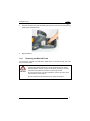
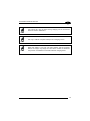
1.4
INSERTING MICROSD CARD
Falcon X3+ provides the possibility to add a microSD memory storage card. To
access the microSD card slot and insert the card, proceed as follows:
1.
Turn off the Falcon X3+.
2.
Press the latch release and lift the battery from the enclosure, as indicated in the
figure below:
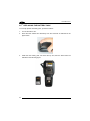
3.
Open the microSD card slot by pulling up the locking plate:
8
INTRODUCTION
1
4.
Insert the microSD card with the written part upward. Lock the card into place by
pushing the cardholder down:
5.
Replace battery.
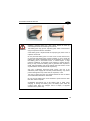
1.4.1
Removing the MicroSD Card
To remove the microSD card, follow the steps above to access the SD area, and
remove it from its slot.
Follow proper ESD precautions to avoid damaging the SD. Proper
ESD precautions include, but are not limited to, working on an ESD
mat and ensuring that the operator is properly grounded.
CAUTION
Do not force the card. If you feel resistance, remove the card, check
the orientation, and reinsert it.
Do not use the microSD card slot for any other accessories.
9
1 FALCON™ X3+
1
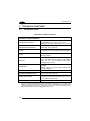
1.5
ACCESSORIES
Cradles
94A150057 Dock, Single Slot, FalconX3
94A151131 Dock, Powered Mobile, FalconX3
94A150056 Dock, Ethernet 4 Slot, FalconX3
94A151135 Charger, 4 Slot Dock, FalconX3
94A151137 Charger, 4 Slot Battery, FalconX3
Batteries
94ACC1386 Battery, High Capacity, FalconX3
Power Supply
94ACC1381 Power Supply, Dock, PWR Plug 2.1mm
94ACC1385 Power Supply, Charger, MBC and Dock
Cables
94A051970 Cable, USB Handylink, Client
94A051971 Cable, USB Handylink, Host
94A051972 Cable, RS232 Handylink, Client
94A051973 Cable, RS232 Handylink, Host
94A051975 Power Adapter, 12 to 24V PWR Plug 2.1mm
94A051976 Adapter, PWR Jack 2.1mm to Handylink
Various
94ACC0104 Rubber Shell, FalconX3+
95ACC1056 Holster, FalconX3
94ACC1371 Module, Ethernet, Single Slot Dock
94ACC1372 Module, Modem, Single Slot Dock
94ACC1388 Softcase, FalconX3
94ACC1390 Handle Kit, Falcon X3+
94ACC1391 Coverplate Kit, FalconX3
94ACC1392 Stylus, FalconX3 Pen with Tether (5pcs)
Use only Datalogic approved power supply and cables. Use of an
alternative power supply will invalidate any approval given to this
device and may be dangerous.
NOTE
10
BATTERIES AND MAINTENANCE
2
2
BATTERIES AND MAINTENANCE
Rechargeable backup batteries and battery packs are not initially
fully charged. Therefore the initial operation to perform is to charge
them. See below.
NOTE
By default, the battery pack is disconnected at the factory to avoid
damage due to excessive draining.
NOTE
Annual replacement of rechargeable battery pack avoids possible
risks or abnormalities and ensures maximum performance.
CAUTION
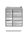
2.1
CHARGING THE BATTERY PACK
The battery pack autonomy varies according to many factors, such
as the frequency of barcode scanning, RF usage, battery life,
storage, environmental conditions, etc.
NOTE
The battery icon on the Taskbar indicates when the battery pack is low.
It is possible to recharge the battery pack by connecting the power supply directly to
the Falcon X3+.
Alternatively, it is also possible to recharge the battery pack by inserting the Falcon
X3+ into the single slot dock or the multi battery charger.
Moreover recharging is possible by USB Direct connection with the host computer,
but with longer charging times and only if the mobile computer off.
During the charging process the LED positioned at the right side of the display is red
constant. Once the charging process has been completed this LED is green
constant.
11
1 FALCON™ X3+
2
The stand-alone battery pack may be recharged outside a Falcon X3+ using the
spare battery charging slot on the back of the single slot dock or the multi battery
charger.
Do not use the Falcon X3+ until batteries are charged for minimum 4
hours.
CAUTION
Risk of explosion if battery is replaced by an incorrect type.
Dispose of used batteries according to the instructions.
CAUTION
Il y a risque d’explosion si la batterie est remplacée par une batterie
de type incorrect.
CAUTION
Mettre au rebut les batteris usagées conformément aux instructions.
Avoid storing batteries for long periods in a state of full charge or very
low charge.
CAUTION
We recommend charging the battery pack every two to three months
to keep its charge at a moderate level to maximize battery life.
Even if the storage temperature range is wider, in order to achieve
the longest battery life, store the terminal and the spare batteries
between -30 to 70 ºC (-22 to 158 ºF).
NOTE
Falcon X3+ should be charged at an ambient temperature between 0
- 35º C (32 to 95 ºF) to achieve the maximum charging rate.
Never charge the main device or spare batteries in a closed space
where excessive heat can build up.
Close to the limits of the working temperature, some display and/or
battery performance degradation may occur.
The battery level may display incorrectly for several minutes after the
Falcon X3+ is disconnected from its charger if the charging cycle is
not completed.
NOTE
12
BATTERIES AND MAINTENANCE
2
The Falcon X3+ may get warm during charging, this is normal and
does not mean a malfunction.
NOTE
Use only a USB-IF compliant USB port as a charging source.
NOTE
NOTE
When the battery is very low, the audio feature and the scanning
feature of imager, long range and XLR laser models are disabled.
They will be re-enabled a few minutes after the charging starts.
13
1 FALCON™ X3+
2
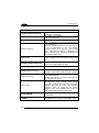
2.2
REPLACING THE BATTERY PACK
To correctly replace the battery pack, proceed as follows.
1.
Turn off the Falcon X3+.
2.
Press the latch release and lift battery from the enclosure as indicated in the
figure below:
3.
Install the new battery pack, first insert the top end, then the latch bottom as
indicated in the following figure:
14
BATTERIES AND MAINTENANCE
2
Installing, charging and/or any other action should be done by
authorized personnel and following this manual.
WARNING
The battery pack may get hot, explode, ignite, and/or cause serious
injury if exposed to abusive conditions.
If the battery pack is replaced with an improper type, there is risk of
explosion and/or fire.
Do not place the battery pack in or near a fire or other heat source;
do not place the battery pack in direct sunlight, or use or store the
battery pack inside unventilated areas in hot weather; do not place
the battery pack in microwave ovens, in clothes dryers, in high
pressure containers, on induction cook surfaces or similar devices.
Doing so may cause the battery pack to generate heat, explode or
ignite. Using the battery pack in this manner may also result in a loss
of performance and a shortened life expectancy.
Use only a Datalogic approved power supply. The use of an
alternative power supply will void the product warranty, may cause
product damage and may cause heat, an explosion, or fire.
The area in which the units are charged should be clear of debris
and combustible materials or chemicals.
Do not use the battery pack of this terminal to power devices other
than this mobile computer.
Immediately discontinue use of the battery pack if, while using,
charging or storing the battery pack, the battery pack emits an
unusual smell, feels hot, changes colour or shape, or appears
abnormal in any other way.
15
1 FALCON™ X3+
2
WARNING
Do not short-circuit the battery pack contacts connecting the positive
terminal and negative terminal. This might happen, for example,
when you carry a spare battery pack in your pocket or purse;
accidental short–circuiting can occur when a metallic object such as
a coin, clip, or pen causes direct connection of the contacts of the
battery pack (these look like metal strips on the battery pack). Short–
circuiting the terminals may damage the battery pack or the
connecting object.
Do not apply voltages to the battery pack contacts.
Do not pierce the battery pack with nails, strike it with a hammer,
step on it or otherwise subject it to strong impacts, pressures, or
shocks.
Do not disassemble or modify (i.e. bend, crush or deform) the battery
pack. The battery pack contains safety and protection devices,
which, if damaged, may cause the battery pack to generate heat,
explode or ignite.
In case of leakage of liquid from the battery, avoid contact with liquid
the skin or eyes. If the contact occurs, immediately wash the affected
area with water and consult a doctor.
Do not solder directly onto the battery pack.
Do not expose the battery pack to liquids.
Avoid any knocks or excessive vibrations. If the device or the battery
is dropped, especially on a hard surface, you should take it to the
nearest Authorised Repair Centre for inspection before continuing to
use it.
Do not replace the battery pack when the device is turned on.
Do not remove or damage the battery pack’s label.
Do not use the battery pack if it is damaged in any part.
Battery pack usage by children should be supervised.
Collect and recycle waste batteries separately from the device in
compliance with European Directive 2006/66/EC, 2011/65,
2002/96/EC and subsequent modifications, with US and China
regulatory laws and regulations about the environment.
16
BATTERIES AND MAINTENANCE
2
In order to maximize operating autonomy, the Falcon X3+ checks
its battery level at all times. If the battery is not sufficiently
charged, the Falcon X3+ will not turn on when the ON/OFF
Power button is pressed.
NOTE
In this case, either substitute a sufficiently charged battery, insert
the Falcon X3+ into a powered cradle, or plug it into a wall
charger.
To maximize battery life, turn off radios when they are not
needed.
NOTE
17
1 FALCON™ X3+
2
2.3
CLEANING THE MOBILE COMPUTER
Periodically clean the Falcon X3+ with a slightly dampened cloth.
Do not use alcohol, corrosive products or solvents.
18
CONNECTIONS
3
3
CONNECTIONS
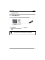
3.1
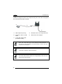
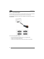
USB CONNECTION
You can use the Datalogic Handylink cable 94A051970 to directly connect the Falcon
X3+ to a host computer to transfer data through the USB interface.
A
C
B
Key:
A
Host computer
B
94A051970 Handylink USB Client
Cable
C
Falcon X3+
Connection through the cable complies to USB 2.0 standard.
NOTE
19
1 FALCON™ X3+
3
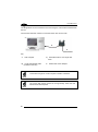
The Single Dock can be connected to the Host using the A to B USB cord included in
the box.
Once the host has been turned on, insert the Falcon X3+ into the dock.
A
C
B
D
Key:
A
Host computer
B)
A to B USB straight cable
(included in the box)
A)
D
94A150057 Falcon X3+ Single Slot
Dock
94ACC1381 Power Adapter
Connection through the cradle complies to USB 2.0 standard.
NOTE
The actual data transfer speed can be appreciably lower than the
maximum theoretical speed.
NOTE
20
CONNECTIONS
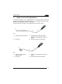
3.2
3
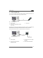
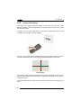
CONNECTION TO USB PERIPHERALS
To connect the Falcon X3+ to a USB keyboard or a memory device, connect the
terminal to the Datalogic 94A051969 cable or to the Datalogic 94A051971 cable
(together with a standard A to micro A USB cable).
For all these devices maximum current withdrawal must be below 100mA.
B
A
C
D
Key:
A
Keyboard with USB interface
C
94A051969 Micro USB Host Cable/
94A051971 Handylink Micro USB Host
Cable
B
Falcon X3+
D
Standard A to Micro A USB Cable
B
A
C
D
Key:
A
USB hard drive/ external
memory source
C
94A051971 Handylink Micro USB Host
Cable
B
Falcon X3+
D
Standard A to Micro A USB Cable
21
1 FALCON™ X3+
3
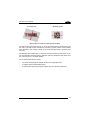
Connect the Single Slot Dock to the peripheral using the A to B USB cord (together
with a standard USB cable if needed).
D
A
C
B
E
A
USB Peripheral (memory)
D
94A150057 Falcon X3+ Single Slot Dock
B
Standard A to Micro A USB
Cable
E
94ACC1381 Power Adapter
C
A to B USB straight cable
(included in the box)
Falcon X3+ works with most of the mentioned USB peripherals. In
any case, we can’t guarantee the interoperability of Falcon X3+ with
all devices on the market.
NOTE
Connection complies to USB 2.0 standard.
NOTE
The actual data transfer speed can be appreciably lower than the
maximum theoretical speed.
NOTE
22
CONNECTIONS
3.3
3
RS232 CONNECTION
You can use the Datalogic 94A051972 cable to directly connect the Falcon X3+ to a
host computer to transfer data through the RS232 interface.
A
C
B
Key:
A
Host computer
B
94A051972 Handylink Micro RS232
Client Cable
C
Falcon X3+
The Single Slot Dock can be connected to the Host by means of a standard null
modem cable such as Datalogic 94A051020 CAB-427 for 9-pin connections.
Once the Host has been turned on, insert the Falcon X3+ into the dock.
A
C
B
D
Key:
A
Host Computer
C
94A150057 Falcon X3+ Single
Slot Dock
B
94A051020 CAB-427 RS232
Null Modem Cable
D
94ACC1381 Power Adapter
23
1 FALCON™ X3+
3
3.4
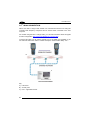
WLAN CONNECTION
Falcon X3+ 802.11 a/b/g/n radio models can communicate with the host using the
on-board radio frequency component and an Access Point connected to the host
computer.
For models using the 802.11 a/b/g/n radio, you can find information about the applet
for radio configuration: http://www.summitdatacom.com/SCU.htm.
To launch this utility you can tap the specific icon if it is visible on the taskbar or you
can select the menu item: Start-> Summit and tap the ‘Summit Client Utility’ icon.
A
A
B
C
Key:
A) Falcon X3+
B) Access point
C) Host – Application Server
24
CONNECTIONS
3
802.11 a/b/g/n radio module is on by default, in order to avoid
wasting energy, you can switch it off using the Wireless
Communications applet.
NOTE
NOTE
Suspending the terminal powers off the 802.11 a/b/g/n radio and
drops the radio connection. When the terminal resumes, depending
on the radio power mode and security protocol selected, it may take
up to 30 seconds for the 802.11 a/b/g/n radio driver to re-associate
the radio to the network.
Area coverage and radio performance may vary, due to
environmental conditions, access point types or interference caused
by other devices (microwave ovens, radio transmitters, etc.).
NOTE
In case of heavy usage the Falcon X3+ may get warm; this is normal
and does not mean a malfunction.
NOTE
25
1 FALCON™ X3+
3
3.5
WPAN CONNECTIONS
Falcon X3+ models with Bluetooth can communicate with other Bluetooth
devices, such as a printer, within a range of 10 m, using the on-board Bluetooth
module.
B
A
Key:
A) Falcon X3+
B) Bluetooth printer
NOTE
In order to extend battery life, the Bluetooth module is off by
default. If you need to have Bluetooth working, the module must be
powered on using the Wireless Manager applet (see par. 4.6.6), and
perform the Discovery procedure (see par. 4.7.2).
NOTE
Suspending the terminal powers off the Bluetooth radio and drops
the piconet (Bluetooth connection). When the terminal resumes, it
takes approximately 10 seconds for the Bluetooth radio driver to reinitialize the radio.
NOTE
26
Area coverage and Bluetooth radio performance may vary, due to
environmental conditions or interference caused by other devices
(microwave ovens, radio transmitters, etc.).
CONNECTIONS
3.6
3
WIRELESS AND RADIO FREQUENCIES WARNINGS
Use only the supplied or an approved replacement antenna.
Unauthorized antennas, modifications or attachments could
damage the product and may violate laws and regulations.
WARNING
Most modern electronic equipment is shielded from RF signals.
However, certain electronic equipment may not be shielded against
the RF signals generated by Falcon X3+.
WARNING
Datalogic recommends persons with pacemakers or other medical
devices to follow the same recommendations provided by Health
Industry Manufacturers Associations for mobile phones.
Persons with pacemakers:
WARNING
•
Should ALWAYS keep this device more than twenty five (25) cm
from their pacemaker and/or any other medical device;
•
Should not carry this device in a breast pocket;
•
Should keep the device at the opposite side of the pacemaker
and/or any other medical device;
•
Should turn this device OFF or move it immediately AWAY if
there is any reason to suspect that interference is taking place.
•
Should ALWAYS read pacemaker or any other medical device
guides or should consult the manufacturer of the medical device
to determine if it is adequately shielded from external RF energy.
In case of doubt concerning the use of wireless devices with an
implanted medical device, contact your doctor.
Turn this device OFF in health care facilities when any regulations
posted in these areas instruct you to do so. Hospitals or health care
facilities may use equipment that could be sensitive to external RF
energy.
WARNING
27
3
1 FALCON™ X3+
WARNING
RF signals may affect improperly installed or inadequately shielded
electronic systems in motor vehicles. Check with the manufacturer
or its representative regarding your vehicle. You should also
consult the manufacturer of any equipment that has been added to
your vehicle.
WARNING
An air bag inflates with great force. DO NOT place objects,
including either installed or portable wireless equipment, in the area
over the air bag or in the air bag deployment area. If vehicle’s
wireless equipment is improperly installed and the air bag inflates,
serious injury could result.
WARNING
Turn off the device when in any area with a potentially explosive
atmosphere. Observe restrictions and follow closely any laws,
regulations, warnings and best practices on the use of radio
equipment near fuel storage areas or distribution fuel areas,
chemical plants or where some operation involves use of explosive
materials.
Do not store or carry flammable liquids, explosive gases or
materials with the device or its parts or accessories.
Areas with a potentially explosive atmosphere are often, but not
always, clearly marked or showed.
Sparks in such areas could cause an explosion or fire, resulting in
injury or even death.
28
USE AND FUNCTIONING
4
4
USE AND FUNCTIONING
The use of the Falcon X3+ depends on the application software loaded. However
there are several parameters that can be set and utilities that can be used to perform
some basic functions such as data capture, communications, file management, etc
4.1
STARTUP
The Falcon X3+ turns on when the battery pack or the external supply is inserted and
the ON/OFF Power button is pressed.
After the battery pack is installed, use the [ON/OFF] key to turn the mobile computer
on and off.
As soon as the mobile computer is on, the Windows CE 6.0 desktop will appear on
the screen. Wait a few seconds before starting any activity so that the mobile
computer completes its startup procedure.
Desktop
Control Panel
Use the stylus (par. 4.1.1) as suggested to select icons and options.
The mobile computer goes into power-off (low power with display and keyboard
backlight off), when it is not used for more than a programmable timeout, which is
defined in the POWER applet of the Control Panel. In this mode it can be awakened
(resuming operation) by the [ON/OFF] key.
29
1 FALCON™ X3+
4
The mobile computer can also be awakened or suspended
programmatically.
NOTE
4.1.1
Using the Stylus
The stylus selects items and enters information. The stylus functions like a mouse.
Double Tap:
Double tap the screen with the stylus to open items and select
options.
Drag:
Hold the stylus on the screen and drag across the screen to
select text and images. Drag in a list to select multiple items.
Tap-and-hold:
Tap and hold the stylus on an item to see a list of actions
available for that item. On the pop-up menu that appears, tap the
action you want to perform.
To recalibrate the touch screen use the Stylus Applet (see par. 4.6.7).
Use only original Datalogic styluses supplied with the product itself.
In harsh applications, use of screen protectors should be taken into
consideration, in order to extend the touch screen operating life.
CAUTION
To prevent damage to the screen, do not use sharp objects or any
tool other than the Datalogic provided stylus.
Do not apply not necessary high pressures on the screen.
For applications where an intensive use of the touch screen is
foreseen, please consider that touch screen components are subject
to progressive wear.
30
USE AND FUNCTIONING
4.1.2
4
Touch Gestures
Touch gestures describe gestures in which you use a finger or stylus to make a
short, directional movement over a control or object on the screen. Most gestures are
a single stroke. Windows CE supports five kinds of gestures.
Tap:
A tap represents the left click of a mouse.
Double Tap:
A double tap represents the left double click of a mouse.
Hold:
The user can press and hold on the screen to represent the right
click of a mouse.
Flick:
The user can move a finger across the screen to initiate per-pixel
scrolling, and if this movement is fast enough, scrolling will
continue after the finger is lifted.
Pan:
The user can press and hold on the screen and then drag the
finger in any direction to represent a mouse move event.
31
1 FALCON™ X3+
4
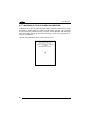
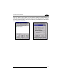
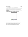
4.2
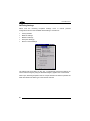
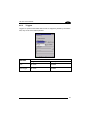
WINDOWS CE TOUCH SCREEN CALIBRATION
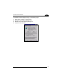
In Windows CE, at the very first Falcon X3+ startup, following a clean boot to restore
the registry to default values, the mobile computer startup (see par. 4.1) is preceded
by the touch screen calibration screen. The touch screen calibration will also appear
when the mobile computer is hard reset (cold boot), but the user may press Esc to
exit from the calibration.
The user must calibrate the touch screen (see par. 4.6.7)
Touch Screen Calibration Screen
32
USE AND FUNCTIONING
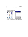
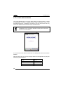
4.3
4
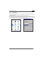
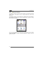
DATA CAPTURE
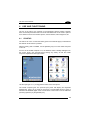
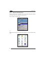
To capture data tap Start > Settings > Control Panel > double tap Decoding:
To configure and enable data capture parameters refer to par. 4.6.1.
33
1 FALCON™ X3+
4
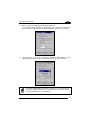
4.3.1
Laser Data Capture
To scan barcodes, point the Falcon X3+ laser model onto the code from a distance
within the reading range while pressing the SCAN key or the pistol trigger.
The lighted band emitted by the laser must completely cross the barcode as shown in
the figure below.
If the scan has taken place correctly:
−
−
−
34
the Good Read LED glows steadily Green for a configurable time;
if enabled, the Good Read Beep plays;
if enabled, the GreenSpot projects a green spot onto the bar code image.
USE AND FUNCTIONING
4
Remove the protective film cover over the Laser Output Window
before use.
NOTE
35
1 FALCON™ X3+
4
4.3.2
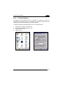
Imager Data Capture
The Falcon X3+ Imager captures a picture of the entire bar code. The omnidirectional scanning does not require that the operator orient the bar code to align
with the scan pattern.
To read a 1D or 2D code, simply point the Falcon X3+ Imager model onto the code
and press the SCAN Key or the pistol trigger.
The Falcon X3+ Imager uses an intelligent aiming system pattern, similar to those on
cameras, indicating the field of view, which should be positioned over the code:
Aiming System
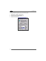
If the aiming system pattern is centered over the entire symbology as shown in the
following figure, either wait for the timeout or release the Scan key or the trigger to
capture the image.
A red beam illuminates the code, which is captured and decoded. You will get a good
read.
36
USE AND FUNCTIONING
Linear barcode
4
2D Matrix symbol
ÌBX3ÉÎ
Relative Size and Location of Aiming System Pattern
The field of view changes its size as you move the reader closer or farther away from
the code. The field of view indicated by the aiming system pattern will be smaller
when the Falcon X3+ Imager is closer to the code and larger when it is farther from
the code.
Symbologies with smaller bars or elements (mil size) should be read closer to the
unit. Symbologies with larger bars or elements (mil size) should be read farther from
the unit. (See par. 5.1 for further details).
If the scan has taken place correctly:
−
the Good Read LED glows steadily Green for a configurable time;
−
if enabled, the Good Read Beep plays;
−
If enabled, the Green Spot projects a green spot onto the bar code image.
37
1 FALCON™ X3+
4
4.4
DESCRIPTION OF THE KEYS
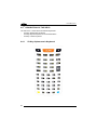
The Falcon X3+ comes with three different keyboards:
A 52-key alphanumeric keyboard
A 52-key keyboard specific for Terminal Emulation
A 29-key numeric keyboard
4.4.1
38
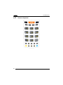
52-Key Alphanumeric Keyboard
USE AND FUNCTIONING
4
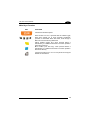
Main Keys Function
KEY
FUNCTION
It starts barcode data capture.
Direct access to F1-F4. If pressed after the Yellow toggle,
these keys enable you to move forwards, backwards,
upwards or downwards within text fields, scroll through a
Menu list or browse among folder files.
Yellow modifier (toggle key): when pressed before a
standard key, it enables the character or function printed in
yellow above the key.
Blue modifier (one shot key): when pressed before a
standard key, it enables the character or function printed in
blue above the key.
It powers the Falcon X3+ on or off. it is placed on the upper
left side of the terminal.
39
1 FALCON™ X3+
4
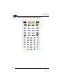
4.4.2
40
52-Key Terminal Emulation 5250 Keyboard
USE AND FUNCTIONING
4
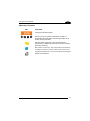
Main Keys Function
KEY
FUNCTION
It starts barcode data capture.
They let you move forwards, backwards, upwards or
downwards within text fields, scroll through a Menu list or
browse among folder files.
Yellow modifier (toggle key): when pressed before a
standard key, it enables the character or function printed in
yellow above the key.
Blue modifier (one shot key): when pressed before a standard key,
it enables the character or function printed in blue above the key.
It powers the Falcon X3+ on or off. it is placed on the upper
left side of the terminal.
41
1 FALCON™ X3+
4
4.4.3
42
Numeric Keyboard
USE AND FUNCTIONING
4
Main Keys Function
KEY
FUNCTION
It starts barcode data capture.
They let you move forwards, backwards, upwards or
downwards within text fields, scroll through a Menu list or
browse among folder files.
Yellow modifier (toggle key): when pressed before a
standard key, it enables the character or function printed
in yellow above the key.
Blue modifier (one shot key): when pressed before a
standard key, it enables the character or function printed
in blue above the key.
It powers the Falcon X3+ ON or OFF. It is placed on the
upper left side of the terminal.
43
1 FALCON™ X3+
4
4.4.4
Resetting the Falcon X3+
There are several reset methods for the Falcon X3+.
A warm boot terminates an unresponsive application and clears the working RAM,
but preserves the file system. Registry is restored from persistent memory if available
or returned to factory default.
A cold boot forces all applications to close reinitializing completely the system. It
clears the working RAM, but the file system is preserved. Registry is restored from
persistent memory.
A clean boot restores the Falcon X3+ to a clean configuration: both the registry and
the file system returns to a clean status that conforms to factory default.
Warm Boot
To perform a warm boot, press and hold the following keys simultaneously:
+
+
Cold Boot
To perform a cold boot, do the following steps:
1.
2.
3.
4.
5.
Turn off the Falcon X3+ by pressing the on-off key.
Pull the battery latch down and remove the battery pack.
Press and hold the scan button and then press the reset button.
Insert the battery pack.
Turn on the Falcon X3+ by pressing the on-off key.
Clean Boot
To perform a clean boot, do the following steps:
1.
2.
Perform a Cold Boot (see Cold Boot)
Press and hold down the 0 and Esc keys simultaneously and then press the onoff key:
+
3.
44
A dialog box will appear asking for confirmation. Press the Enter Key.
USE AND FUNCTIONING
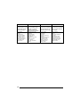
Registry
File System
Warm Boot
Restored
from flash
Preserved
4
Cold Boot
Restored from
flash
Preserved
Clean Boot
Clean configuration (no user config)
Clean Installation (no user files)
45
1 FALCON™ X3+
4
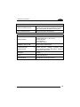
4.5
STATUS INDICATORS
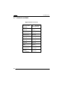
4.5.1
LED Status
The Falcon X3+ provides three different LEDs signaling the mobile computer status.
LED
Charging Status
(left side)
Keyboard Status
(center)
Good Read
(right side)
STATUS
Green
It is solid once the charging process has
been completed (full charge).
Red
It is solid while charging.
Red blinking
It blinks in case of charge fault.
Off
Keyboard in primary.
Yellow solid
Yellow alternate key mode.
Blue solid
Blue alternate key mode
Pink
CapsLock enabled.
Red
Green
46
Scanning LED is ON from the time the
user hits the scan button (Trigger) until
the bar code is decoded (laser models)
Time-out (imager models).
Scanning LED is ON, showing a good
decode.
USE AND FUNCTIONING
4.5.2
4
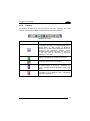
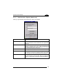
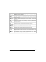
Taskbar
The Taskbar provides quick view and links to the Wi-Fi, Bluetooth, and Clock
settings. It also makes available the keyboard SIP and window selection.
Windows CE Taskbar
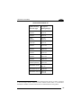
ICONS
DESCRIPTION
ActiveSync connection icon is displayed when
connected to ActiveSync or Windows Mobile Device
Center either by USB, RS232, or Bluetooth.
Double-tap it to open a status dialog that will let you
disconnect the ActiveSync session without
physically disconnecting the device from the PC. It
is the only way to disconnect a Bluetooth
ActiveSync connection.
Battery icon displays the system battery status.
It indicates that the battery is charging.
Bluetooth Manager icon displays whether Bluetooth
is enabled, paired, or turned off. Double-tap this
icon to open the Bluetooth Manager control panel
applet.
Network connectoid icon displays whether you are
connected or not to Ethernet, Wi-Fi, or Bluetooth
Personal Area Network.
47
1 FALCON™ X3+
4
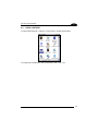
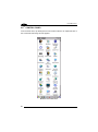
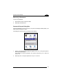
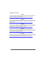
4.6
CONTROL PANEL
From the Start menu, tap Settings then Control Panel. Below is an expanded view of
the Control Panel showing all of the applets.
Windows CE Control Panel
48
USE AND FUNCTIONING
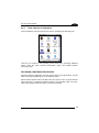
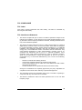
4.6.1
4
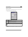
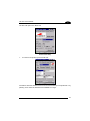
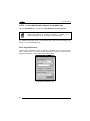
Data Capture Configuration
From the Windows CE control panel main window, double tap the Decoding icon:
There are two sections in the Decoding control panel, each containing additional
pages. There are seven General Configuration pages and multiple Barcode
symbology pages.
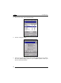
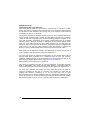
DECODING CONFIGURATION PAGES
Select the desired configuration from the options shown in the figure below, and the
other Decoding Properties figures on the following pages.
Select General,1D Bar Code or 2D Bar Code, then use the menu or tap the left and
right arrow keys to navigate the different pages of the Decoding utility. The menu
options will change to reflect the items most recently selected.
49
4
1 FALCON™ X3+
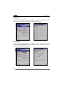
Notification
From the Decoding Properties page, tap Configure > General > Notification. Use it to
set volume, tone, duration, and number of various types of beeps.
Good Read
From the Decoding Properties page, tap Configure > General > Good Read. Use it to
enable Good Read indications, the use of Green Spot, the LED and a to set the
decoding timeout for decoding labels.
50
USE AND FUNCTIONING
4
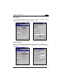
Formatting
From the Decoding Properties page, tap Configure > General > Formatting. Use it to
configure prefix, suffix and data separator character strings.
General Options
From the Decoding Properties page, tap Configure > General > General Options.
Select from Label Programming Enable, Symbology IDs and Group Separator
Replacement.
51
4
1 FALCON™ X3+
Decoding Options
From the Decoding Properties page, tap Configure > General > Decoding Options.
Use it to configure the User ID for symbologies, Redundancy and Aggressive
Decoding (if supported by the decoding module). Select a symbology to view or
change the available properties settings.
52
USE AND FUNCTIONING
4
Spot Beam
From the Decoding Properties page, tap Configure > General > Spot Beam. It allows
enabling and configuration of Spot Beam and triggering modes.
It is only available on devices equipped with laser and advanced long range laser
decoding modules that support the Spot Beam Feature.
53
4
1 FALCON™ X3+
Scanning Options
From the Decoding Properties page, tap Configure > General > Scanning Options. It
configures the scan width and allows to enable the automatic range detection.
Devices
From the Decoding Properties page, tap Configure > General > Devices. Use it to
enable or disable the keyboard wedge for Barcode scanner.
54
USE AND FUNCTIONING
4
1D Barcode Symbology Pages
Use the drop-down menus from Configure > 1D Barcode, or tap the left and right
arrow keys to navigate the different pages of the barcode symbology pages.
Select Configure > 1D Bar Code from the menu to view other configuration options.
Each barcode symbology opens to its own page, as shown in the figure below. Refer
to the sample symbology control panels for examples of the types of fields and
options you can modify.
55
4
1 FALCON™ X3+
Decoding Settings
Select from the Decoding Properties Settings menu to restore previous
configurations and/or other available default settings. Choose from:
•
Factory Defaults
•
Minimum Settings
•
Maximum Settings
•
Save (New Settings)
•
Revert to Saved Settings
The settings are saved when you tap ‘Yes’. To permanently save these settings you
need to save the Registry using the Persistent Registry applet in the Control Panel.
When open, Decoding Properties acts as a simple barcode test tool that provides the
Data decoded and the Data Type of the barcode scanned.
56
USE AND FUNCTIONING
4.6.2
4
DL Buttons
You can use DL Buttons Tab to associate specific keys, such as <F1>-<F10>, with
specific applications.
From the control panel main window, double tap the DL Buttons icon.
On the DL Buttons tab, customize the program hardware buttons to launch your most
used applications. Under ‘Select a button’, select the button you want to assign a
function to, and then select a program from ‘Assign a function’.
57
1 FALCON™ X3+
4
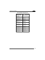
COMMAND
DESCRIPTION
Select a Button
This pull-down list displays the available function keys
to define. Select the desired one from the list.
New
Select/tap to specify a new Button, not on the “Select a
Button”list.
Delete
Tap to delete the selected Button. You can only delete
the Buttons you have added. You cannot delete the
following buttons: “Alt + 6”, “Left Button”, “Pistol
Trigger”, “Right Button”, “Scan”
Assign a function
This pull-down list displays the available functions.
Application
Displays path to the selected application.
Browse
to browse for application files. You can
Select/tap
associate an executable program with the specified
Button
Arguments
Type the command-line arguments that are needed for
the specified application. This option is only available
when “Launch Application” is selected in the “Assign a
function” pull-down list.
58
USE AND FUNCTIONING
4
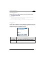
Adding a new Button
When you select “New” on the “DL Buttons” tab, this opens the “Add Key” dialog box.
To define a new Button, complete the following steps:
1.
Enter the key combination in the “Add Key” textbox.
COMMAND DESCRIPTION
Enter Key
Enter the desired key combination in this text box to define a Button.
OK
Select/tap OK to add the specified Button.
X
Select/tap X to cancel the specified Button.
Make sure you do not attempt to add a Button that is already defined.
NOTE
2.
Select/tap OK to save the new Button. If you select/tap “X”, the key will not be
saved.
59
4
1 FALCON™ X3+
It is possible for the keyboard wedge to activate assigned Buttons
using alphanumeric characters. Barcodes containing characters
associated with assigned Buttons will trigger the action or
application assigned to that Button.
CAUTION
60
USE AND FUNCTIONING
4.6.3
4
Triggers
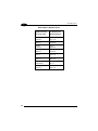
Triggers are special customizable buttons that are mapped by default by DL Buttons.
Also, they can be set as wakeup buttons:
TRIGGERS
DEFAULT CONFIGURATION
Assigned Function
Wake-up
Scan
Bar Code
Disabled
Pistol Trigger
Bar Code
Enabled
61
1 FALCON™ X3+
4
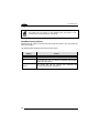
4.6.4
Application Switcher
The application switcher provides the same functionality as the standard Windows®
Alt+Tab function. This allows the user to switch between the various open
applications.
The application switcher can be activated via an assigned shortcut key specified in
the DL Buttons tab (see par. 4.6.2.) When the assigned button is pressed, the dialog
shown below will be displayed:
Press the assigned button to cycle through the running applications when the dialog
is open. Press <Enter> to switch to the selected application or <Esc> to close the
application switcher.
62
USE AND FUNCTIONING
4.6.5
4
Persistent Registry
The Registry stores information that are necessary to configure the system for
applications and hardware devices. The Registry also contains information that the
operating system continually references to during operation.
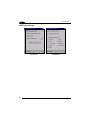
To persist the Registry settings between boots, do the following steps:
1.
2.
3.
4.
Select Start > Settings > Control Panel.
Double-tap the “Persistent Registry” icon.
Tap the “Persist” button.
Tap OK to exit.
63
4
To change Persistent Registry timing, do the following steps:
1.
2.
3.
4.
64
Select Start > Settings > Control Panel.
Double-tap the “Persistent Registry” icon.
Select a time interval from the menu.
Tap OK to save and exit.
1 FALCON™ X3+
USE AND FUNCTIONING
4
To deselect Persistent Registry timing, do the following steps:
1.
2.
3.
4.
Select Start > Settings > Control Panel.
Double-tap the ‘Persistent Registry’ icon.
Deselect the ‘Persist Registry settings’ box.
Tap OK to save and exit.
65
1 FALCON™ X3+
4
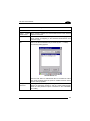
4.6.6
Wireless Communications
Wireless networking has a customized control, Summit Client Utility (SCU), specific
to the radio. There are two methods to access the SCU.
Start > Programs > Summit > SCU:
Or
From the Control Panel main window, double tap Wi-Fi to open the Summit Client
Utility:
66
USE AND FUNCTIONING
4
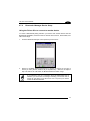
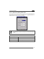
The SCU will open to the “Main” tab:
Summit Client Utility
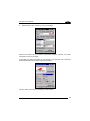
1.
To create a new profile, tap the "Profile" tab:
Information about the wireless network can be entered directly in the profile tab or by
pressing “Scan” when the desired network ESSID is in range.
67
4
1 FALCON™ X3+
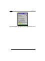
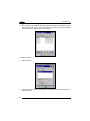
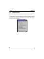
2.
At the "Scan" screen, select the desired SSID:
3.
Click the "Configure" button
4.
Follow the on-screen instructions to setup security parameters for your network.
For more detailed settings specific to your installation please contact your
wireless network administrator.
68
USE AND FUNCTIONING
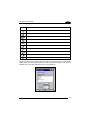
5.
4
When finished, click “Commit” to save your settings.
Return to the “Main” tab, if you have not previously selected “Commit” you will be
prompted to save your changes.
At the “Main” tab select the profile you just created. If you used the “scan” button the
desired profile will have the same name as the ESSID.
Use the “Status” tab to check connectivity to the network.
69
4
1 FALCON™ X3+
More detailed information about the applet for radio configuration can be found at
http://www.summitdata.com/SCU.htm.
70
USE AND FUNCTIONING
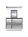
4.6.7
4
Stylus Calibration
You might need to recalibrate the touch screen (i.e. when you attempt to select one
item with the stylus, another item is erroneously selected).
To recalibrate the touch screen, complete the following steps:
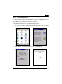
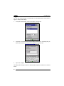
1.
From the Control Panel main window, double tap Stylus to open the Stylus
Settings dialog:
2.
Tap ‘Calibration’ to open the Calibration screen. Tap ‘Recalibrate’:
71
4
3.
4.
5.
1 FALCON™ X3+
Carefully press and briefly hold stylus on the center of the target. Repeat as the
target moves around the screen.
By completing the calibration procedure you implicitly accept the new calibration
settings.
New calibration settings are persistently saved in the Registry.
Startup Stylus Calibration
When starting the terminal, a Welcome Wizard (with Stylus Calibration) comes up if
valid calibration settings are not available. This happens in the following
circumstances:
1.
2.
3.
72
At the first startup of the terminal.
After any cold boot if the user skipped stylus calibration earlier.
After a Clean Boot.
USE AND FUNCTIONING
4.6.8
4
Audio Settings
There are two applets that control volume: Audio and Volume & Sounds.
Audio
From the control panel main window, select the Audio applet by double tapping the
‘Audio’ icon:
The audio control panel can be used to independently set the playback or recording
volume for different types of audio inputs and outputs, such as a headset, powered
mobile dock, or the internal speakers and microphone.
Audio Windows
73
1 FALCON™ X3+
4
Volume & Sounds
From the control panel main window, select the Volume & Sounds applet by double
tapping the Volume & Sounds icon:
The Volume & Sounds applet configures audio features of all speakers and
headphones and appears as follows:
Volume & Sounds Window
74
USE AND FUNCTIONING
4.7
4
CONNECTING TO OTHER COMPUTERS
There is more than one way to connect the Falcon X3+ to a host PC running
Windows. Each requires specific connections in order to function properly.
4.7.1
Windows Mobile® Device Center
The desktop application Windows Mobile® Device Center gives you the ability to
synchronize information between a desktop computer and your Falcon X3+.
Synchronization compares the data on the Falcon X3+ with that on the desktop
computer and updates both with the most recent information.
Windows Mobile® Device Center can be downloaded from Microsoft website
www.microsoft.com. It is only compatible with Windows Vista and Windows 7; if you
run Windows XP or earlier, you have to download Microsoft ActiveSync.
.
You can establish a connection to your Falcon X3+ through the following interfaces:
−
USB either directly or through the Single Dock
−
RS232 either directly or through the Single Dock
−
Bluetooth® (see par. 4.7.2)
To establish a partnership between the Falcon X3+ and a host PC, start Windows
Mobile® Device Center and follow the steps below:
1.
2.
3.
4.
5.
Connect the Falcon X3+ to the host PC. Windows Mobile® Device Center
configures itself and then opens.
On the license agreement screen, click Accept.
On the Windows Mobile Device Center’s Home screen, click Set up your
device.
Select the information types that you want to synchronize, then click Next.
Enter a device name and click Set Up.
When you finish the setup wizard, Windows Mobile Device Center synchronises the
PDA automatically. Microsoft® Office Outlook® emails and other information will
appear on your device after synchronization.
75
4
NOTE
76
1 FALCON™ X3+
The Falcon X3+ running Windows CE does not come equipped with
Microsoft Office Outlook or any other application that allows users to
view contact, calendar, e-mail, or task data. Users can view files
copied to the Falcon X3+ by WMDC's file synchronization feature.
USE AND FUNCTIONING
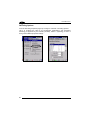
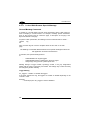
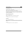
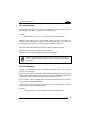
4.7.2
4
Bluetooth® Manager Device Setup
Using the Falcon X3+ to connect to another device
To create a Bluetooth® pairing between your device and another device that has
Bluetooth® capabilities, ensure that the two devices are turned on, discoverable, and
within close range.
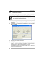
1.
From the Bluetooth Manager control panel tap ‘Connections’.
2.
Search for available Bluetooth® devices by tapping the button for the type of
device you want (Printer, Serial or All) or tap Discovery > Discover to skip this
step. The Falcon X3+ will search for Bluetooth® devices within range.
NOTE
If you attempt to set up a connection when the Bluetooth® radio is
disabled, you will receive a message reminding you that the radio is
turned off, and asking if you want to turn it on. Tap Yes if you need to
enable the Bluetooth® radio.
77
4
3.
1 FALCON™ X3+
Once searching is complete, Bluetooth® device Profiles will be displayed in the
Discovery tab. You can set up a connection to a device in the list by selecting
the device and then tapping the 'Connect' button:
To create a pairing:
1.
Select a service:
2.
Configure any encryption, authentication, or virtual port options required by the
service selected.
78
USE AND FUNCTIONING
Icon
4
Service
Dialup Networking
Printer
Object Push (OPP) Object Exchange (OBEX)
ActiveSync
Human Interface Device (HID) - Keyboard
Serial
Personal Area Network (PAN)
Modem
Headset
Handsfree
Virtual Port allows you to specify the incoming port, which is used to communicate
serially with an incoming device just as if it were a physical COM port. This option is
available only if you have selected a Printer or Serial service.
79
4
1 FALCON™ X3+
You can also select Encrypt or Authenticate from the Bluetooth® control panel to
apply or modify those settings.
1.
To require Authentication, check the checkbox, then tap OK.
2.
If required, the Authentication Request dialog will then open, requesting that you
enter a PIN. Use the Input Panel or the keyboard to type the PIN.
3.
Tap OK to complete.
The dialog will also appear when an Authentication request is received from another
device.
80
USE AND FUNCTIONING
4
Once you have set up a pairing, you can view the settings by double-tapping its
name from the Connections tab. Tap the arrow to change the Virtual Port, or Delete
to remove the device pairing. Tap Sync to initiate a Sync (available only if the service
is an ActiveSync connection).
81
4
1 FALCON™ X3+
Using your device to connect to the Falcon X3+
Before turning on Bluetooth®, ensure that the two devices are within close range and
that both Bluetooth-enabled devices are discoverable.
1.
From the control panel main window, double tap the Bluetooth Manager icon to
open the Bluetooth Manager control panel.
2.
Tap Settings. The Settings tab allows you to enable or disable the Bluetooth®
radio and specify settings for Incoming Connections.
82
USE AND FUNCTIONING
4
3.
Select or clear the “Enable Bluetooth Radio” check box.
If you’re going to be attaching a serial device (i.e. a scanner) to the Falcon
X3, use the Port control to select a virtual COM port to use for the connection.
5.
Tap ‘Find Me’ if you want to make the FalconX3 discoverable to other
Bluetooth® devices for 60 seconds, allowing them to set up a connection.
By default, Bluetooth® is turned off. If you turn it on, and then turn off
your device, Bluetooth® also turns off. When you turn on your device
again, Bluetooth® turns on automatically.
NOTE
83
1 FALCON™ X3+
4
4.8
DATALOGIC FIRMWARE UTILITY
The Datalogic devices are equipped with a field upgradeable firmware mechanism.
Firmware updates are available on the Datalogic website:
http://www.datalogic.com/eng/support-services/automatic-datacapture/downloads/software-utilities-sw-2.html.
After you have downloaded the desired update, there are several ways you can
update the firmware on your device.
−
Use Wavelink Avalanche™ if you have multiple Datalogic devices to update.
For more information refer to the dedicated section of the Wavelink website:
http://www.wavelink.com/Datalogic-device-downloads.
−
If Wavelink Avalanche™ is not available or you have only a few Datalogic
devices to update, use the Datalogic Firmware Utility (DFU), described below,
to install or update the firmware using an ActiveSync connection.
The following sections provide procedures for the retrieval and installation of the
most current firmware image onto a Datalogic device.
4.8.1
Retrieving a Firmware Image Update
The following instructions use Internet Explorer to retrieve the most current firmware
image.
1.
Launch Internet Explorer on your PC and navigate to the Datalogic website.
2.
Navigate to the Downloads section of the website.
3.
Using the device selection fields, select the file you want to download, then
click Save to begin copying the files to your local machine (or local network
location).
84
USE AND FUNCTIONING
4.8.2
4
Installing DFU on the Host PC
The Datalogic Firmware Utility (DFU) provides administrators with a field upgrade
mechanism. You must have Microsoft® ActiveSync (for Windows XP devices) or
Windows Mobile® Device Center (for Windows 7 and Vista devices) already loaded
and running on the host PC to use DFU. Refer to par. 4.7.1 for more information
about Windows Mobile® Device Center.
Prior to installing, you must remove any previous versions of DFU
installed on the host PC.
NOTE
To install the Datalogic Firmware Utility, complete the following steps on the PC:
1.
Go to the Datalogic website and download the most current version of the
Datalogic Firmware Utility. Unzip the file, then double-click to run DFU_Setup.
exe.
2.
Click OK to continue once you have removed previous versions of DFU.
3.
The Welcome to DFU Setup Program screen opens.
4.
−
Please exit all Windows applications before running this installer.
−
Click Next to continue the Setup.
Follow the onscreen instructions to complete the installation.
85
1 FALCON™ X3+
4
4.8.3
Updating the Firmware
After copying the firmware image to the host PC (see par. 4.10.1) and installing DFU
(see par. 4.8.2), you can upgrade the firmware on your Datalogic device.
The following steps require that you have already established an
ActiveSync or Windows Mobile Device Center connection between
the host computer and the Datalogic device
NOTE
1.
Go to Start > Programs > Datalogic > DFU > Datalogic Firmware Utility.
2.
Verify that ActiveSync is selected by clicking Communications > WMDC/
ActiveSync.
Click browse (...) and navigate to the location where you saved the firmware
file for your terminal.
3.
4.
Select the current *.out file and click Open.
5.
Click Update.
6.
DFU will compare the selected firmware image with the firmware already
loaded on the device; if the image is compatible with the connected device,
DFU will proceed to update the firmware image on your device.
After the firmware of your device has been updated, DFU will automatically
perform a warm reset of the device.
86
USE AND FUNCTIONING
4.9
4
DATALOGIC CONFIGURATION UTILITY
Datalogic Configuration Utility (DCU) is a Datalogic Windows-based utility tool
allowing the uploading, modifying and downloading of the configuration of a Datalogic
device. Configuration settings include Scanner, Control Panel, and Datalogic
Desktop Utility (DDU). The DCU installer is downloadable from the Datalogic website
(http://www.datalogic.com/eng/support-services/automatic-datacapture/downloads/software-utilities-sw-2.html).
DCU functions in both direct (with an ActiveSync connection) and indirect (with
Wavelink Avalanche™) modes.
In direct mode, connect a device through ActiveSync and then click on the Get from
Device icon to receive the device’s current configuration.
Once loaded, the Configuration Tree (on the left side of the window) is used to
navigate the device’s configuration. The right side of the window is a work area
where the values of different parameters may be set for each branch of the
configuration tree. Click on the parameter group branch to open it and inspect the
parameters you wish to modify.
After altering the device’s configuration, the new configuration can be sent to the
terminal by clicking on the Send to Device icon.
Reference the Wavelink Avalanche™ documentation on the Wavelink website
(www.wavelink.com/Datalogic-device-downloads) for a description of indirect mode
for DCU, which will allow you to update the configuration of multiple devices
simultaneously over Wi-Fi.
87
1 FALCON™ X3+
4
4.10 DATALOGIC DESKTOP UTILITY
®
Datalogic Desktop Utility (DDU) allows administrators to configure Windows CE and
Embedded Handheld devices to control individual user access. This includes the
ability to:
•
•
•
•
•
Prevent users from changing your device OS settings.
Use Application Selector to replace the desktop with a selection of authorized
applications.
Restrict user access in Internet Explorer.
Set up configuration and customized error recovery mechanisms.
Create quick access hot keys and configure trigger actions.
To open DDU for the first time, tap Start > Settings > Control Panel > or Start >
Programs > Device tools > and then double tap the icon for “Datalogic Desktop
Utility”.
You can also open DDU by pressing the appropriate key shortcut. The default is “Alt
+ 6”
The key combination can be changed by using DL Buttons to redefine
the association for specific keys (such as <F1>-<F10>). See par. 4.6.2
for more information.
NOTE
88
USE AND FUNCTIONING
4.10.1
4
Administrative Options (Admin tab)
When you open the DDU control panel, the “Admin” tab appears.
COMMAND
DESCRIPTION
Enable Datalogic Desktop
Select/tap this checkbox to activate the DDU functions
such as Windows Access Restrictions and Application
Selector.
Enter Password
Enter a password in the text box. This allows the user to
specify a password when this utility is launched. By
default the password is “1234”. A password can consist
of all standard keyboard characters.
Re-Enter Password
Carefully re-enter the password in the second text box.
Set Password
Select/tap “Set Password” to enable the password.
To change or remove the password, enter a new value,
re-enter the new value, and select/tap “Set Password”.
Set Defaults
Select/tap “Set Defaults” to reset the default values of
all the functions on all the tabs. After you select this
option, you will receive a prompt to verify this selection.
89
1 FALCON™ X3+
4
Setting a Password
To set a password:
1.
Enter a password in the field. This allows the user to specify a password when
this utility is launched. By default the password is “1234”.
Be sure to record the Password for future reference.
NOTE
2.
3.
4.
Re-enter the password in the second field.
Select/tap “Set Password” to enable the password.
Select/tap “OK” to close the “Set Password Confirmation” dialog.
NOTE
You must select/tap “Set Password” prior to exiting DDU in order to
store and activate your new password. It is not necessary to select
“Enable Datalogic Desktop”.
If you select/tap “Set Defaults” it will remove all custom settings and
restore all the factory default settings, except a previously set
password.
CAUTION
Changing a Password
To change to a new password:
1.
2.
3.
90
Enter a new value in the “Enter Password field”.
Re-enter the new value in the “Re-enter Password” field.
Select/tap “Set Password”.
USE AND FUNCTIONING
4
Removing a Password
To remove a password:
1.
2.
Enter blanks in both “Password” fields.
Select/tap “Set Password”.
Password Request Dialog Box
Once the password is set, the next time you open the “Datalogic Desktop Utility”, the
DDU Password dialog box opens.
This dialog box will only open if a password was defined.
1.
Type in your password using either the keypad on the unit, or using the stylus on
the soft input panel (SIP).
If you enter an incorrect password, the system will prompt you to input the
correct one.
2.
Select/tap “OK” to verify the password. Or tap “X” to cancel.
91
1 FALCON™ X3+
4
4.10.2
Locked Web Browser Options (LockedWeb tab)
Tap the LockedWeb tab to access the Locked Web Browser Configuration.
Locked Web Browser is disabled by default. To enable, go to
“Advanced settings” on the next page for more information.
NOTE
For additional information about Locked Web Browser commands and metatags, see
section 4.12, Locked Web Browser.
Error Page Redirection
Use the Error Redirection option to provide customized recovery from common
errors. When an error occurs, the browser can redirect access to a specified error
page with instructions on how to recover from the problem.
Locked Web Configuration Tab
92
USE AND FUNCTIONING
4
Error Redirection options
Error Type
The “Error Type” pull-down list displays available Error Types:
(400) Invalid Syntax, (403) Request Forbidden, (404) Object Not
Found, (406) No Response Format, (410) Page Doesn't Exist, (500)
Internal Server Error, (501) Server Can't Do That, Generic Error,
Network Disconnected
Error Page
Edit this textbox to associate a website or html file with the specified
error.
Other options
Full Screen
Set the web browser in full screen mode.
Status Icon
Enable or disable the status icons view (see par. 4.10.3). The status
icons can be configured on the Status tab of DDU.
Trap Keys
When checked:
− all key presses will be trapped by the Locked Web Browser to
prevent the user from accessing unsafe parts of the system. For
example, pressing Ctrl+O to Open a File will not work;
− safe key presses (e.g. Alpha numeric) will still get processed by the
Locked Web Browser as normal. For example entering a number in
a text field on a web page;
− DL Buttons keys will not work in the LockedWeb Browser;
− all Locked Web Browser command keys will work (e.g. Ctrl+0 to
exit).
− When unchecked:
− all keys will be processed normally by the system and the browser;
− DL Buttons keys will work normally;
− all Locked Web Browser command keys will work (e.g. Ctrl+0 to
exit).
Exit
Password
When checked, a password will be required before the Locked Web
Browser can exit. This password is different than the DDU exit
password, with a default value of “0000”, and can be changed in the
“Advanced” settings.
Browser
Home Page
This sets the Internet Explorer home page, regardless of the enable
state of the Locked Web Browser.
Advanced
Pressing this button will launch a dialog used to enable Locked Web
Browser and to configure Advanced settings.
93
1 FALCON™ X3+
4
Advanced Settings
General Tab
94
Context Menu
USE AND FUNCTIONING
4
Advanced Locked Web Browser options
General
Enable Locked When checked, enables the Locked Web Browser when Internet
Web Browser
Explorer is launched.
Disable Cache
Prevents the browser from loading the local intranet page from
cache instead of navigating to the “Network Disconnected” error
redirection page.
Allowed Website Enables a “white list,” which restricts browsing only to files and
URLs in the Allowed Website list (accessed by the “…” button).
List
The following dialog appears:
Allowed Website List
Click the “Add” button to add allowed URLs to the white list. Other
sites will be restricted when the option is enabled. Domain names
must be exactly specified.
Change Exit
Password
Pressing this button brings up a dialog which allows the user to
change the password required to exit the Locked Web Browser
(when the “Exit password” option is selected on the LockedWeb
tab in DDU).
95
4
1 FALCON™ X3+
Context Menu
Enable Context
Menu
Enables the context menu accessed by a touch screen press in
the Locked Web Browser.
Refresh
Adds a “Refresh” item to the Locked Web Browser context menu.
Selecting the “Refresh” item refreshes the web page.
Stop
Adds a “Stop” item to the Locked Web Browser context menu.
Selecting during navigation stops the downloading of a page.
Current URL
Adds a “Current URL” item to the Locked Web Browser context
menu. Selecting the item pops up a dialog displaying the URL for
the current web page.
About
Adds an “About” item to the Locked Web Browser context menu.
Selecting the “About” item pops up the “About” dialog.
Zoom
(WEHH only) Adds a “Zoom” item to the Locked Web Browser
context menu. Selecting the item brings up the IE Zoom Tool.
Back
Adds a “Back” item to the Locked Web Browser context menu.
Selecting the “Back” item performs a navigation to the previous
page.
Home
Adds a “Home” item to the Locked Web Browser context menu.
Selecting the “Home” item navigates to the IE home page.
Minimize
Adds a “Minimize” item to the Locked Web Browser context menu.
Selecting the item minimizes the Locked Web Browser and allows
access to other programs.
Show SIP
Adds a “Show SIP” item to the Locked Web Browser context
menu. Selecting the “Show SIP” item toggles the show state of
the SIP.
Exit
Adds an “Exit” item to the Locked Web Browser context menu.
Selecting the item exits the Locked Web Browser with an optional
password (set in the Locked Web Browser Advanced options).
96
USE AND FUNCTIONING
4.10.3
4
Status Icons Options (Status Tab)
Tap the “Status” tab to access the Status Icons option. You can configure the view of
some status icons that are used in “LockedWeb” and in “Application Selector” to
display the status of: Wi-Fi radio, battery and GSM.
The GSM status icon feature is available only on devices that support
GSM.
NOTE
Status Icons Options
Set Status Icon Defaults
Restores the status icons’ factory settings.
Icon Size
Sets the status icons’ size.
Icon Location
Selects the preferred location for each status icon.
97
1 FALCON™ X3+
4
4.10.4
Windows Controls
Select/tap the “Win” (Windows Controls) tab to access the Windows Controls option.
Use Windows controls to allow or restrict access to Windows system functions.
You can disable normal Windows functions such as the taskbar, leaving nothing but
a blank workspace. This allows applications to be run in full screen mode and
prevents users from accidental or unauthorized use of the taskbar, Internet Explorer,
and any other resident applications.
98
USE AND FUNCTIONING
4
WINDOWS CONTROLS
Show Taskbar
Select/tap “Show Taskbar” to specify whether the
Taskbar is displayed or not
Taskbar Enabled
Select/tap “Taskbar Enabled” to specify whether the
taskbar is accessible. This option is only available
when the “Show Taskbar” is checked.
Start Menu Enabled
Select/tap “Start Menu Enabled” to specify whether
the Start Menu is displayed or not. This option works
only when “Task Bar Enabled” is checked.
AutoSIP Enabled
Enables the AutoSIP Windows feature.
Scroll Bars Enabled
This control only takes effect in Locked Web Browser.
When checked, displays horizontal and vertical scroll
bars to help view large web pages which do not fit the
screen. When unchecked, scroll bars will not be
present.
Windows CE Desktop
Enabled
Windows CE Desktop Enabled specifies whether the
desktop icons are accessible or not
Changes require a device reboot.
NOTE
99
1 FALCON™ X3+
4
4.10.5
AppSelector Options (AppSelect tab)
Tap the Application Selector (“AppSelect” Tab) to edit, add, or delete applications for
the application selector.
Application Selector Options
Enable Application Selector
Select/tap
“Enable
Application
Selector”
to
enable/disable the application selector. When
enabled, the Application Selector replaces the
desktop and allows only authorized use of
applications.
Show status icons
Enable or disable the status icons view (see par.
4.10.3). The status icons can be configured on the
Status tab of DDU.
Authorized Applications
This is a list of applications that the user can access.
Application Selector Commands
New
Select/tap “New” to create a new application entry.
Edit
Select/tap “Edit” to edit the selected entry.
Del
Select/tap “Del” to delete the selected entry.
Up/Down
Select/tap “Up/Down” to move an entry up or down in
the ListView.
100
USE AND FUNCTIONING
4
Add Applications
The “Add Application” dialog opens when you tap either “New” or “Edit”. From the
“Add Application” dialog the administrator can configure and/or add/change a new
application entry in the list.
Applications with the “Run Application at Startup” option enabled will start
automatically when the Application Selector starts up.
COMMAND
DESCRIPTION
Application Title
Type the name of the application in this textbox in the
way you wish it to appear for the user.
Executable
Displays the path for the executable file which you want
to run.
Browse
Select/tap
to browse for the desired executable file.
The results of this search are placed in the “Executable”
textbox.
Arguments
Type any command line arguments to be used when an
application is executed.
Icon File
Displays the path/link to the desired icon file.
Browse
Select/tap
to browse for the desired icon file. The
results of this search are placed in the “Icon File”
textbox.
101
1 FALCON™ X3+
4
COMMAND
DESCRIPTION
Run Application at Startup
Select/tap this box to force this application to auto start
when the Application Selector starts up. Applications
will be started in the order listed in the authorized
application list.
Delay
Enter a delay duration in seconds in the combo box.
This option delays auto start of application(s) to allow
drivers to load prior to starting applications.
OK
Select/tap “OK” to add/save changes.
X
Select/tap “X” to cancel the creation of this entry.
102
USE AND FUNCTIONING
4
4.11 APPSELECTOR (APPLICATION SELECTOR)
The Application Selector is an application that allows a device to run in kiosk mode.
The administrator can choose for the user to have access to the desktop or not.
The Application Selector can replace the desktop and limit the user to the specified
list of applications.
By default, the Application Selector comes with no applications preset.
Figure 9 - Application Selector
The administrator can customize this list as shown in chapter 4.10.5.
To run an application, tap on its name.
Additionally, the page template can be modified to display a different background.
Contact your Datalogic representative for more information on this feature.
To exit from Application Selector, press ALT + 6, uncheck the ‘Enable Application
Selector’ check box on the AppSelect Tab and press OK to exit DDU.
103
1 FALCON™ X3+
4
4.12 LOCKED WEB BROWSER
The Locked Web Browser is a browser helper object for Internet Explorer. It allows
an administrator to define a restricted internet usage environment. Once in the
restricted environment, a password is required to exit. This means users can only
access web applications and websites set by the administrator.
Configuration is set up through the DDU control panel. See section
4.10.2 for more information.
NOTE
CE Mode
A non-full screen mode allows the status bar to be displayed but with user interaction
disabled.
While in these modes, the user can navigate within the web application by using the
following keyboard shortcuts:
104
Home
Ctrl + 7
Refresh
Ctrl + 8
Cancel
Ctrl + 9
Exit
Ctrl + 0
USE AND FUNCTIONING
4
For firmware versions 1.60 and greater, the following command line arguments are
supported:
-
/E optional parameter which allows for Exit without entering a password
-
@URL optional parameter which specifies a URL to use as a home page.
-
/C optional parameter which disables the ctrl keys (including the one to exit).
105
1 FALCON™ X3+
4
4.12.1
Locked Web Browser Special Metatags
General Metatag Comments
A metatag is a special HTML tag that stores information about a Web page but
does not display in a Web browser. For example, metatags provide information
such as the program used to create the page, a description of the page, and
keywords relevant to the page.
As per the HTML specification, all metatags must be contained within a <head> …
</head>
tag
set.
Also, the head tag set must be complete within the first 15K of the web
page.
The Datalogic Locked Web Browser defines some special metatags that allow the
web application to interact with the device:
In particular, the special metatags allow it
to:
-
enable/disable scan engine triggers
enable/disable specific symbologies in the scan engine
easily assign a key press to a javascript function.
Metatag settings of trigger enable, symbology enable, or DL_Key assignments
persist past the page in which they are loaded. The settings stay in effect until they
are changed by another metatag.
Trigger Metatag
DL_Triggers – “Enable” or “Disable” all triggers
If the page contains this tag, the triggers are enable or disable depending on the
“content=” value.
Example:
<meta http-equiv="DL_Triggers" content="Disable">
106
USE AND FUNCTIONING
4
GetSerialNumber Meta-tag
DL_GetSerialNumber – Obtains the device serial number and sends it as an
argument to a customer’s javascript function.
Content – name of function to pass serial number to. Example:
<meta http-equiv="DL_GetSerialNumber" content="Javascript:CustomerFunction">
When a page with this metatag is loaded, the content should be a javascript function
that receives one parameter, the serial number. An example would be function
CustomerFunction(SerialNumber).
Reboot – Warm Boot Device Metatag
DL_Reboot – Warm boot device.
Content – “OnPageLoad” – Warm boot immediately upon page load.
Example:
<meta http-equiv="DL_Reboot" content=" OnPageLoad ">
Exit Metatag
DL_Exit – Exit the Locked Web Browser.
Content – “OnPageLoad” – Exit immediately upon page load. If “Exit password” has
been enabled in the Locked Web Browser options, the Exit password will be required
before exit.
Example:
<meta http-equiv="DL_ Exit " content=" OnPageLoad ">
107
1 FALCON™ X3+
4
Decoding Metatags:
Each decoding metatag has a possible content of “Enable” or “Disable”.
The settings are valid for the entire page (enables/disables each
symbology).
DL_Code_39
DL_Code_128
DL_Code_I25
DL_Code_S25
DL_Code_M25
DL_Code_CODABAR
DL_Code_93
DL_Code_UPCA
DL_Code_UPCE
DL_Code_EAN13
DL_Code_EAN8
DL_Code_MSI
DL_Code_MSR
DL_Code_GS1_14
DL_Code_GS1_LIMIT
DL_Code_GS1_EXP
DL_Code_PDF417
DL_Code_DATAMATIX
DL_Code_MAXICODE
DL_Code_TRIOPTIC
DL_Code_PHARMA39
DL_Code_RFID
DL_Code_MICROPDF417
DL_Code_COMPOSITE
DL_Code_QRCODE DL_Code_AZTEC
DL_Code_POSTAL
Examples:
<meta http-equiv="DL_Code_39" content="Disable">
<meta http-equiv="DL_Code_I25" content="Enable">
108
USE AND FUNCTIONING
4
Key press Metatags
The key press metatags can be used to call JavaScript functions. They have the
name structure: “DL_Key_xxx” where xxx is the VKey code.
Example:
<meta http-equiv="DL_Key_13" content="Javascript:CheckEnter();">
Assigning a key press via a DL_Key metatag overrides its use on the page. For
instance, when entering data in a text box a character assigned as a DL_Key would
not be entered in the text box. Instead, the javascript action would occur.
Refer to the Microsoft website to find the list of all the possible Vkey codes:
http://msdn.microsoft.com/en-us/library/bb431750.aspx
http://msdn.microsoft.com/en-us/library/aa243025(VS.60).aspx
NOTE
Because DL_Keys persist past the page in which they were loaded,
the DL_Clear metatag is provided to clear the settings on subsequent
page loads.
Scanning Metatags
DL_Scan – Captures scan results and sends barcode/tag value to a javascript
function on the web page.
If the “content=” value is a javascript function the device will be taken out of keyboard
wedge mode and start listening for scan events. A scanned barcode/tag result will be
used as an argument to that javascript function which is then invoked.
If the “content=” value is “Wedge” then the device will stop listening for scanned
event and enter keyboard wedge mode.
If the “content=” value is “Disable” then the device will stop listening for scanned
events but not enter keyboard wedge mode.
Example:
<meta http-equiv=”DL_Scan” content=”Javascript:ValidateInput()”>
109
1 FALCON™ X3+
4
4.13 AUTOSTART
The AutoStart program provides three functions:
Allows you to create a list of applications (with optional command line
arguments) to run automatically prior to loading CAB files.
-
Automatically reinstalls specified CAB files when the Falcon X3+ is cold booted.
-
Allows you to create a list of applications (with optional command line
arguments) to run automatically after lo\ading CAB files.
AutoStart launches each time the Falcon X3+ is rebooted executing each line with
the specified command line arguments. It will take into account any AutoStart options
at the beginning of the line.
Upon a Cold Boot, AutoStart installs all the CAB files located in the \CAB folder. If the
CAB folder does not exist, no CAB files will be installed.
AutoStart will then run the Autostart.ini from the \root directory, executing
each line with the specified command line arguments. It will take into account any
AutoStart options at the beginning of the line.
4.13.1
Installing CAB Files
Copy any CAB files you want to install into the \CAB folder. These CAB files will then
be automatically in-stalled in alphabetical order the next time you start the device.
110
USE AND FUNCTIONING
4.13.2
4
How AutoStart Uses Wceload
NOTE
If you intend to create highly interactive installers, you should either
install the CABs manually or review the section on “Interactive CAB
Install” in this chapter..
In certain environments, CAB files will be deleted after execution.
To prevent the CAB file from being deleted, write protect the file
before copying the file onto the device.
CAUTION
CAB files are installed by AutoStart using the Wceload.exe application. The
following table shows available command line option:
Option
Description
/noui
Specifies that you will not be prompted for any input during the
installation. If the CAB file is signed, any responses will automatically
be answered ‘Yes.’ If the CAB is unsigned, then any responses will
be answered ‘No.’
/silent
Suppresses dialog boxes during the installation.
Please refer to the Microsoft documentation on your device for further details on
Wceload.exe.
Sample:
\Windows\Wceload.exe /delete 1 /noui /silent
“\CAB\<cab file>”
111
1 FALCON™ X3+
4
4.13.3
−
Interactive CAB Install
If the CAB installer requires user interaction that must be performed
during the AutoStart CAB installation process, you can specify a special
file name to disable the silent mode installation. If this mode is specified,
the CAB file will be installed with Wceload without any command line
arguments specified.
An example of what AutoStart would execute is:
\Windows\Wceload.exe <cab file>
To force this mode of installation via AutoStart, rename the CAB file to include a ‘_’
character before the “.cab” extension of the file.
Example:
“File.cab” should be renamed “File_.cab” to force AutoStart to not
install the CAB in silent mode. This specially-named CAB file should be placed in the
AutoStart folder with other CAB files intended for installation on the next reboot.
4.13.4
NOTE
Autostart.ini
A file named ‘PreAuto.ini’ can also be created in addition to or
instead of Autostart.ini. PreAuto.ini is executed before CAB files in
the \Cab folder are installed. Autostart.ini is executed after CAB files
in the \Cab folder are installed. The format for the PreAuto.ini is
identical to that of Autostart.ini..”
Autostart.ini is a text file that AutoStart will run upon startup of the Falcon X3+, and
after any CAB files are installed. This file should be placed in the \root folder.
AutoStart will run the Autostart.ini file on each reboot of the device.
Line Formatting
Each line of the Autostart.ini can consist of Autostart options, an
executable, and any command line arguments.
< Autostart option(s)> <full path to executable>
<command line arguments>
Sample:
- \windows\pword.exe \file.doc
112
USE AND FUNCTIONING
4
The following table breaks down the sample Autostart.ini line:
Autostart option(s)
-
Full path to executable
\windows\pword.exe
Command line arguments
\file.doc
Spaces must be placed between each component of the line in the Autostart.ini.
If the executable path is in a folder that contains spaces in the name, quotes are
required to distinguish what the actual executable name is. The following is an
example of this:
“\Program Files\ScannerApp.exe” /run
(valid)
\Program Files\ScannerApp.exe /run
(invalid)
The second line is an invalid line because there is no way to distinguish the
executable from the argument.
113
1 FALCON™ X3+
4
AutoStart Options
The table below shows options you can use when writing a line in the Autostart.ini
file.
Description
Character
Comment: This line will not be
‘#’ OR ‘ ‘ (space)
executed.
Comments
This may only be used as the
first character of the line. If the
comment option is specified in
the options elsewhere, it is
ignored.
Do not wait on line completion:
This will cause the line to
‘-’
execute and immediately move
onto the next line.
Query:
Request
user
confirmation when running the ‘?’
executable.
Execute only on Cold Reset
This will halt parsing the
Autostart.ini
until
the
confirmation is answered. This
is intended for debugging the
Autostart.ini file.
‘!’
Execute only after a warm boot %
Cold Reset Only: This will cause the line to execute only after a Cold Reset.
An empty line will be treated as a comment line.
NOTE
114
USE AND FUNCTIONING
4
Combining Options
Autostart options can be combined together as shown in the following sample:
?- \Windows\Pword.exe
This line would:
−
Request confirmation before executing the line. The next line would not be
processed before the confirmation is answered.
−
Run the next line without waiting on the current line to complete execution.
Query Option
The query option is intended for use when debugging the autostart.ini. When a line
with this option is executed, the following dialog will appear with the specified
executable and command line arguments. The populated fields shown in the
AutoStart Execute Query are described the next table:
Field
Description
Line Number
This is the line number in the script being executed.
Exe
The executable as parsed by AutoStart.
Args
The argument as parsed by AutoStart.
115
1 FALCON™ X3+
4
The fields may be broken up into multiple lines (as shown in the
example) due to limited space in the dialog.
NOTE
AutoStart Query Options
Parentheses are used to surround the given field and make it very clear what the
value of the field is.
The following table describes the results of each choice:
Button
Action
Yes
The current line will execute.
No
The current line will not execute. AutoStart will continue
parsing the Autostart.ini.
Cancel
The current line will not execute and AutoStart will
discontinue parsing the Autostart.ini.
116
USE AND FUNCTIONING
4
Autostart.ini Samples
The next table is a collection of sample Autostart.ini lines:
Line
Description
This
will
confirm
the
execution
of
? \windows\wceload.exe “\My
\Windows\wceload.exe with specified argument
Documents\Sample.cab”
“\My Documents\Sample.cab”
\Program Files\App.exe
(invalid) This will execute \Program with the
argument Files\App.exe.
\Program Files\App.exe /run
(invalid) This will execute \Program with the
argument Files\App.exe /run.
“\Program Files\App.exe” /run
This will execute the program
Files\App.exe with the argument /run.
?- \Windows\Pword.exe
This
will
confirm
the
execution
of
\Windows\Pword.exe. If the execution is confirmed,
AutoStart will immediately process the next line.
!”\Program Files\App.exe” /run
This will execute the program \Program
Files\App.exe with the argument /run ONLY after a
Cold Reset.
\Program
117
1 FALCON™ X3+
5
5
TECHNICAL FEATURES
5.1
TECHNICAL DATA
Falcon X3+ Common Features
PHYSICAL CHARACTERISTICS
DIMENSIONS (LXWXH)
Hand held: 225 x 88 x 55 mm, 64 x 40 mm at
keyboard (8.9 x 3.5 x 2.2 in, 2.5 x 1.6 in)
Pistol grip: 225 x 88 x 168 mm (8.9 x 3.5 x 6.6 in)
WEIGHT
(DEPENDING ON MODEL)
Hand held: 608 g (21.4 oz)
Pistol Grip: 674 g (23.8 oz)
AUDIO
Integrated microphone; high volume loudspeaker
LEDS
Three LEDs Decoding Status/ Keyboard Status/
Charging Status
DISPLAY
Reflective TFT daylight readable color display,
320 x 240 pixels (CE only) or 640 x 480 (WEHH
only), 8.9 cm / 3.5 in diagonal, 65K colors,
backlight, touch screen
KEYBOARD
Polycarbonate hard cap keyboards with
backlight;
29-key numeric or 52-key alpha numeric with
discrete navigation
OPERATING TEMPERATURE*
-20ºC to 50ºC (-4ºF to 122ºF)
STORAGE TEMPERATURE
-30 to 70 ºC (-22 to 158 ºF)
DROP RESISTANCE
Withstands drops from 1.8 m / 6.0 ft onto
concrete and 1500 random drops from 1.0 m /3.3
ft, according to IEC68-2-32
ENVIROMENTAL SEALING
IP65
*
118
Falcon X3+ should be charged at an ambient temperature between 0 - 35º C to achieve the
maximum charging rate. Never charge the main device or spare batteries in a closed space
where excessive heat can build up. Close to the limits of the working temperature, some
display and/or battery performance degradation may occur.
TECHNICAL FEATURES
5
SYSTEM
OPERATING SYSTEM
Microsoft Windows CE 6.0 Professional with
Microsoft WordPad and Internet Explorer® 6.0;
MICROPROCESSOR
XScale™ PXA310 @ 806 MHz
COPROCESSOR
Cortex-M3, 32 bit @ 72 MHz
SYSTEM RAM MEMORY
256 MB
SYSTEM FLASH MEMORY
1 GB
EXPANSION SLOTS
MicroSD card slot compatible with microSD-HC
cards, user-accessible
REAL-TIME CLOCK
Time and date stamping under software control
POWER SUPPLY*
Removable battery pack with rechargeable Li-ion
batteries; 3.7 V 5200 mAh (19.2 Watt hours)
COMMUNICATIONS
INTERFACES
Main connector with USB 1.1 Host, USB 2.0 HiSpeed Client, RS-232 up to 115.2 Kbps
Ethernet: via single-slot or multi-slot docks
(external modules)
LOCAL AREA NETWORK (LAN)
Laird/Summit IEEE 802.11 a/b/g/n
Frequency range: Country dependent, typically
2.4 GHz and 5.2 GHz;
Cisco Compatible CCX v4 Security
PERSONAL AREA NETWORK
(PAN)
Bluetooth® Wireless Technology IEEE 802.15
Class 2.1 with EDR
* Use only DL approved power adapters.
119
1 FALCON™ X3+
5
READING OPTIONS
LASER CHARACTERISTICS
SCANNING RATE
MINIMUM RESOLUTION
DEPTH OF FIELD
BAR CODES
High Performance Laser (HPL) with Green Spot,
Long-Range Laser (XLR)
HPL: 104 +/- 12 scans/sec.
XLR: 31-41 scans/sec.
0.20 mm / 7.5 mils
HPL: 1 to 83 cm / 1 to 32 in, depending on bar
code and density;
XLR: Non-reflective labels from 9 to 490 cm / 3.5
to 192 in, depending on bar code density;
Reflective labels: up to 1509 cm / 594 in. Near
range determined by degree of reflectivity and
width of the bar code. All ranges dependent on
bar code size and density
GS1 Databar, EAN/UPC, Code 39, Code 32, 2/5
Codes, Codabar, Code 128, EAN128, MSI, Code
93
IMAGER CHARACTERISTICS
Standard Range Imager (2D) with Green Spot
Extra-Long Range Imager (2D XLR)
SCANNING RATE
60 frames/sec maximum
MINIMUM RESOLUTION
2D: Linear codes: 5 mils; 2D codes: 6.7 mils;
2D XLR: Linear codes: 5 mils; 2D codes: 10 mils
DEPTH OF FIELD
2D: 2 to 60 cm / 1 to 24 in, depending on bar
code size and density;
2D XLR: 17 to 952 cm / 7 to 375 in, depending on
bar code size and density
BAR CODES
PDF417, Micro PDF, Datamatrix, QR Code, Micro
QR, Maxicode, Aztec, Postnet, Planet, Japan
Post, Aztec, Australia Post, KIX Code, Royal Mail,
Intelligent Mail and UPU FICS, GS1 Databar,
EAN/UPC, Code 32, Code 39, 2/5 Codes,
Codabar, Code 128, EAN128, MSI, Code 93,
ISBT 128, Bookland EAN and ISSN EAN
SCAN WINDOW
All scan engines feature Corning® Gorilla® Glass
II exit window
CAMERA
3.1 Megapixel color with auto-focus and LED
flash (WEHH only); Image Formats: BMP, JPEG
120
TECHNICAL FEATURES
5
SAFETY AND REGULATORY
LASER CLASSIFICATION
VLD - Class 2 IEC/EN60825-10. Compliant with
21 CFR 1040.10 except for deviations pursuant to
laser notice Number 50, dated June 24, 2007
LED CLASSIFICATION
Exempt Risk Group IEC/EN62471
SOFTWARE
DEVELOPMENT
TERMINAL EMULATION
CONFIGURATION
MAINTENANCE
SECURITY
VOICE
APPLICATIONS
Windows SDK,
Datalogic SDK (C/C++, .NET, Java);
Wavelink Studio®;
MCL-Collection™;
Java Virtual Machine
Wavelink Terminal Emulation pre-licensed,
Wavelink Industrial Browser™
Wavelink Avalanche pre-licensed, Avalanche
& Remote Control™, Datalogic Firmware Utility
(DFU), Datalogic Desktop Utility (DDU), Datalogic
Configuration Utility (DCU)
Wavelink SecurePlus; Wavelink Certificate
Manager
Vo-CE™;
Wavelink SpeakEasy™
Pal Application Library pre-licensed
121
1 FALCON™ X3+
5
5.2
READING DIAGRAMS
High Performance Laser 1D
122
Symbol Density/
Bar Code Type/
W-N Ratio
Far
Guaranteed
Working Ranges
5.0 mil
Code 128;
1.97 in
4.99 cm
5.0 mil
Code 39; 2.5:1
7.47 in
18.96 cm
7.5 mil
Code 39; 2.5:1
15.67 in
39.79 cm
10 mil
Code 128;
14.77 in
37.51 cm
13 mil
100% UPC
22.62 in
57.45 cm
15 mil
Code 128
23.87 in
60.62 cm
20 mil
Code 39; 2.2:1
41.87 in
106.34 cm
55 mil
Code 39; 2.2:1
100 mil
Code 39;
3.0:1 reflective
75.37 in
191.43 cm
178.87 in
454.32 cm
TECHNICAL FEATURES
5
AUTO RANGING LASER (XLR) 1D
Symbol Density/
Bar Code Type/
W-N Ratio
Far
Guaranteed
Working Ranges
7.5 mil
Code 39; 2.5:1
14.37 in
36.49 cm
10 mil
Code 39; 2.5:1
29.37 in
74.59 cm
15 mil
Code 39; 2.5:1
49.37 in
125.39 cm
20 mil
Code 39; 2.2:1
69.37 in
176.19 cm
40 mil
Code 39; 2.2:1
149.37 in
379.39 cm
55 mil
Code 39; 2.2:1
169.37 in
429.89 cm
70 mil reflective
Code 39; 3:1
299.37 in
760.39 cm
100 mil reflective
Code 39; 3:1
431.37 in
1095.67 cm
123
1 FALCON™ X3+
5
WIDE ASPECT IMAGER 1D/2D
124
Symbol Density/
Bar Code Type
Far Guaranteed
Working Ranges
5.0 mil
Code 39
6.21 in
15.77 cm
6.67 mil
PDF417
5.61 in
14.25 cm
7.5 mil
Code 39
9.01 in
22.88 cm
10 mil
PDF417
8.41 in
21.36 cm
13 mil
UPC-A
13.61 in
34.57 cm
15 mil
PDF417
12.61 in
32.02 cm
15 mil
Data Matrix
in n.a.
cm n.a.
20 mil
Code 39
21.21 in
53.87 cm
TECHNICAL FEATURES
5
LONG RANGE IMAGER 2D
Symbol Density/
Bar Code Type
Far Typical
Working Ranges
5.0 mil
Code 39
25.11 in
63.78 cm
7.5 mil
Code 39
37.11 in
94.26 cm
10 mil
Code 39
43.11 in
109.5 cm
15 mil
Code 128
48.11 in
122.2 cm
20 mil
Code 39
99.11 in
251.74 cm
40 mil
Code 39
169.11 in
429.54 cm
55 mil
Code 39
229.11 in
581.94 cm
100 mil
Code 39
359.11 in
912.14 cm
70 mil Reflective 287.11 in
*
Code 39
729.26 cm
100 mil Reflective 359.11 in
*
Code 39 (Note 3)
912.14 cm
Data Matrix 10 mil
23.11 in
58.7 cm
Data Matrix 55 mil
129.11 in
327.94 cm
Data Matrix 100 mil
209.11 in
531.14 in
*
Mount reflective bar codes on white or black background with minimum 4” border. Luminance
in the line-of-sight direction should be 50-120 cd/mm2. Ensure there is no extraneous
illumination or shadow on the bar code and that it is centered within the aiming pattern.
125
1 FALCON™ X3+
6
6
TEST CODES
High Density Codes
0.25 mm (10 mils)
Code 39
!17162H!
17162
2/5 Interleaved
Code 128
Ë"8NduÌ
0123456784
ÌtestwÎ
test
80%
EAN 13
x(0B2DE5*KKKKLM(
80%
EAN 8
(6450*TRMN(
126
TEST CODES
6
Medium Density Codes
0.38 mm (15 mils)
Code 39
Interleaved 2/5
!17162H!
17162
Ë"8NduÌ
0123456784
Code 128
ÌtestwÎ
test
100%
EAN 13
x(0B2DE5*KKKKLM(
100%
EAN 8
(6450*TRMN(
127
1 FALCON™ X3+
6
Low Density Codes
0.50 mm (20 mils)
Code 39
!17162H!
17162
Interleaved 2/5
Ë"8NduÌ
0123456784
Code 128
ÌtestwÎ
test
120%
EAN 13
x(0B2DE5*KKKKLM(
120%
EAN 8
(6450*TRMN(
128
TEST CODES
6
2D Codes
Datamatrix ECC200
Example
Inverse
Datamatrix ECC200
Example
PDF417
Example
QR Code
Example
MAXICODE
Example
129
REGULATORY INFORMATION
NOTE
Read this manual carefully before performing any type of connection
to the Falcon X3+ mobile computer.
The user is responsible for any damage caused by incorrect use of
the equipment or by inobservance of the indication supplied in this
manual.
GENERAL SAFETY RULES
−
Use only the components supplied by the manufacturer for the specific
Falcon X3+ being used.
−
Do not attempt to disassemble the Falcon X3+ mobile computer, as it does not
contain parts that can be repaired by the user. Any tampering will invalidate the
warranty.
−
When replacing the battery pack or at the end of the operative life of the
Falcon X3+ mobile computer, disposal must be performed in compliance with the
laws in force in your jurisdiction.
−
Before using the devices and the battery packs, read par.2.
−
Do not submerge the Falcon X3+in liquid products.
−
For further information, refer to this manual and to the Datalogic website:
www.datalogic.com.
POWER SUPPLY
This device is intended to be connected to a UL Listed/CSA Certified computer which
supplies power directly to the Falcon X3+ or else be supplied by a UL Listed/CSA
Certified Power Unit marked “Class 2” or LPS power source rated 5 V, 3.0 A, which
supplies power directly to the Falcon X3+ via the power connector of the cable.
The package includes three international plug adapters. The adapters must be
plugged into the power supply before the power supply itself is plugged on the wall
outlet.
130
LASER SAFETY
The laser light is visible to the human eye and is emitted from the window indicated in
the figure.
This information applies to both laser models and the Falcon X3+ Imager Aiming
System.
Laser output
131
I
D
F
E
La luce laser è visibile
all'occhio umano e viene
emessa dalla finestra
indicata nella figura.
Die Laserstrahlung ist für
das menschliche Auge
sichtbar und wird am
Strahlaustrittsfenster
ausgesendet (siehe Bild).
Le rayon laser est visible
à l'oeil nu et il est émis par
la fenêtre désignée sur
l'illustration dans la figure.
La luz láser es visible al
ojo humano y es emitida
por la ventana indicada
en la figura.
LUCE LASER
NON FISSARE IL
FASCIO
APPARECCHIO
LASER DI CLASSE 2
MASSIMA POTENZA
DI USCITA: 1 mW
LUNGHEZZA D'ONDA
EMESSA: 630~680 nm
CONFORME A EN
60825-1 (2007)
LASERSTRAHLUNG
NICHT IN DER STRAHL
BLINKEN
PRODUKT DER
LASERKLASSE 2
MAXIMALE
AUSGANGLEISTUNG:
1 mW
WELLENLÄNGE:
630~680 nm
ENTSPR. EN 60825-1
(2007)
RAYON LASER
EVITER DE
REGARDER
LE RAYON
APPAREIL LASER DE
CLASSE 2
MAXIMUM PUISSANCE
DE SORTIE: 1 mW
LONGUER D'ONDE
EMISE: 630~680 nm
CONFORME A EN
60825-1 (2007)
RAYO LÁSER
NO MIRAR FIJO EL
RAYO
APARATO LÁSER DE
CLASE 2
MÁXIMA POTENCIA
DE SALIDA: 1 mW
LONGITUD DE ONDA
EMITIDA: 630~680 nm
CONFORME A EN
60825-1 (2007)
132
ENGLISH
The following information is provided to comply with the rules imposed by
international authorities and refers to the correct use of your mobile computer.
STANDARD LASER SAFETY REGULATIONS
This product conforms to the applicable requirements of both CDRH 21 CFR 1040
and EN 60825-1 at the date of manufacture.
For installation, use and maintenance, it is not necessary to open the device.
CAUTION
CAUTION
Do not attempt to open or otherwise service any components in the
optics cavity. Opening or servicing any part of the optics cavity by
unauthorized personnel may violate laser safety regulations. The
optics system is a factory only repair item.
Use of controls or adjustments or performance of procedures other
than those specified herein may result in exposure to hazardous
visible laser light.
The product utilizes a low-power laser diode. Although staring directly at the laser
beam momentarily causes no known biological damage, avoid staring at the beam as
one would with any very strong light source, such as the sun. Avoid that the laser
beam hits the eye of an observer, even through reflective surfaces such as mirrors,
etc.
CAUTION
Use of optical systems with the scanner will increase eye hazard.
Optical instruments include binoculars, microscopes, eye glasses and
magnifying glasses.
ITALIANO
Le seguenti informazioni vengono fornite dietro direttive delle autorità internazionali e
si riferiscono all’uso corretto del terminale.
NORMATIVE STANDARD PER LA SICUREZZA LASER
Questo prodotto risulta conforme alle normative vigenti sulla sicurezza laser alla data
di produzione: CDRH 21 CFR 1040 e EN 60825-1.
Non si rende mai necessario aprire l’apparecchio per motivi di installazione, utilizzo o
manutenzione.
133
Non tentare di accedere allo scomparto contenete i componenti
ottici o di farne la manutenzione.
ATTENZIONE
ATTENZIONE
L’apertura dello scomparto, o la manutenzione di qualsiasi parte
ottica da parte di personale non autorizzato, potrebbe violare le
norme della sicurezza. Il sistema ottico può essere riparato
solamente alla fabbrica.
L'utilizzo di procedure o regolazioni differenti da quelle descritte
nella documentazione può provocare un'esposizione pericolosa a
luce laser visibile.
Il prodotto utilizza un diodo laser a bassa potenza. Sebbene non siano noti danni
riportati dall’occhio umano in seguito ad una esposizione di breve durata, evitare di
fissare il raggio laser così come si eviterebbe qualsiasi altra sorgente di luminosità
intensa, ad esempio il sole. Evitare inoltre di dirigere il raggio laser negli occhi di un
osservatore, anche attraverso superfici riflettenti come gli specchi.
ATTENZIONE
L’uso di strumenti ottici assieme allo scanner può aumentare il
pericolo di danno agli occhi. Tali strumenti ottici includono
cannocchiali, microscopi, occhiali e lenti di ingrandimento.
DEUTSCH
Die folgenden Informationen stimmen mit den Sicherheitshinweisen überein, die von
internationalen Behörden auferlegt wurden, und sie beziehen sich auf den korrekten
Gebrauch vom Terminal.
NORM FÜR DIE LASERSICHERHEIT
Dies Produkt entspricht am Tag der Herstellung den gültigen EN 60825-1 und CDRH
21 CFR 1040 Normen für die Lasersicherheit.
Es ist nicht notwendig, das Gerät wegen Betrieb oder Installations-, und WartungsArbeiten zu öffnen.
134
ACHTUNG
ACHTUNG
Unter keinen Umständen darf versucht werden, die Komponenten
im Optikhohlraum zu öffnen oder auf irgendwelche andere Weise zu
warten. Das Öffnen bzw. Warten der Komponenten im
Optikhohlraum durch unbefugtes Personal verstößt gegen die
Laser-Sicherheitsbestimmungen. Das Optiksystem darf nur
werkseitig repariert werden.
Jegliche Änderungen am Gerät sowie Vorgehensweisen, die nicht in
dieser Betriebsanleitung beschrieben werden, können ein
gefährliches Laserlicht verursachen.
Der Produkt benutzt eine Laserdiode. Obwohl zur Zeit keine Augenschäden von
kurzen Einstrahlungen bekannt sind, sollten Sie es vermeiden für längere Zeit in den
Laserstrahl zu schauen, genauso wenig wie in starke Lichtquellen (z.B. die Sonne).
Vermeiden Sie es, den Laserstrahl weder gegen die Augen eines Beobachters, noch
gegen reflektierende Oberflächen zu richten.
ACHTUNG
Die Verwendung von Optiksystemen mit diesem Scanner erhöht die
Gefahr einer Augenbeschädigung. Zu optischen Instrumenten
gehören unter anderem Ferngläser, Mikroskope, Brillen und
Vergrößerungsgläser.
FRANÇAIS
Les informations suivantes sont fournies selon les règles fixées par les autorités
internationales et se réfèrent à une correcte utilisation du terminal.
NORMES DE SECURITE LASER
Ce produit est conforme aux normes de sécurité laser en vigueur à sa date de
fabrication: CDRH 21 CFR 1040 et EN 60825-1.
Il n’est pas nécessaire d’ouvrir l’appareil pour l’installation, l’utilisation ou
l’entretien.
ATTENTION
Ne pas essayer d’ouvrir ou de réparer les composants de la cavité
optique. L’ouverture de la cavité optique ou la réparation de ses
composants par une personne non qualifiée peut entraîner le
nonrespect des règles de sécurité relatives au laser. Le système
optique ne peut être réparé qu’en usine.
135
L'utilisation de procédures ou réglages différents de ceux donnés ici
peut entraîner une dangereuse exposition à lumière laser visible.
ATTENTION
Le produit utilise une diode laser. Aucun dommage aux yeux humains n’a été
constaté à la suite d’une exposition au rayon laser. Eviter de regarder fixement le
rayon, comme toute autre source lumineuse intense telle que le soleil. Eviter aussi
de diriger le rayon vers les yeux d’un observateur, même à travers des surfaces
réfléchissantes (miroirs, par exemple).
ATTENTION
L’utilisation d’instruments optiques avec le scanneur augmente le
danger pour les yeux. Les instruments optiques comprennent les
jumelles, les microscopes, les lunettes et les verres grossissants.
ESPAÑOL
Las informaciones siguientes son presentadas en conformidad con las disposiciones
de las autoridades internacionales y se refieren al uso correcto del terminal.
NORMATIVAS ESTÁNDAR PARA LA SEGURIDAD LÁSER
Este aparato resulta conforme a las normativas vigentes de seguridad láser a la
fecha de producción: CDRH 21 CFR 1040 y EN 60825-1.
No es necesario abrir el aparato para la instalación, la utilización o la manutención.
ATENCIÓN
ATENCIÓN
136
No intente abrir o de ninguna manera dar servicio a ninguno de los
componentes del receptáculo óptico. Abrir o dar servicio a las
piezas del receptáculo óptico por parte del personal no autorizado
podría ser una violación a los reglamentos de seguridad. El sistema
óptico se puede reparar en la fábrica solamente.
La utilización de procedimientos o regulaciones diferentes de
aquellas describidas en la documentación puede causar una
exposición peligrosa a la luz láser visible.
El aparato utiliza un diodo láser a baja potencia. No son notorios daños a los ojos
humanos a consecuencia de una exposición de corta duración. Eviten de mirar fijo el
rayo láser así como evitarían cualquiera otra fuente de luminosidad intensa, por
ejemplo el sol. Además, eviten de dirigir el rayo láser hacia los ojos de un
observador, también a través de superficies reflectantes como los espejos.
ATENCIÓN
El uso de sistemas ópticos con el escáner aumentará el riesgo de
daños oculares. Los instrumentos ópticos incluyen binoculares,
microscopios, lentes y lupas.
LED CLASS
LED illuminator integrated in the Falcon X3+ models with imager engines are
compliant with exempt risk group requirements according to IEC62471.
137
RADIO COMPLIANCE
In radio systems configured with mobile computers and access points, the
frequencies to be used must be allowed by the spectrum authorities of the specific
country in which the installation takes place. Be absolutely sure that the system
frequencies are correctly set to be compliant with the spectrum requirements of the
country.
The Radio modules used in this product automatically adapt to the frequencies set by
the system and do not require any parameter settings.
Česky
[Czech]
Datalogic ADC S.r.l. tímto prohlašuje, že tento FALCONX3+ je ve shodě se
základními požadavky a dalšími příslušnými ustanoveními směrnice 1999/5/ES.
Dansk
[Danish]
Undertegnede Datalogic ADC S.r.l. erklærer herved, at følgende udstyr
FALCONX3+ overholder de væsentlige krav og øvrige relevante krav i direktiv
1999/5/EF.
Deutsch
[German]
Hiermit erklärt Datalogic ADC S.r.l., dass sich das Gerät FALCONX3+ in
Übereinstimmung mit den grundlegenden Anforderungen und den übrigen
einschlägigen Bestimmungen der Richtlinie 1999/5/EG befindet.
Eesti
[Estonian]
Käesolevaga kinnitab Datalogic ADC S.r.l. seadme FALCONX3+ vastavust
direktiivi 1999/5/EÜ põhinõuetele ja nimetatud direktiivist tulenevatele teistele
asjakohastele sätetele.
English
Hereby, Datalogic ADC S.r.l., declares that this FALCONX3+ is in compliance
with the essential requirements and other relevant provisions of Directive
1999/5/EC.
Español
[Spanish]
Por medio de la presente Datalogic ADC S.r.l. declara que el FALCONX3+
cumple con los requisitos esenciales y cualesquiera otras disposiciones
aplicables o exigibles de la Directiva 1999/5/CE.
Ελληνική
[Greek]
ΜΕ ΤΗΝ ΠΑΡΟΥΣΑ Datalogic ADC S.r.l. ΔΗΛΩΝΕΙ ΟΤΙ FALCONX3+
ΣΥΜΜΟΡΦΩΝΕΤΑΙ ΠΡΟΣ ΤΙΣ ΟΥΣΙΩΔΕΙΣ ΑΠΑΙΤΗΣΕΙΣ ΚΑΙ ΤΙΣ ΛΟΙΠΕΣ
ΣΧΕΤΙΚΕΣ ΔΙΑΤΑΞΕΙΣ ΤΗΣ ΟΔΗΓΙΑΣ 1999/5/ΕΚ.
Français
[French]
Par la présente Datalogic ADC S.r.l. déclare que l'appareil FALCONX3+ est
conforme aux exigences essentielles et aux autres dispositions pertinentes de
la directive 1999/5/CE.
Italiano
[Italian]
Con la presente Datalogic ADC S.r.l. dichiara che questo FALCONX3+ è
conforme ai requisiti essenziali ed alle altre disposizioni pertinenti stabilite dalla
direttiva 1999/5/CE.
Latviski
[Latvian]
Ar šo Datalogic ADC S.r.l. deklarē, ka FALCONX3+ atbilst Direktīvas
1999/5/EK būtiskajām prasībām un citiem ar to saistītajiem noteikumiem.
Lietuvių
[Lithuanian]
Šiuo Datalogic ADC S.r.l. deklaruoja, kad šis FALCONX3+ atitinka esminius
reikalavimus ir kitas 1999/5/EB Direktyvos nuostatas.
138
Nederlan
ds [Dutch]
Hierbij verklaart Datalogic ADC S.r.l. dat het toestel FALCONX3+ in
overeenstemming is met de essentiële eisen en de andere relevante
bepalingen van richtlijn 1999/5/EG.
Malti
[Maltese]
Hawnhekk, Datalogic ADC S.r.l., jiddikjara li dan FALCONX3+ jikkonforma
mal-ħtiġijiet essenzjali u ma provvedimenti oħrajn relevanti li hemm fidDirrettiva 1999/5/EC.
Magyar
[Hungarian]
Alulírott, Datalogic ADC S.r.l. nyilatkozom, hogy a FALCONX3+ megfelel a
vonatkozó alapvetõ követelményeknek és az 1999/5/EC irányelv egyéb
elõírásainak.
Polski
[Polish]
Niniejszym Datalogic ADC S.r.l. oświadcza, że FALCONX3+ jest zgodny z
zasadniczymi wymogami oraz pozostałymi stosownymi postanowieniami
Dyrektywy 1999/5/EC.
Portuguê
s
[Portuguese]
Datalogic ADC S.r.l. declara que este FALCONX3+ está conforme com os
requisitos essenciais e outras disposições da Directiva 1999/5/CE.
Slovensk
o [Slovenian]
Datalogic ADC S.r.l. izjavlja, da je ta FALCONX3+ v skladu z bistvenimi
zahtevami in ostalimi relevantnimi določili direktive 1999/5/ES.
Slovensk
y [Slovak]
Datalogic ADC S.r.l. týmto vyhlasuje, že FALCONX3+ spĺňa základné
požiadavky a všetky príslušné ustanovenia Smernice 1999/5/ES.
Suomi
[Finnish]
Datalogic ADC S.r.l. vakuuttaa täten että FALCONX3+ tyyppinen laite on
direktiivin 1999/5/EY oleellisten vaatimusten ja sitä koskevien direktiivin muiden
ehtojen mukainen.
Svenska
[Swedish]
Härmed intygar Datalogic ADC S.r.l. att denna FALCONX3+ står I
överensstämmelse med de väsentliga egenskapskrav och övriga relevanta
bestämmelser som framgår av direktiv 1999/5/EG.
139
Information for the User
ENGLISH
Contact the competent authority responsible for the management of radio frequency
devices of your country to verify any possible restrictions or licenses required.
For further information, refer to the web site:
http://ec.europa.eu/enterprise/sectors/rtte/documents/contacts-points/spectr/.
ITALIANO
Contatta l'autorità competente per la gestione degli apparati a radio frequenza del tuo
paese, per verificare eventuali restrizioni o licenze. Ulteriori informazioni sono
disponibili sul sito:
http://ec.europa.eu/enterprise/sectors/rtte/documents/contacts-points/spectr/.
FRANÇAIS
Contactez l'autorité compétente en la gestion des appareils à radio fréquence de
votre pays pour vérifier d'éventuelles restrictions ou licences. Pour tout
renseignement vous pouvez vous adresser au site web:
http://ec.europa.eu/enterprise/sectors/rtte/documents/contacts-points/spectr/.
DEUTSCH
Wenden Sie sich an die für Radiofrequenzgeräte zuständige Behörde Ihres Landes,
um zu prüfen ob es Einschränkungen gibt, oder eine Lizenz erforderlich ist. Weitere
Informationen finden Sie auf der Web Seite:
http://ec.europa.eu/enterprise/sectors/rtte/documents/contacts-points/spectr/.
ESPAÑOL
Contacta la autoridad competente para la gestión de los dispositivos de radio
frecuencia de tu país, para verificar cualesquiera restricciones o licencias posibles
requerida. Además se puede encontrar mas información en el sitio web:
http://ec.europa.eu/enterprise/sectors/rtte/documents/contacts-points/spectr/.
140
FCC COMPLIANCE
FCC Label
FCC label is placed underneath the main battery. The label is accessible by
removing the main battery.
FCC Interference Statement
•
This device complies with part 15 of the FCC Rules. Operation is subject to the
following two conditions: (1) This device may not cause harmful interference, and
(2) this device must accept any interference received, including interference that
may cause undesired operation.
•
This device has been tested and found to comply with the limits for a Class B
digital device, pursuant to Part 15 of the FCC Rules. These limits are designed
to provide reasonable protection against harmful interference in a residential
installation. This equipment generates, uses and can radiated radio frequency
energy and, if not installed and used in accordance with the instructions, may
cause harmful interference to radio communications. However, there is no
guarantee that interference will not occur in a particular installation. If this
equipment does cause harmful interference to radio or television reception,
which can be determined by turning the equipment off and on, the user is
encouraged to try to correct the interference by one or more of the following
measures:
-
Reorient or relocate the receiving antenna.
Increase the separation between the equipment and receiver.
Connect the equipment into an outlet on a circuit different from that to which
the receiver is connected.
Consult the dealer or an experienced radio/TV technician for help.
Changes or modifications not expressly approved by the party responsible for
compliance could void the user‘s authority to operate the equipment.
•
The antenna(s) used for this transmitter must not be co-located or operating in
conjunction with any other antenna or transmitter.
•
This device is restricted to indoor use when operated in the 5.15 to 5.25 GHz
frequency range.
141
IMPORTANT NOTE:
FCC Radiation Exposure Statement
This model device meets the government’s requirements for exposure to radio
waves. This device is designed and manufactured not to exceed the emission limits
for exposure to radio frequency (RF) energy set by the Federal Communications
Commission of the U.S. Government.
The exposure standard for wireless devices employs a unit of measurement known
as the Specific Absorption Rate, or SAR. The SAR limit set by the FCC is 1.6W/kg.
*Tests for SAR are conducted using standard operating positions accepted by the
FCC with the device transmitting at its highest certified power level in all tested
frequency bands. Although the SAR is determined at the highest certified power
level, the actual SAR level of the device while operating can be well below the
maximum value. This is because the device is designed to operate at multiple power
levels so as to use only the poser required to reach the network. In general, the
closer you are to a wireless base station antenna, the lower the power output.
While there may be differences between the SAR levels of various devices and at
various positions, they all meet the government requirement.
The FCC has granted an Equipment Authorization for this model device with all
reported SAR levels evaluated as in compliance with the FCC RF exposure
guidelines. SAR information on this model device is on file with the FCC and can be
found under the Display Grant section of http://www.fcc.gov/oet/fccid
after searching on the below FCC ID: U4GFX3P.
This device is compliant with SAR for general population/ uncontrolled exposure
limits in ANSI/IEEE C95.1-1999 and had been tested in accordance with the
measurement methods and procedures specified in OET Bulletin 65 Supplement C.
For body worn operation, this device has been tested and meets the FCC RF
exposure guidelines for use with an accessory that contains no metal and the
positions the handset a minimum of 1.5 cm from the body. Use of other
enhancements may not ensure compliance with FCC RF exposure guidelines. If you
do not use a body-worn accessory and are not holding the device at the ear, position
the handset a minimum of 1.5 cm from your body when the device is switched on.
142
INDUSTRY CANADA COMPLIANCE
IC Statement:
This device complies with RSS-210 of the Industry Canada Rules. Operation is
subject to the following two conditions: (1) This device may not cause harmful
interference, and (2) this device must accept any interference received, including
interference that may cause undesired operation.
This Class B digital apparatus complies with Canadian ICES-003. This device and its
antenna(s) must not be co-located or operating in conjunction with any other antenna
or transmitter. The County Code Selection feature is disabled for products marketed
in the US/Canada.
Caution:
(i) the device for operation in the band 5150-5250 MHz is only for indoor use to
reduce the potential for harmful interference to co-channel mobile satellite systems;
(ii) the maximum antenna gain permitted for devices in the bands 5250-5350 MHz
and 5470-5725 MHz shall comply with the e.i.r.p. limit; and.
(iii) the maximum antenna gain permitted for devices in the band 5725-5825 MHz
shall comply with the e.i.r.p. limits specified for point-to-point and non point-to-point
operation as appropriate.
(iv) Users should also be advised that high-power radars are allocated as primary
users (i.e. priority users) of the bands 5250-5350 MHz and 5650-5850 MHz and that
these radars could cause interference and/or damage to LE-LAN devices.
Ce dispositif est conforme à la norme CNR-210 d'Industrie Canada applicable aux
appareils radio exempts de licence. Son fonctionnement est sujet aux deux
conditions suivantes: (1) le dispositif ne doit pas produire de brouillage préjudiciable,
et (2) ce dispositif doit accepter tout brouillage reçu, y compris un brouillage
susceptible de provoquer un fonctionnement indésirable.
Cet appareil numérique de la classe B est conforme à la norme NMB-003 du
Canada. Ce dispositif et ses antennes ne doivent pas être co-implantés ou utilisés
avec une autre antenne ou an autre émetteur. La fonction de sélection de code de
pays est désactivée pour les produits commercialisés en Etats-Unis/ Canada.
Avertissement:
Le guide d’utilisation des dispositifs pour réseaux locaux doit inclure des instructions
précises sur les restrictions susmentionnées, notamment :
(i) les dispositifs fonctionnant dans la bande 5 150-5 250 MHz sont réservés
uniquement pour une utilisation à l’intérieur afin de réduire les risques de brouillage
préjudiciable aux systèmes de satellites mobiles utilisant les mêmes canaux;
143
(ii) le gain maximal d’antenne permis pour les dispositifs utilisant les bandes 5 250-5
350 MHz et 5 470-5 725 MHz doit se conformer à la limite de p.i.r.e.;
(iii) le gain maximal d’antenne permis (pour les dispositifs utilisant la bande 5 725-5
825 MHz) doit se conformer à la limite de p.i.r.e. spécifiée pour l’exploitation point à
point et non point à point, selon le cas.
(iv) De plus, les utilisateurs devraient aussi être avisés que les utilisateurs de radars
de haute puissance sont désignés utilisateurs principaux (c.-à-d., qu’ils ont la priorité)
pour les bandes 5 250-5 350 MHz et 5 650-5 850 MHz et que ces radars pourraient
causer du brouillage et/ou des dommages aux dispositifs LAN-EL.
IMPORTANT NOTE:
IC Radiation Exposure Statement:
This EUT is compliant with SAR for general population/uncontrolled exposure limits
in IC RSS-102 and had been tested in accordance with the measurement methods
and procedures specified in IEEE 1528. This equipment can be installed and
operated with minimum distance of 1.5 cm between the radiator & your body.
Déclaration d'exposition aux radiations:
Ce EUT est conforme au DAS (Débit d'absorption spécifique) pour l’exposition de la
population à des limites non contrôlée en IC RSS-102 et il a été testé conformément
aux méthodes de mesure et aux procédures spécifiées dans la norme IEEE 1528.
Cet équipement peut être installé et utilisé à une distance minimale de 1,5 cm entre
le radiateur et votre corps.
144
SAR COMPLIANCE
This product has been tested and found to comply with the following standards:
-
OET BULLETIN 65 SUPPLEMENT C: evaluating compliance with FCC
guidelines for human exposure to radio frequency electromagnetic fields.
-
IC RSS 102 Issue 4: Radio Frequency (RF) Exposure Compliance of
Radiocommunication Apparatus (All Frequency Bands).
-
The portable device FalconX3+ from Datalogic complies with the following
European standards:
EN 50360:2001+AC:2006+A1:2012
EN 62209-1:2006
EN 62209-2:2010
EN 62311:2008
145
WEEE COMPLIANCE
Informazione degli utenti ai sensi della Direttiva Europea 2002/96/EC
L’apparecchiatura che riporta il simbolo del bidone barrato deve essere smaltita, alla fine della
sua vita utile, separatamente dai rifiuti urbani.
Smaltire l’apparecchiatura in conformità alla presente Direttiva consente di:
evitare possibili conseguenze negative per l’ambiente e per la salute umana che
potrebbero invece essere causati dall’errato smaltimento dello stesso;
recuperare materiali di cui è composto al fine di ottenere un importante risparmio di
energia e di risorse.
Per maggiori dettagli sulle modalità di smaltimento, contattare il Fornitore dal quale è stata
acquistata l’apparecchiatura o consultare la sezione dedicata sul sito www.datalogic.com.
Information for the user in accordance with the European Commission Directive
2002/96/EC
At the end of its useful life, the product marked with the crossed out wheeled wastebin must be
disposed of separately from urban waste.
Disposing of the product according to this Directive:
avoids potentially negative consequences to the environment and human health
which otherwise could be caused by incorrect disposal
enables the recovery of materials to obtain a significant savings of energy and
resources.
For more detailed information about disposal, contact the supplier that provided you with the
product in question or consult the dedicated section at the website www.datalogic.com.
146
Information aux utilisateurs concernant la Directive Européenne 2002/96/EC
Au terme de sa vie utile, le produit qui porte le symbole d'un caisson à ordures barré ne doit pas
être éliminé avec les déchets urbains.
Éliminer ce produit selon cette Directive permet de:
éviter les retombées négatives pour l'environnement et la santé dérivant d'une
élimination incorrecte
récupérer les matériaux dans le but d'une économie importante en termes d'énergie
et de ressources
Pour obtenir des informations complémentaires concernant l'élimination, veuillez contacter le
fournisseur auprès duquel vous avez acheté le produit ou consulter la section consacrée au site
Web www.datalogic.com.
Información para el usuario de accuerdo con la Directiva Europea 2002/96/CE
Al final de su vida útil, el producto marcado con un simbolo de contenedor de bassura móvil
tachado no debe eliminarse junto a los desechos urbanos.
Eliminar este producto de accuerdo con la Directiva permite de:
evitar posibles consecuencias negativas para el medio ambiente y la salud derivadas
de una eliminación inadecuada
recuperar los materiales obteniendo así un ahorro importante de energía y recursos
Para obtener una información más detallada sobre la eliminación, por favor, póngase en
contacto con el proveedor donde lo compró o consultar la sección dedicada en el Web site
www.datalogic.com.
Benutzerinformation bezüglich Richtlinie 2002/96/EC der europäischen Kommission
Am Ende des Gerätelebenszyklus darf das Produkt nicht über den städtischen Hausmüll
entsorgt werden. Eine entsprechende Mülltrennung ist erforderlich.
Beseitigung des Produkts entsprechend der Richtlinie:
verhindert negative Auswirkungen für die Umwelt und die Gesundheit der Menschen
ermöglicht die Wiederverwendung der Materialien und spart somit Energie und
Resourcen
Weitere Informationen zu dieser Richtlinie erhalten sie von ihrem Lieferanten über den sie das
Produkt erworben haben, oder besuchen sie unsere Hompage unter www.datalogic.com.
147
GLOSSARY
Access Point
A device that provides transparent access between Ethernet wired networks and
IEEE 802.11 interoperable radio-equipped mobile units. Hand-held mobile
computers, PDAs or other devices equipped with radio cards, communicate with
wired networks using Access Points (AP). The mobile unit (mobile computer) may
roam among the APs in the same subnet while maintaining a continuous, seamless
connection to the wired network.
Applet
Diminutive form of app (application), it refers to simple, single-function programs that
often ship with a larger product. Programs such as Windows' Calculator, File
Manager, and Notepad are examples of applets.
Barcode
A pattern of variable-width bars and spaces which represents numeric or
alphanumeric data in binary form. The general format of a barcode symbol consists
of a leading margin, start character, data or message character, check character (if
any), stop character, and trailing margin. Within this framework, each recognizable
symbology uses its own unique format.
Baud Rate
A measure for data transmission speed.
Bit
Binary digit. One bit is the basic unit of binary information. Generally, eight
consecutive bits compose one byte of data. The pattern of 0 and 1 values within the
byte determines its meaning.
Bluetooth®
A standard radio technology using a proprietary protocol. The onboard Bluetooth
module in the device is compatible with the 2.1 protocol with Enhanced Data Rate
(EDR).
Byte
On an addressable boundary, eight adjacent binary digits (0 and 1) combined in a
pattern to represent a specific character or numeric value. Bits are numbered from
the right, 0 through 7, with bit 0 the low-order bit. One byte in memory can be used to
store one ASCII character.
148
Decode
To recognize a bar code symbology (e.g., Codabar, Code 128, Code 3 of 9,
UPC/EAN, etc.) and convert the content of the bar code scanned from a visual
pattern into electronic data.
Depth of Field (DOF)
The portion of a scene that appears acceptably sharp in the image. Although a lens
can precisely focus at only one distance, the decrease in sharpness is gradual on
each side of the focused distance, so that within the DOF, the unsharpness is
imperceptible under normal viewing conditions.
EEPROM
Electrically Erasable Programmable Read-Only memory. An on-board non-volatile
memory chip.
Ethernet
The standard local area network (LAN) access method. A reference to "LAN," "LAN
connection" or "network card" automatically implies Ethernet. Defined by the IEEE as
the 802.3 standard, Ethernet is used to connect computers in a company or home
network as well as to connect a single computer to a cable modem or DSL modem
for Internet access.
Firmware
Firmware is a software program or set of instructions programmed on a hardware
device. It provides the necessary instructions for how the device communicates with
the other computer hardware. Firmware is typically stored in the flash ROM of a
hardware device. While ROM is "read-only memory," flash ROM can be erased and
rewritten because it is actually a type of flash memory.
Flash Disk
Non-volatile memory for storing application and configuration files.
Host
A computer that serves other mobile computers in a network, providing services such
as network control, database access, special programs, supervisory programs, or
programming languages.
149
IEEE 802.11
A set of standards carrying out wireless local area network (WLAN) computer
communication in the 2.4, 3.6 and 5 GHz frequency bands. They are created and
maintained by the IEEE LAN/MAN Standards Committee.
Light Emitting Diode (LED)
A low power electronic light source commonly used as an indicator light. It uses less
power than an incandescent light bulb but more than a Liquid Crystal Display (LCD).
Liquid Crystal Display (LCD)
A display that uses liquid crystal sealed between two glass plates. The crystals are
excited by precise electrical charges, causing them to reflect light outside according
to their bias. They use little electricity and react relatively quickly. They require
external light to reflect their information to the user.
Null modem cable
RS-232 serial cable where the transmit and receive lines are crosslinked. In some
cables there are also handshake lines crosslinked. In many situations a straight
through serial cable is used, together with a null modem adapter. The adapter
contains the necessary crosslinks between the signals.
Pairing
A Bluetooth pairing occurs when two Bluetooth devices agree to communicate with
each other and establish a connection.
Piconet
A piconet is a Bluetooth PAN that links up to eight devices. Each piconet is controlled
by one master device, and up to seven slave devices at any one time. Any device
may be a member of more than one piconet, changing its membership as a user
moves from one area to another.
RAM
Random Access memory. Data in RAM can be accessed in random order, and
quickly written and read.
RF
Radio Frequency.
RTC
Real Time Clock.
150
TDMA
Time division multiple access (TDMA) is digital transmission technology that allows a
number of users to access a single radio-frequency (RF) channel without interference
by allocating unique time slots to each user within each channel. The TDMA digital
transmission scheme multiplexes three signals over a single channel. The current
TDMA standard for cellular divides a single channel into six time slots, with each
signal using two slots, providing a 3 to 1 gain in capacity over advanced mobilephone service (AMPS). Each caller is assigned a specific time slot for transmission.
USB
Universal Serial Bus. Type of serial bus that allows peripheral devices (disks,
modems, printers, digitizers, data gloves, etc.) to be easily connected to a computer.
A “plug-and-play” interface, it allows a device to be added without an adapter card
and without rebooting the computer (the latter is known as hot-plugging). The USB
standard, developed by several major computer and telecommunications companies,
supports data-transfer speeds up to 12 megabits per second, multiple data streams,
and up to 127 peripherals.
WLAN
A Wireless Local Area Network links devices via a wireless distribution method
(typically spread-spectrum or OFDM radio), and usually provides a connection
through an access point to the wider internet. This gives users the mobility to move
around within a local coverage area and still be connected to the network.
WPAN
A Wireless Personal Area Network is a personal area network - a network for
interconnecting devices centered around an individual person's workspace - in which
the connections are wireless. Typically, a wireless personal area network uses some
technology that permits communication within about 10 meters - in other words, a
very short range
151
INDEX
A
Accessories; 9
Audio Settings; 73
Autostart; 110
Available Models; 3
B
Batteries and Maintenance; 10
®
Bluetooth Manager Device Setup; 76
C
Charging the Batteries; 10
Cleaning the Mobile Computer; 18
Connecting to other Computers; 75
Connections; 19
Connection to USB peripherals; 21
RS232 Connection; 23
USB Connection; 19
WLAN Connection; 24
WPAN Connections; 26
Control Panel; 48
D
Data Capture; 33
Imager Data Capture; 36
Laser Data Capture; 34
Data Capture Configuration; 49
Datalogic Configuration Utility; 86
Datalogic Desktop Utility; 87
Datalogic Firmware Utility; 83
Description of the Keys; 38
DL Buttons; 57
F
Falcon X3+ Description; 1
FCC Compliance; 139
152
G
General View; vii
Glossary; 144
I
Industry Canada Compliance; 141
L
Laser Safety; 130
LED Class; 136
LED Status; 46
M
MicroSD Card Insertion; 7
P
Package Contents; 6
Persistent Registry; 63
Power Supply; 129
R
Radio Compliance; 137
Reading Diagrams; 122
References; vi
Replacing the Batteries; 13
Resetting the Falcon X3+; 44
RF Exposure Information (SAR); 140
S
Safety Regulations; 129
SAR Compliance; 141
Services and Support; vi
Startup; 29
Status Indicators; 46
Stylus Calibration; 71
T
Taskbar; 47
Technical Data; 118
Technical Features; 118
Test Codes; 125
Touch Gestures; 31
U
Using the Stylus; 30
153
W
WEEE Compliance; 142
Windows CE Touch Screen
Calibration; 32
Windows Mobile® Device Center; 75
Wireless and Radio Frequencies
Warnings; 27
Wireless Communications; 66
14
DECLARATION OF CONFORMITY
Datalogic ADC S.r.l.
Via S. Vitalino 13
40012 - Lippo di Calderara
Bologna - Italy
dichiara che
declares that the
déclare que le
bescheinigt ,daß das Gerät
declare que el
FALCON X3+
modelli con funzionalità radio 802.11a/b/g/n+BT
models with 802.11a/b/g/n+BT radio feature
modèles avec 802.11a/b/g/n+BT radio intégrés
modelle mit 802.11a/b/g/n+BT radio-funktionalität
modelos con funcionalidad radio 802.11a/b/g/n+BT
sono conformi alle Direttive del Consiglio Europeo sottoelencate:
are in conformity with the requirements of the European Council Directives listed below
sont conformes aux spécifications des Directives de l’Union Européenne ci-dessous:
der nachstehend angeführten Direktiven des Europäischen Rats:
cumple con los requisitos de las Directivas del Consejo Europeo, según la lista siguiente:
1999/5/EC R&TTE and 2011/65/EU RoHS
La presente dichiarazione di conformità è rilasciata sotto la responsabilità esclusiva del fabbricante ed è basata
sulla conformità dei prodotti alle norme seguenti:
This declaration of conformity is issued under the sole responsibility of the manufacturer and is based upon
compliance of the products to the following standards:
Cette déclaration de conformité est établie sous la seule responsabilité du fabricant et repose sur la conformité
des produits aux normes suivantes:
Diese Konformitätserklärung wurde unter alleiniger Verantwortung des Herstellers ausgestellt und basiert darauf
daß das Produkt den folgenden Normen entspricht:
La presente declaración de conformidad se expide bajo la exclusiva responsabilidad del fabricante y se basa en
el cumplimiento de los productos con la siguientes normas:
EN 55022: 2010 + AC 2011 (CLASS B ITE)
INFORMATION TECHNOLOGY EQUIPMENT RADIO DISTURBANCE
CHARACTERISTICS LIMITS AND METHODS OF MEASUREMENTS
EN 55024: 1998
AMENDMENT A1:2001
AMENDMENT A2:2003
INFORMATION
TECHNOLOGY
EQUIPMENT
CHARACTERISTICS
LIMITS AND METHODS OF MEASUREMENT
ETSI EN 301 489-1 V1.9.2, SEPTEMBER 2011:
ELECTROMAGNETIC COMPATIBILITY AND RADIO SPECTRUM
MATTERS (ERM); ELECTROMAGNETIC COMPATIBILITY (EMC)
STANDARD FOR RADIO EQUIPMENT AND SERVICES; PART1:
COMMON TECHNICAL REQUIREMENTS
ETSI EN 301 489-17 V2.1.1 MAY 2009:
ELECTROMAGNETIC COMPATIBILITY AND RADIO SPECTRUM
MATTERS (ERM); ELECTROMAGNETIC COMPATIBILITY (EMC)
STANDARD FOR RADIO EQUIPMENT; PART 17: SPECIFIC
CONDITIONS FOR 2,4 GHZ WIDEBAND TRANSMISSION SYSTEMS, 5
GHZ HIGH PERFORMANCE RLAN EQUIPMENT AND 5,8 GHZ
BROADBAND DATA TRANSMITTING SYSTEMS
IMMUNITY
ETSI EN 300 328 V1.7.1, OCTOBER 2006 :
ELECTROMAGNETIC COMPATIBILITY AND RADIO SPECTRUM
MATTERS (ERM); WIDEBAND TRANSMISSION SYSTEMS; DATA
TRANSMISSION EQUIPMENT OPERATING IN THE 2,4GHZ ISM BAND
AND USING WIDE BAND MODULATION TECHNIQUES; HARMONIZED
EN COVERING ESSENTIAL REQUIREMENTS UNDER ARTICLE 3.2 OF
THE R&TTE DIRECTIVE
ETSI EN 301 893 V1.6.1, NOVEMBER 2011
BROADBAND RADIO ACCESS NETWORKS (BRAN);5 GHZ HIGH
PERFORMANCE
RLAN;HARMONIZED EN COVERING THE
ESSENTIAL REQUIREMENTS OF ARTICLE 3.2 OF THE R&TTE
DIRECTIVE
EN 60950-1:2006
AMENDMENT A11:2009
AMENDMENT A1:2010
AMENDMENT A12:20111
AMENDMENT A2:2013
INFORMATION TECHNOLOGY EQUIPMENT - SAFETY GENERAL REQUIREMENTS
EN 50360:2001+AC:2006+A1:2012
PRODUCT STANDARD TO DEMONSTRATE THE COMPLIANCE OF
MOBILE PHONES WITH THE BASIC RESTRICTIONS RELATED TO
HUMAN EXPOSURE TO ELECTROMAGNETIC FIELDS (300 MHZ -
PART 1 :
3 GHZ)
EN 62209-1:2006
HUMAN EXPOSURE TO RADIO FREQUENCY FIELDS FROM HANDHELD AND BODY-MOUNTED WIRELESS COMMUNICATION DEVICES HUMAN MODELS, INSTRUMENTATION, AND PROCEDURES - PART 1:
PROCEDURE TO DETERMINE THE SPECIFIC ABSORPTION RATE
(SAR) FOR HAND-HELD DEVICES USED IN CLOSE PROXIMITY TO
THE EAR (FREQUENCY RANGE OF 300 MHZ TO 3 GHZ)
EN 62209-2:2010
HUMAN
EXPOSURE TO RADIO FREQUENCY FIELDS FROM HANDHELD AND BODY-MOUNTED WIRELESS COMMUNICATION DEVICES HUMAN MODELS, INSTRUMENTATION, AND PROCEDURES - PART 2:
PROCEDURE TO DETERMINE THE SPECIFIC ABSORPTION RATE
(SAR) FOR WIRELESS COMMUNICATION DEVICES USED IN CLOSE
PROXIMITY TO THE HUMAN BODY (FREQUENCY RANGE OF 30 MHZ
TO 6 GHZ)
EN 62311:2008
ASSESSMENT OF ELECTRONIC AND ELECTRICAL EQUIPMENT
RELATED
TO
HUMAN
EXPOSURE
RESTRICTIONS
FOR
ELECTROMAGNETIC FIELDS (0 HZ - 300 GHZ)
EN50581:2012
TECHNICAL
DOCUMENTATION FOR THE ASSESSMENT OF
ELECTRICAL AND ELECTRONIC PRODUCTS WITH RESPECT TO THE
RESTRICTION OF HAZARDOUS SUBSTANCES
Lippo di Calderara di Reno, August 5th, 2014
Ruggero Cacioppo
Quality & Reliability MGR
Datalogic ADC S.r.l.
Mobile Computer
www.datalogic.com
© 2014 Datalogic ADC S.r.l. All rights reserved.
Datalogic and the Datalogic logo are registered
trademarks of Datalogic S.p.A. In many countries,
including the U.S.A. and the E.U.
Datalogic ADC S.r.l.
Via S. Vitalino, 13
40012 Lippo di Calderara di Reno
Bologna - Italy
Telephone: (+39) 051-3147011
Fax: (+39) 051-3147561
User’s Manual
822001750
09/14