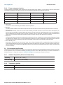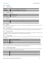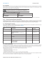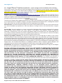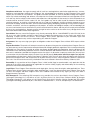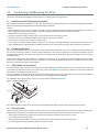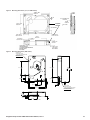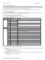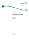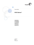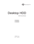
1
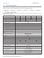
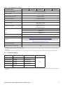
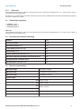
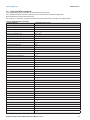
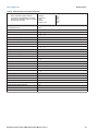
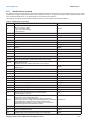
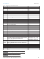
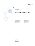
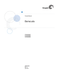
Product Manual
Seagate Enterprise NAS +SRS HDD
®
ST6000VN0011
ST5000VN0011
ST4000VN0011
ST3000VN0011
ST2000VN0011
Gen 2
100771866
Rev. A
January 2015
Document Revision History
Revision
Date
Description of Change
Rev. A
01/21/2015
Initial release.
© 2015 Seagate Technology LLC. All rights reserved.
Publication number: 100771866, Rev. A January 2015
Seagate, Seagate Technology and the Wave logo are registered trademarks of Seagate Technology LLC in the United
States and/or other countries. Enterprise NAS +SRS HDD v2 and SeaTools are either trademarks or registered trademarks of Seagate Technology LLC or one of its affiliated companies in the United States and/or other countries. All
other trademarks or registered trademarks are the property of their respective owners.
No part of this publication may be reproduced in any form without written permission of Seagate Technology LLC.
Call 877-PUB-TEK1(877-782-8351) to request permission.
When referring to drive capacity, one gigabyte, or GB, equals one billion bytes and one terabyte, or TB, equals one
trillion bytes. Your computer’s operating system may use a different standard of measurement and report a lower
capacity. In addition, some of the listed capacity is used for formatting and other functions, and thus will not be
available for data storage. Actual quantities will vary based on various factors, including file size, file format, features
and application software. Actual data rates may vary depending on operating environment and other factors. The
export or re-export of hardware or software containing encryption may be regulated by the U.S. Department of
Commerce, Bureau of Industry and Security (for more information, visit www.bis.doc.gov), and controlled for import
and use outside of the U.S. Seagate reserves the right to change, without notice, product offerings or specifications.
Contents
Seagate® Technology Support Services . . . . . . . . . . . . . . . . . . . . . . . . . . . . . . . . . . . . . . . . . . . . . . . . . . . .4
1.0
Introduction. . . . . . . . . . . . . . . . . . . . . . . . . . . . . . . . . . . . . . . . . . . . . . . . . . . . . . . . . . . . . . . . . . . . . .5
1.1
About the SATA interface . . . . . . . . . . . . . . . . . . . . . . . . . . . . . . . . . . . . . . . . . . . . . . . . . . . . .5
2.0
Drive Specifications . . . . . . . . . . . . . . . . . . . . . . . . . . . . . . . . . . . . . . . . . . . . . . . . . . . . . . . . . . . . . . .6
2.1
Specification summary tables . . . . . . . . . . . . . . . . . . . . . . . . . . . . . . . . . . . . . . . . . . . . . . . . . .6
2.2
Formatted capacityy . . . . . . . . . . . . . . . . . . . . . . . . . . . . . . . . . . . . . . . . . . . . . . . . . . . . . . . . .7
2.2.1
LBA mode . . . . . . . . . . . . . . . . . . . . . . . . . . . . . . . . . . . . . . . . . . . . . . . . . . . . . . . . .8
2.3
Default logical geometry . . . . . . . . . . . . . . . . . . . . . . . . . . . . . . . . . . . . . . . . . . . . . . . . . . . . . .8
2.4
Recording and interface technology . . . . . . . . . . . . . . . . . . . . . . . . . . . . . . . . . . . . . . . . . . . . .8
2.5
Physical characteristics . . . . . . . . . . . . . . . . . . . . . . . . . . . . . . . . . . . . . . . . . . . . . . . . . . . . . .8
2.6
Seek time. . . . . . . . . . . . . . . . . . . . . . . . . . . . . . . . . . . . . . . . . . . . . . . . . . . . . . . . . . . . . . . . . .9
2.7
Start/stop times . . . . . . . . . . . . . . . . . . . . . . . . . . . . . . . . . . . . . . . . . . . . . . . . . . . . . . . . . . . . .9
2.8
Power specifications . . . . . . . . . . . . . . . . . . . . . . . . . . . . . . . . . . . . . . . . . . . . . . . . . . . . . . . . .9
2.8.1
Power consumption . . . . . . . . . . . . . . . . . . . . . . . . . . . . . . . . . . . . . . . . . . . . . . . . . .9
2.8.2
Conducted noise . . . . . . . . . . . . . . . . . . . . . . . . . . . . . . . . . . . . . . . . . . . . . . . . . . .10
2.8.3
Voltage tolerance . . . . . . . . . . . . . . . . . . . . . . . . . . . . . . . . . . . . . . . . . . . . . . . . . . .10
2.8.4
Power-management modes . . . . . . . . . . . . . . . . . . . . . . . . . . . . . . . . . . . . . . . . . . .11
2.9
Environmental specifications . . . . . . . . . . . . . . . . . . . . . . . . . . . . . . . . . . . . . . . . . . . . . . . . . .11
2.9.1
Ambient Temperature (drive case temperature) . . . . . . . . . . . . . . . . . . . . . . . . . . .11
2.9.2
Temperature gradient. . . . . . . . . . . . . . . . . . . . . . . . . . . . . . . . . . . . . . . . . . . . . . . .11
2.9.3
Humidity . . . . . . . . . . . . . . . . . . . . . . . . . . . . . . . . . . . . . . . . . . . . . . . . . . . . . . . . . .12
2.9.4
Altitude . . . . . . . . . . . . . . . . . . . . . . . . . . . . . . . . . . . . . . . . . . . . . . . . . . . . . . . . . . .12
2.9.5
Shock . . . . . . . . . . . . . . . . . . . . . . . . . . . . . . . . . . . . . . . . . . . . . . . . . . . . . . . . . . . .12
2.9.6
Non-operating vibration . . . . . . . . . . . . . . . . . . . . . . . . . . . . . . . . . . . . . . . . . . . . . .12
2.10
Acoustics . . . . . . . . . . . . . . . . . . . . . . . . . . . . . . . . . . . . . . . . . . . . . . . . . . . . . . . . . . . . . . . . .13
2.10.1
Test for Prominent Discrete Tones (PDTs) . . . . . . . . . . . . . . . . . . . . . . . . . . . . . . .13
2.11
Electromagnetic immunity . . . . . . . . . . . . . . . . . . . . . . . . . . . . . . . . . . . . . . . . . . . . . . . . . . . .13
2.12
MTBF and Warranty . . . . . . . . . . . . . . . . . . . . . . . . . . . . . . . . . . . . . . . . . . . . . . . . . . . . . . . .13
2.13
Seagate® Rescue™ Data Recovery Service – 3-year coverage
(concurrent with bare drive warranty) . . . . . . . . . . . . . . . . . . . . . . . . . . . . . . . . . . . . . . . . . . .14
2.14
Agency certification . . . . . . . . . . . . . . . . . . . . . . . . . . . . . . . . . . . . . . . . . . . . . . . . . . . . . . . . .16
2.14.1
Safety certification . . . . . . . . . . . . . . . . . . . . . . . . . . . . . . . . . . . . . . . . . . . . . . . . . .16
2.14.2
Electromagnetic compatibility. . . . . . . . . . . . . . . . . . . . . . . . . . . . . . . . . . . . . . . . . .16
2.14.3
FCC verification . . . . . . . . . . . . . . . . . . . . . . . . . . . . . . . . . . . . . . . . . . . . . . . . . . . .16
2.15
Environmental protection . . . . . . . . . . . . . . . . . . . . . . . . . . . . . . . . . . . . . . . . . . . . . . . . . . . . .17
2.15.1
European Union Restriction of Hazardous Substances (RoHS) Directive . . . . . . . .17
2.15.2
China Restriction of Hazardous Substances (RoHS) Directive . . . . . . . . . . . . . . .17
2.16
Corrosive environment. . . . . . . . . . . . . . . . . . . . . . . . . . . . . . . . . . . . . . . . . . . . . . . . . . . . . . .17
3.0
Configuring and Mounting the Drive . . . . . . . . . . . . . . . . . . . . . . . . . . . . . . . . . . . . . . . . . . . . . . . .18
3.1
Handling and static-discharge precautions . . . . . . . . . . . . . . . . . . . . . . . . . . . . . . . . . . . . . . .18
3.2
Configuring the drive . . . . . . . . . . . . . . . . . . . . . . . . . . . . . . . . . . . . . . . . . . . . . . . . . . . . . . . .18
3.3
SATA cables and connectors . . . . . . . . . . . . . . . . . . . . . . . . . . . . . . . . . . . . . . . . . . . . . . . . .18
3.4
Drive mounting. . . . . . . . . . . . . . . . . . . . . . . . . . . . . . . . . . . . . . . . . . . . . . . . . . . . . . . . . . . . .18
4.0
SATA Interface . . . . . . . . . . . . . . . . . . . . . . . . . . . . . . . . . . . . . . . . . . . . . . . . . . . . . . . . . . . . . . . . . .20
4.1
Hot-Plug compatibility . . . . . . . . . . . . . . . . . . . . . . . . . . . . . . . . . . . . . . . . . . . . . . . . . . . . . . .20
4.2
SATA device plug connector pin definitions . . . . . . . . . . . . . . . . . . . . . . . . . . . . . . . . . . . . . .20
4.3
Supported ATA commands . . . . . . . . . . . . . . . . . . . . . . . . . . . . . . . . . . . . . . . . . . . . . . . . . . .21
4.3.1
Identify Device command . . . . . . . . . . . . . . . . . . . . . . . . . . . . . . . . . . . . . . . . . . . . .23
4.3.2
Set Features command . . . . . . . . . . . . . . . . . . . . . . . . . . . . . . . . . . . . . . . . . . . . . .26
4.3.3
S.M.A.R.T. commands . . . . . . . . . . . . . . . . . . . . . . . . . . . . . . . . . . . . . . . . . . . . . . .27
Seagate Enterprise NAS +SRS HDD Product Manual, Rev. A
2
Figures
Figure 1
Figure 2
Figure 3
Attaching SATA cabling . . . . . . . . . . . . . . . . . . . . . . . . . . . . . . . . . . . . . . . . . . . . . . . . . . . . . 18
Mounting dimensions (2, 3, 4 & 5TB models) . . . . . . . . . . . . . . . . . . . . . . . . . . . . . . . . . . . . 19
Mounting dimensions (6TB model) . . . . . . . . . . . . . . . . . . . . . . . . . . . . . . . . . . . . . . . . . . . . 19
Seagate Enterprise NAS +SRS HDD Product Manual, Rev. A
3
Seagate Technology Support Services
®
For information regarding online support and services, visit: http://www.seagate.com/about/contact-us/technical-support/
Available services include:
• Presales & Technical support
• Global Support Services telephone numbers & business hours
• Authorized Service Centers
For information regarding Warranty Support, visit: http://www.seagate.com/support/warranty-and-replacements/
For information regarding data recovery services, visit: http://www.seagate.com/services-software/data-recovery-services/
For Seagate OEM and Distribution partner portal, visit: http://www.seagate.com/partners
For Seagate reseller portal, visit: http://www.seagate.com/partners/my-spp-dashboard/
Seagate Enterprise NAS +SRS HDD Product Manual, Rev. A
4
1.0
Introduction
This manual describes the functional, mechanical and interface specifications for the following: Seagate® Enterprise NAS +SRS HDD
model drives:
+SRS models
ST6000VN0011
ST5000VN0011
ST4000VN0011
ST3000VN0011
ST2000VN0011
These drives provide the following key features:
• Off-the-shelf compatibility
• Rated for 1M hours MTBF
• 24x7 capability
• Performance-tuned for RAID applications
• Balance technology to support multiple drives in a system
• Quiet acoustic performance
• Low activity and idle power
• Supports ATA8 streaming commands
• TGMR recording technology provides the drives with increased areal density.
• State-of-the-art cache and on-the-fly error-correction algorithms
• Native Command Queuing with command ordering to increase performance in demanding applications
• Full-track multiple-sector transfer capability without local processor intervention
• Compliant with RoHS requirements in China and Europe
• SeaTools diagnostic software performs a drive self-test that eliminates unnecessary drive returns.
• Support for S.M.A.R.T. drive monitoring and reporting
• Supports latching SATA cables and connectors
• Worldwide Name (WWN) capability uniquely identifies the drive
1.1
About the SATA interface
The Serial ATA (SATA) interface provides several advantages over the traditional (parallel) ATA interface. The primary advantages
include:
• Easy installation and configuration with true plug-and-play connectivity. It is not necessary to set any jumpers or other configuration
options.
• Thinner and more flexible cabling for improved enclosure airflow and ease of installation.
• Scalability to higher performance levels.
In addition, SATA makes the transition from parallel ATA easy by providing legacy software support. SATA was designed to allow users
to install a SATA host adapter and SATA disk drive in the current system and expect all of the existing applications to work as normal.
The SATA interface connects each disk drive in a point-to-point configuration with the SATA host adapter. There is no master/slave
relationship with SATA devices like there is with parallel ATA. If two drives are attached on one SATA host adapter, the host operating
system views the two devices as if they were both “masters” on two separate ports. This essentially means both drives behave as if
they are Device 0 (master) devices.
The SATA host adapter and drive share the function of emulating parallel ATA device behavior to provide backward compatibility with
existing host systems and software. The Command and Control Block registers, PIO and DMA data transfers, resets, and interrupts are
all emulated.
The SATA host adapter contains a set of registers that shadow the contents of the traditional device registers, referred to as the
Shadow Register Block. All SATA devices behave like Device 0 devices. For additional information about how SATA emulates parallel
ATA, refer to the “Serial ATA International Organization: Serial ATA Revision 3.0”. The specification can be downloaded from www.sataio.org.
Note
The host adapter may, optionally, emulate a master/slave environment to host software where two
devices on separate SATA ports are represented to host software as a Device 0 (master) and Device 1
(slave) accessed at the same set of host bus addresses. A host adapter that emulates a master/slave
environment manages two sets of shadow registers. This is not a typical SATA environment.
Seagate Enterprise NAS +SRS HDD Product Manual, Rev. A
5
www.seagate.com
2.0
Drive Specifications
Drive Specifications
Unless otherwise noted, all specifications are measured under ambient conditions, at 25°C, and nominal power. For convenience, the
phrases the drive and this drive are used throughout this manual to indicate the following drive models:
+SRS models
2.1
ST6000VN0011
ST5000VN0011
ST4000VN0011
ST3000VN0011
ST2000VN0011
Specification summary tables
The specifications listed in Table 1 are for quick reference. For details on specification measurement or definition, refer to the
appropriate section of this manual.
Table 1 Drive specifications summary
Drive Specification*
ST6000VN0011
ST5000VN0011
ST4000VN0011
ST3000VN0011
ST2000VN0011
Formatted capacity (512 bytes/sector)**
6000GB (6TB)
5000GB (5TB)
4000GB (4TB)
3000GB (3TB)
2000GB (2TB)
Guaranteed sectors
11,721,045,168
9,767,541,168
7,814,037,168
5,860,533,168
3,907,029,168
Heads
12
10
8
4
Disks
6
5
4
2
Bytes per sector
(4K physical emulated at 512-byte sectors)
4096
Default sectors per track
63
Default read/write heads
16
Default cylinders
16,383
Recording density (max)
1941kFCI
Track density (avg)
340ktracks/in
Areal density (avg)
642Gb/in2
Internal data transfer rate (max)
2347Mb/s
Average data rate, read/write (MB/s)
154MB/s
Maximum sustained data rate, OD read
(MB/s)
216MB/s
PIO modes: 0 to 4
Multiword DMA modes: 0 to 2
Ultra DMA modes 0 to 6
ATA data-transfer modes supported
I/O data-transfer rate (max)
600MB/s
Cache buffer
128MB
Height (max)
26.1mm / 1.028 in
Width (max)
101.6mm /4.0 in (+ 0.010 in)
Length (max)
146.99mm / 5.787 in
Weight (typical)
780g / 1.72 lb
700g / 1.54 lb
Average latency
620g / 1.37 lb
Power-on to ready (max)
26.0s
Standby to ready (max)
<20.0s
Average seek, read (typical)
Average seek, write (typical)
<8.5ms typical
<9.5ms typical
Startup current (typical) 12V
<=1.8A
Voltage tolerance (including noise)
Ambient temperature
(drive case temperature)
Temperature gradient
Relative humidity
Relative humidity gradient (max)
Seagate Enterprise NAS +SRS HDD Product Manual, Rev. A
540g / 1.19 lb
4.0ms
5V: ±5%
12V: +10%/ -7.5%
0° to 70°C (operating)
–40° to 70°C (non-operating)
20°C per hour max (operating)
30°C per hour max (nonoperating)
5% to 90% (operating)
5% to 95% (nonoperating)
30% per hour
6
Table 1 Drive specifications summary
Drive Specification*
ST6000VN0011
ST5000VN0011
ST4000VN0011
ST3000VN0011
ST2000VN0011
37.7°C max (operating)
40.0°C max (nonoperating)
Wet bulb temperature (max)
Altitude, operating
–304m to 3048m
(–1000 ft to 10,000 ft)
Altitude, non-operating
(below mean sea level, max)
–304m to12,192m
(–1000ft to 40,000+ ft)
70 Gs at 2ms (read)
40 Gs at 2ms (write)
Operational shock (max)
Non-operational shock (max)
300 Gs at 2ms
2Hz to 22Hz: 0.25 Gs, Limited displacement
22Hz to 350Hz: 0.50 Gs
350Hz to 500Hz: 0.25 Gs
Vibration, operating
5Hz to 22Hz: 3.0 Gs
22Hz to 350Hz: 3.0 Gs
350Hz to 500Hz: 3.0 Gs
Vibration, non-operating
Drive acoustics, sound power
Idle***
2.5 bels (typical)
2.6 bels (max)
Seek
2.6 bels (typical)
2.7 bels (max)
1 per 1015 bits read
Non-recoverable read errors
Mean Time Between Failure (MTBF)
1,000,000 hrs
To determine the warranty for a specific drive, use a web browser to access the following web page:
http://www.seagate.com/support/warranty-and-replacements/
From this page, click on “Check to see if the drive is under Warranty”. Users will be asked to provide
the drive serial number, model number (or part number) and country of purchase. The system will
display the warranty information for the drive.
Warranty
Load/unload cycles
(25°C, 50% rel. humidity)
600,000 at 25°C, 50% rel. humidity
Supports hotplug operation per the
Serial ATA Revision 3.0 specification
Yes
*All specifications above are based on native configurations.
** One GB equals one billion bytes and 1TB equals one trillion bytes when referring to hard drive capacity. Accessible capacity may vary depending on operating environment
and formatting.
* ** During periods of drive idle, some offline activity may occur according to the S.M.A.R.T. specification, which may increase acoustic and power to operational levels.
2.2
Formatted capacity
Model
Formatted capacity*
Guaranteed sectors
ST6000VN0011
6000GB
11,721,045,168
ST5000VN0011
5000GB
9,767,541,168
ST4000VN0011
4000GB
7,814,037,168
ST3000VN0011
3000GB
5,860,533,168
ST2000VN0011
2000GB
3,907,029,168
Bytes per sector
4K
*One GB equals one billion bytes and 1TB equals one trillion bytes when referring to hard drive capacity. Accessible capacity may vary depending on operating environment
and formatting.
Seagate Enterprise NAS +SRS HDD Product Manual, Rev. A
7
www.seagate.com
2.2.1
Drive Specifications
LBA mode
When addressing these drives in LBA mode, all blocks (sectors) are consecutively numbered from 0 to n–1, where n is the number of
guaranteed sectors as defined above.
See Section 4.3.1, "Identify Device command" (words 60-61 and 100-103) for additional information about 48-bit addressing support of
drives with capacities over 137GB.
2.3
Default logical geometry
• Cylinders: 16,383
• Read/write heads: 16
• Sectors per track: 63
LBA mode
When addressing these drives in LBA mode, all blocks (sectors) are consecutively numbered from 0 to n–1, where n is the number of
guaranteed sectors as defined above.
2.4
Recording and interface technology
Interface
SATA
Recording method
TGMR
Recording density (kFCI)
1941
Track density (ktracks/inch avg)
340
Areal density (Gb/in2)
642
Internal data transfer rate (Mb/s max)
2347
Maximum sustained data transfer rate, OD read (MB/s)
216
Average data rate, read/write (MB/s)
154
I/O data-transfer rate (MB/s max)
600
2.5
Physical characteristics
Maximum height
26.11mm / 1.028 in
Maximum width
101.6mm / 4.0 in (± 0.010 in)
Maximum length
146.99mm / 5.787 in
Typical weight
6TB
780g / 1.72 lb
5TB
700g / 1.54 lb
4TB
620g / 1.372 lb
3TB
2TB
Cache buffer
Seagate Enterprise NAS +SRS HDD Product Manual, Rev. A
540g / 1.19 lb
128MB
8
www.seagate.com
2.6
Drive Specifications
Seek time
Seek measurements are taken with nominal power at 25°C ambient temperature. All times are measured using drive diagnostics. The
specifications in the table below are defined as follows:
• Track-to-track seek time is an average of all possible single-track seeks in both directions.
• Average seek time is a true statistical random average of at least 5000 measurements of seeks between random tracks, less
overhead.
Typical seek times (ms)
Read
Write
Track-to-track
1.0
1.2
Average
8.5
9.5
Average latency
Note
2.7
4.0
These drives are designed to consistently meet the seek times represented in this manual. Physical seeks,
regardless of mode (such as track-to-track and average), are expected to meet the noted values. However,
due to the manner in which these drives are formatted, benchmark tests that include command overhead or
measure logical seeks may produce results that vary from these specifications.
Start/stop times
The start/stop times listed below.
Power-on to ready
(in seconds)
15 (typical)
26 (max)
Standby to ready
(in seconds)
15 (typical)
20 (max)
Ready to spindle stop
(in seconds)
10 (typical)
11 (max)
Time-to-ready may be longer than normal if the drive power is removed without going through normal OS powerdown procedures.
2.8
Power specifications
The drive receives DC power (+5V or +12V) through a native SATA power connector. Refer to Figure 1 on page 18.
2.8.1
Power consumption
Power requirements for the drives are listed in Table 2. Typical power measurements are based on an average of drives tested, under
nominal conditions, using 5.0V and 12.0V input voltage at 25°C ambient temperature.
• Spinup power
Spinup power is measured from the time of power-on to the time that the drive spindle reaches operating speed.
• Read/write power and current
Read/write power is measured with the heads on track, based on a 16-sector write followed by a 32-ms delay, then a 16-sector read
followed by a 32-ms delay.
• Operating power and current
Operating power is measured using 40 percent random seeks, 40 percent read/write mode (1 write for each 10 reads) and 20 percent drive idle mode.
• Idle mode power
Idle mode power is measured with the drive up to speed, with servo electronics active and with the heads in a random track location.
• Standby mode
During Standby mode, the drive accepts commands, but the drive is not spinning, and the servo and read/write electronics are in
power-down mode.
Seagate Enterprise NAS +SRS HDD Product Manual, Rev. A
9
www.seagate.com
Drive Specifications
Table 2 DC power requirements
Power dissipation (6/5TB models)
Avg (25° C)
Avg 5V typ
Avg 12V typ
Spinup
—
—
<=1.8A
Idle* †
7.20W
0.20A
0.52A
Operating
9.00W
0.24A
0.65A
Standby
0.60W
0.12A
0.01A
Sleep
0.60W
0.12A
0.01A
Power dissipation (4/3TB models)
Avg (25° C)
Avg 5V typ
Avg 12V typ
Spinup
—
—
<=1.8A
Idle* †
5.90W
0.30A
0.36A
Operating
6.70W
0.357A
0.41A
Standby
0.60W
0.12A
0.01A
Sleep
0.60W
0.12A
0.01A
Power dissipation (2TB models)
Avg (25° C)
Avg 5V typ
Avg 12V typ
Spinup
—
—
<=1.8A
Idle* †
3.70W
0.18A
0.23A
Operating
5.30W
0.355A
0.297A
Standby
0.60W
0.12A
0.01A
Sleep
0.60W
0.12A
0.01A
Table 3 DC power requirements
Table 4 DC power requirements
* During periods of drive idle, some offline activity may occur according to the S.M.A.R.T. specification, which may increase acoustic and power to operational levels.
†5W IDLE with DIPLM Enabled
2.8.2
Conducted noise
Input noise ripple is measured at the host system power supply across an equivalent 80-ohm resistive load on the +12 volt line or an
equivalent 15-ohm resistive load on the +5 volt line.
• Using 12-volt power, the drive is expected to operate with a maximum of 120 mV peak-to-peak square-wave injected noise at up to
10MHz.
• Using 5-volt power, the drive is expected to operate with a maximum of 100 mV peak-to-peak square-wave injected noise at up to
10MHz.
Note
2.8.3
Equivalent resistance is calculated by dividing the nominal voltage by the typical RMS read/write current.
Voltage tolerance
Voltage tolerance (including noise):
• 5V
±5%
• 12V
+10%/-7.5%
Seagate Enterprise NAS +SRS HDD Product Manual, Rev. A
10
www.seagate.com
2.8.4
Drive Specifications
Power-management modes
The drive provides programmable power management to provide greater energy efficiency. In most systems, users can control power
management through the system setup program. The drive features the following power-management modes:
Power modes
Heads
Spindle
Buffer
Active
Tracking
Rotating
Enabled
Idle
Tracking
Rotating
Enabled
Standby
Parked
Stopped
Enabled
Sleep
Parked
Stopped
Disabled
• Active mode
The drive is in Active mode during the read/write and seek operations.
• Idle mode
The buffer remains enabled, and the drive accepts all commands and returns to Active mode any time disk access is necessary.
• Standby mode
The drive enters Standby mode when the host sends a Standby Immediate command. If the host has set the standby timer, the
drive can also enter Standby mode automatically after the drive has been inactive for a specifiable length of time. The standby timer
delay is established using a Standby or Idle command. In Standby mode, the drive buffer is enabled, the heads are parked and the
spindle is at rest. The drive accepts all commands and returns to Active mode any time disk access is necessary.
• Sleep mode
The drive enters Sleep mode after receiving a Sleep command from the host. In Sleep mode, the drive buffer is disabled, the heads
are parked and the spindle is at rest. The drive leaves Sleep mode after it receives a Hard Reset or Soft Reset from the host. After
receiving a reset, the drive exits Sleep mode and enters Standby mode with all current translation parameters intact.
• Idle and Standby timers
Each time the drive performs an Active function (read, write or seek), the standby timer is reinitialized and begins counting down
from its specified delay times to zero. If the standby timer reaches zero before any drive activity is required, the drive makes a transition to Standby mode. In both Idle and Standby mode, the drive accepts all commands and returns to Active mode when disk
access is necessary.
2.9
Environmental specifications
This section provides the temperature, humidity, shock, and vibration specifications for Desktop HDDs. Ambient temperature is defined
as the temperature of the environment immediately surrounding the drive. Above 1000ft. (305 meters), the maximum temperature is
derated linearly by 1°C every 1000 ft. Refer to Section 3.4 on page 18 for base plate measurement location.
2.9.1
Ambient Temperature (drive case temperature)
Operating
0° to 70°C (32° to 158°F)
Non-operating
–40° to 70°C (–40° to 158°F)
2.9.2
Temperature gradient
Operating
20°C per hour (68°F per hour max), without condensation
Non-operating
30°C per hour (86°F per hour max)
Seagate Enterprise NAS +SRS HDD Product Manual, Rev. A
11
www.seagate.com
Drive Specifications
2.9.3
Humidity
2.9.3.1
Relative humidity
Operating
5% to 90% non-condensing (30% per hour max)
Nonoperating
5% to 95% non-condensing (30% per hour max)
2.9.3.2
Wet bulb temperature
Operating
37.7°C (99.9°F max)
Non-operating
40°C (104°F max)
2.9.4
Altitude
Operating
–304m to 3048m (–1000 ft. to 10,000 ft.)
Non-operating
–304m to 12,192m (–1000 ft. to 40,000+ ft.)
2.9.5
Shock
All shock specifications assume that the drive is mounted securely with the input shock applied at the drive mounting screws. Shock
may be applied in the X, Y or Z axis.
2.9.5.1
Operating shock
These drives comply with the performance levels specified in this document when subjected to a maximum operating shock of 70 Gs
based on half-sine shock pulses of 2ms during read operations. Shocks should not be repeated more than two times per second.
2.9.5.2
Non-operating shock
The non-operating shock level that the drive can experience without incurring physical damage or degradation in performance when
subsequently put into operation is 300 Gs based on a non-repetitive half-sine shock pulse of
2ms duration.
2.9.5.3
Operating vibration
The maximum vibration levels that the drive may experience while meeting the performance standards specified in this document are
specified below.
2Hz to 22Hz
0.25 Gs (Limited displacement)
22Hz to 350Hz
0.50 Gs
350Hz to 500Hz
0.25 Gs
All vibration specifications assume that the drive is mounted securely with the input vibration applied at the drive mounting screws.
Vibration may be applied in the X, Y or Z axis. Throughput may vary if improperly mounted.
2.9.6
Non-operating vibration
The maximum non-operating vibration levels that the drive may experience without incurring physical damage or degradation in
performance when subsequently put into operation are specified below.
5Hz to 22Hz
3.0 Gs (Limited displacement)
22Hz to 350Hz
3.0 Gs
350Hz to 500Hz
3.0 Gs
Seagate Enterprise NAS +SRS HDD Product Manual, Rev. A
12
www.seagate.com
Drive Specifications
2.10 Acoustics
Drive acoustics are measured as overall A-weighted acoustic sound power levels (no pure tones). All measurements are consistent
with ISO document 7779. Sound power measurements are taken under essentially free-field conditions over a reflecting plane. For all
tests, the drive is oriented with the cover facing upward.
Note
For seek mode tests, the drive is placed in seek mode only.
The number of seeks per second is defined by the following equation:
(Number of seeks per second = 0.4 / (average latency + average access time
Table 5 Fluid Dynamic Bearing (FDB) motor acoustics
Idle*
Seek
2.5 bels (typical)
2.6 bels (max)
2.6 bels (typical)
2.7 bels (max)
* During periods of drive idle, some offline activity may occur according to the S.M.A.R.T. specification, which may increase acoustic and power to operational levels.
2.10.1
Test for Prominent Discrete Tones (PDTs)
Seagate follows the ECMA-74 standards for measurement and identification of PDTs. An exception to this process is the use of the
absolute threshold of hearing. Seagate uses this threshold curve (originated in ISO 389-7) to discern tone audibility and to compensate
for the inaudible components of sound prior to computation of tone ratios according to Annex D of the ECMA-74 standards.
2.11 Electromagnetic immunity
When properly installed in a representative host system, the drive operates without errors or degradation in performance when
subjected to the radio frequency (RF) environments defined in Table 6.
Table 6 Radio frequency environments
Test
Description
Performance
level
Reference
standard
Electrostatic discharge
Contact, HCP, VCP: ± 4 kV; Air: ± 8 kV
B
EN61000-4-2: 95
Radiated RF immunity
80MHz to 1,000MHz, 3 V/m,
80% AM with 1kHz sine
900MHz, 3 V/m, 50% pulse modulation @
200Hz
A
EN61000-4-3: 96
ENV50204: 95
Electrical fast transient
± 1 kV on AC mains, ± 0.5 kV on external I/O
B
EN61000-4-4: 95
Surge immunity
± 1 kV differential, ± 2 kV common,
AC mains
B
EN61000-4-5: 95
Conducted RF immunity
150kHz to 80MHz, 3 Vrms, 80% AM with 1kHz
sine
A
EN61000-4-6: 97
Voltage dips, interrupts
0% open, 5 seconds
0% short, 5 seconds
40%, 0.10 seconds
70%, 0.01 seconds
C
C
C
B
EN61000-4-11: 94
2.12 MTBF and Warranty
The product will achieve a Mean Time Between Failure Rate (MTBF) of 1,000,000 hours when operated in an environment of ambient
air temperatures of 25°C. Operation at temperatures outside the specifications shown in Section 2.9, "Environmental specifications."
may increase the product MTBF. MTBF is a population statistic that is not relevant to individual units.
MTBF specifications are based on the following assumptions for NAS environments:
• 8760 power-on hours per year
• 10,000 average motor start/stop cycles per year
• Operations at nominal voltages
• Temperatures outside the specifications in page 11 may reduce the product reliability.
Operation at excessive I/O duty cycle may degrade product reliability. The NAS environment of power-on hours, temperature, and I/O
duty cycle affect the product MTBF. The MTBF will be degraded if used in an enterprise application.
Seagate Enterprise NAS +SRS HDD Product Manual, Rev. A
13
www.seagate.com
Drive Specifications
2.13 Seagate® Rescue™ Data Recovery Service – 3-year coverage (concurrent with bare drive warranty)
If you suffer a data loss event within the three year Seagate Rescue Data Recovery warranty period, and you are eligible
to participate in and submit a case under the Rescue program, contact SRS at (1-800-723-1183) in the US, or if you are
calling from outside the US please visit our website for numbers in your local and language:
http://www.seagate.com/contacts/contact-numbers/.
In addition, you may visit http://rescueandreplace.seagate.com/contact.jsp to obtain information regarding how to
contact a recovery expert online or by telephone from your location. An SRS representative will review your case to
confirm your eligibility, and to assess whether your data may be recoverable by remote recovery services or whether you
will need to send your device to SRS for in-lab servicing.
Rescue™ General Terms
These Rescue™ General Terms together with the Rescue™ FAQ’s make up the Rescue™ Program Terms. By submitting
a case under the Rescue™ program (“Program”) you agree to be bound by the Program Terms, including these General
Terms and the FAQ. You must be a legal resident of the US to participate in the Program.
Communications. All communications relating to your request will be available on our web site in your account and sent
via e-mail to the address you provide to us unless you request, in writing, to receive such communications via regular
mail.
Personal Data. You must provide true, accurate and complete information about yourself as prompted by the request
form, including, without limitation, your name, address, e-mail address, and telephone number, as applicable
(collectively, “Personal Data”). You must maintain and promptly update your Personal Data. You acknowledge that we
may send you important information and notices regarding your requests by e-mail and that we shall have no liability
associated with or arising from your failure to maintain accurate Personal Data.
Capacity; Legal Rights; Indemnity. You represent to SRS that you are of the legal age of majority in your state or
country of residence, with the full capacity to agree to these Program Terms. You warrant that you are the legal owner or
the authorized representative of the legal owner of the device you submit to SRS (the “Device”) and data. You warrant
that the data on the Device is legal and that you have the unrestricted legal right to (a) give us remote access to the data,
(b) have the data recovered and reproduced on a backup medium, (c) receive the recovered data, and (d) agree to these
Program Terms. You will defend and indemnify us (including our directors, officers, employees, agents, delegates, and
contractors) from any claims or actions relating to the Device or data, or your rights or lack of rights thereto.
Confidentiality. We will protect the confidentiality of your data against unauthorized disclosure using the same degree
of care as we use to protect our own confidential information.
Disclaimer of Warranties, Representations and Guarantees. WE PROVIDE THE PROGRAM AND ANY SERVICES
PROVIDED OR ATTEMPTED HEREUNDER “AS IS,” WITH ALL FAULTS, AT YOUR SOLE RISK. WE DO NOT
EXTEND ANY EXPRESS WARRANTIES, REPRESENTATIONS, CONDITIONS OR GUARANTEES REGARDING OUR
RESCUE SERVICES OR ANY RESULTS THEREOF. TO THE MAXIMUM EXTENT PERMITTED BY APPLICABLE
LAW AND SUBJECT TO ANY STATUTORY WARRANTIES THAT CANNOT BE EXCLUDED, WE EXPRESSLY
DISCLAIM ALL IMPLIED WARRANTIES, INCLUDING ANY IMPLIED WARRANTY OR CONDITION OF
MERCHANTABILITY, WARRANTY OF FITNESS FOR A PARTICULAR PURPOSE, OR WARRANTY OF ACCURACY
OR COMPLETENESS WITH RESPECT TO THIS PROGRAM AND SERVICES. This Program and Disclaimer is
unrelated to, and does not affect any warranties relating to your Device that we or the seller may have extended to you.
Limitation of Liability. WE WILL NOT BE LIABLE FOR ANY HARM CAUSED, UNLESS YOU PROVE THAT WE
CAUSED SUCH HARM INTENTIONALLY. WITHOUT LIMITING THE GENERALITY OF THE FOREGOING, WE WILL
NOT BE LIABLE FOR THE CONDITION, EXISTENCE, OR LOSS OF THE DATA YOU SEND US OR THE DATA WE
RECOVER (IF ANY), ANY LOSS OF REVENUE OR LOSS OF PROFITS, OR ANY INDIRECT, SPECIAL, INCIDENTAL,
OR CONSEQUENTIAL DAMAGES HOWEVER CAUSED. TO THE MAXIMUM EXTENT PERMITTED BY
APPLICABLE LAW, THIS LIMITATION SHALL APPLY TO ANY AND ALL DAMAGES, REGARDLESS OF THE LEGAL
THEORY ON WHICH THEY ARE ASSERTED (INCLUDING, WITHOUT LIMITATION, CONTRACT, BREACH OF
CONTRACT, AND TORT), AND REGARDLESS OF WHETHER WE HAVE BEEN ADVISED OF THE POSSIBILITY OF
LOSS OR DAMAGES - UNLESS YOU PROVE THAT SRS CAUSED DAMAGES TO YOU INTENTIONALLY. TO THE
MAXIMUM EXTENT PERMITTED BY APPLICABLE LAW, THE AMOUNT OF OUR LIABILITY WILL NOT EXCEED
THE TOTAL PRICE YOU ACTUALLY PAY FOR THE DEVICE, THE ESSENTIAL PURPOSE OF WHICH IS TO LIMIT
OUR LIABILITY ARISING FROM OR RELATED TO THE PROGRAM AND ANY DATA RECOVERY SERVICES. THIS
ALLOCATION OF RISK IS REFLECTED IN THE PRICE CHARGED FOR THIS PROGRAM OR SERVICES, IF ANY.
YOU ACKNOWLEDGE THAT THE PRICE OF THIS PROGRAM WOULD BE MUCH GREATER IF WE UNDERTOOK
MORE EXTENSIVE LIABILITY. THIS PARAGRAPH WILL APPLY NOTWITHSTANDING ANY OTHER PROVISIONS IN
THESE TERMS, OR THE FAILURE OF ANY REMEDY.
Seagate Enterprise NAS +SRS HDD Product Manual, Rev. A
14
www.seagate.com
Drive Specifications
Compliance with Laws. You agree to comply with all such laws and regulations and all other applicable laws, statutes,
ordinances and regulations relating to the Program. You acknowledge that violations of these Program Terms could
subject you to criminal or civil penalties. The goods licensed or provided, or services provided, through the Program,
which may include technology and software, are subject to the customs and export control laws and regulations of the
U.S. and may also be subject to the customs and export laws and regulations of the country in which the products are
manufactured or received. Further, under U.S. law, such goods may not be sold, leased or otherwise transferred to
restricted countries, or used by a restricted end-user or an end-user engaged in activities related to weapons of mass
destruction including, without limitation, activities related to designing, developing, producing or using nuclear weapons,
materials, or facilities, missiles or supporting missile projects, or chemical or biological weapons. You acknowledge you
are not a restricted end-user or involved in any of the restricted activities above, and that you will comply with and abide
by these laws and regulations. Seagate reserves the right to refuse service to or the return of any storage devices that
have been determined to violate these regulations.
Cancellation. You may cancel the Program at any time by contacting SRS at 1-800-SEAGATE (1-800-475-0143) in the
US, or at such other number available at http://services.seagate.com/contact.aspx, or you simply may refrain from
submitting a request for Rescue services. These Program Terms remain applicable to your and SRS’s rights and
obligations with respect to any services requested by you under this Program.
Assignment. You may not assign your rights or obligations under these Program Terms without SRS’ express written
consent.
Dispute Resolution. The parties will attempt to resolve any dispute arising out of or related to these Program Terms or
any data recovery services requested or attempted hereunder through good faith negotiation. To the extent permitted by
applicable law, if the parties are unable to resolve the dispute through good faith negotiation, then the dispute will be
submitted to final and binding arbitration with the Judicial Arbitration and Mediation Services. Each party will bear its
own costs in arbitration, provided that Seagate reserves the right, in its discretion, to pre-pay certain fees you may incur
in connection with the arbitration subject to refund if you do not prevail. Both parties waive their rights to a jury trial.
All proceedings will take place in Santa Clara County, California, USA. The laws of the State of California will exclusively
govern these Program Terms and our provision of any data recovery services, without regard to California's conflicts of
laws rules. You consent to the exclusive jurisdiction of the courts located in Santa Clara County, California, USA.
Severability. If any provision of these Program Terms is held invalid, illegal or unenforceable, such provision shall be
enforced to the fullest extent permitted by applicable law and the validity, legality and enforceability of the remaining
provisions shall not be affected thereby.
Legal Effect. These Program Terms describe certain legal rights. You may have other rights under applicable law. These
Program Terms do not change your rights under applicable law if such laws do not permit these Program Terms to do
so. Also, the Program and these Program Terms are in addition and unrelated to any rights you may have under a
Seagate warranty statement.
SRS Companies. The following SRS companies may provide the services described in these Program Terms:
(a) Seagate Technology LLC, with offices at 3101 Jay Street, Suite 110, Santa Clara, California 95054; (b) Seagate
Technology Canada Inc., with offices at 2421 Bristol Circle, Suite A100, Oakville, Ontario, Canada L6H 5S9; and/or
(c) Seagate Technology (Netherlands) B.V., with offices at Koolhovenlaan 1, 1119 PA, Schiphol-Rijk, The Netherlands.
Seagate Enterprise NAS +SRS HDD Product Manual, Rev. A
15
www.seagate.com
Drive Specifications
2.14 Agency certification
2.14.1
Safety certification
These products are certified to meet the requirements of UL60950-1, CSA60950-1 and EN60950 and so marked as to the certify
agency.
2.14.2
Electromagnetic compatibility
Hard drives that display the CE mark comply with the European Union (EU) requirements specified in the Electromagnetic Compatibility
Directive (2004/108/EC) as put into place 20 July 2007. Testing is performed to the levels specified by the product standards for
Information Technology Equipment (ITE). Emission levels are defined by EN 55022, Class B and the immunity levels are defined by EN
55024.
Drives are tested in representative end-user systems. Although CE-marked Seagate drives comply with the directives when used in the
test systems, we cannot guarantee that all systems will comply with the directives. The drive is designed for operation inside a properly
designed enclosure, with properly shielded I/O cable (if necessary) and terminators on all unused I/O ports. Computer manufacturers
and system integrators should confirm EMC compliance and provide CE marking for their products.
Korean RRL
If these drives have the Korean Communications Commission (KCC) logo, they comply with paragraph 1 of Article 11 of the
Electromagnetic Compatibility control Regulation and meet the Electromagnetic Compatibility (EMC) Framework requirements of the
Radio Research Laboratory (RRL) Communications Commission, Republic of Korea.
These drives have been tested and comply with the Electromagnetic Interference/Electromagnetic Susceptibility (EMI/EMS) for Class
B products. Drives are tested in a representative, end-user system by a Korean-recognized lab.
• Family name: Enterprise NAS +SRS HDD v2
• Certificate number: In process
Australian C-Tick (N176)
If these models have the C-Tick marking, they comply with the Australia/New Zealand Standard AS/NZ CISPR22 and meet the
Electromagnetic Compatibility (EMC) Framework requirements of the Australian Communication Authority (ACA).
2.14.3
FCC verification
These drives are intended to be contained solely within a personal computer or similar enclosure (not attached as an external device).
As such, each drive is considered to be a subassembly even when it is individually marketed to the customer. As a subassembly, no
Federal Communications Commission verification or certification of the device is required.
Seagate has tested this device in enclosures as described above to ensure that the total assembly (enclosure, disk drive, motherboard,
power supply, etc.) does comply with the limits for a Class B computing device, pursuant to Subpart J, Part 15 of the FCC rules.
Operation with non-certified assemblies is likely to result in interference to radio and television reception.
Radio and television interference. This equipment generates and uses radio frequency energy and if not installed and used in strict
accordance with the manufacturer’s instructions, may cause interference to radio and television reception.
This equipment is designed to provide reasonable protection against such interference in a residential installation. However, there is no
guarantee that interference will not occur in a particular installation. If this equipment does cause interference to radio or television,
which can be determined by turning the equipment on and off, users are encouraged to try one or more of the following corrective
measures:
• Reorient the receiving antenna.
• Move the device to one side or the other of the radio or TV.
• Move the device farther away from the radio or TV.
• Plug the computer into a different outlet so that the receiver and computer are on different branch outlets.
If necessary, users should consult the dealer or an experienced radio/television technician for additional suggestions. Users may find
helpful the following booklet prepared by the Federal Communications Commission: How to Identify and Resolve Radio-Television
Interference Problems. This booklet is available from the Superintendent of Documents, U.S. Government Printing Office, Washington,
DC 20402. Refer to publication number 004-000-00345-4.
Seagate Enterprise NAS +SRS HDD Product Manual, Rev. A
16
2.15 Environmental protection
Seagate designs its products to meet environmental protection requirements worldwide, including regulations restricting certain
chemical substances.
2.15.1
European Union Restriction of Hazardous Substances (RoHS) Directive
The European Union Restriction of Hazardous Substances (RoHS) Directive, restricts the presence of chemical substances, including
Lead, Cadmium, Mercury, Hexavalent Chromium, PBB and PBDE, in electronic products, effective July 2006. This drive is
manufactured with components and materials that comply with the RoHS Directive.
2.15.2
China Restriction of Hazardous Substances (RoHS) Directive
This product has an Environmental Protection Use Period (EPUP) of 20 years. The following table contains information
mandated by China's "Marking Requirements for Control of Pollution Caused by Electronic Information Products"
Standard.
"O" indicates the hazardous and toxic substance content of the part (at the homogeneous material level) is lower than the threshold
defined by the China RoHS MCV Standard.
"X" indicates the hazardous and toxic substance content of the part (at the homogeneous material level) is over the threshold defined
by the China RoHS MCV Standard.
2.16 Corrosive environment
Seagate electronic drive components pass accelerated corrosion testing equivalent to 10 years exposure to light industrial
environments containing sulfurous gases, chlorine and nitric oxide, classes G and H per ASTM B845. However, this accelerated testing
cannot duplicate every potential application environment. Users should use caution exposing any electronic components to
uncontrolled chemical pollutants and corrosive chemicals as electronic drive component reliability can be affected by the installation
environment. The silver, copper, nickel and gold films used in Seagate products are especially sensitive to the presence of sulfide,
chloride, and nitrate contaminants. Sulfur is found to be the most damaging. In addition, electronic components should never be
exposed to condensing water on the surface of the printed circuit board assembly (PCBA) or exposed to an ambient relative humidity
greater than 95%. Materials used in cabinet fabrication, such as vulcanized rubber, that can outgas corrosive compounds should be
minimized or eliminated. The useful life of any electronic equipment may be extended by replacing materials near circuitry with sulfidefree alternatives.
Seagate Enterprise NAS +SRS HDD Product Manual, Rev. A
17
www.seagate.com
3.0
Configuring and Mounting the Drive
Configuring and Mounting the Drive
This section contains the specifications and instructions for configuring and mounting the drive.
3.1
Handling and static-discharge precautions
After unpacking, and before installation, the drive may be exposed to potential handling and electrostatic discharge (ESD) hazards.
Observe the following standard handling and static-discharge precautions:
Caution
• Before handling the drive, put on a grounded wrist strap, or ground oneself frequently by touching the metal chassis of a computer
that is plugged into a grounded outlet. Wear a grounded wrist strap throughout the entire installation procedure.
• Handle the drive by its edges or frame only.
• The drive is extremely fragile—handle it with care. Do not press down on the drive top cover.
• Always rest the drive on a padded, antistatic surface until mounting it in the computer.
• Do not touch the connector pins or the printed circuit board.
• Do not remove the factory-installed labels from the drive or cover them with additional labels. Removal voids the warranty. Some
factory-installed labels contain information needed to service the drive. Other labels are used to seal out dirt and contamination.
3.2
Configuring the drive
Each drive on the SATA interface connects point-to-point with the SATA host adapter. There is no master/slave relationship because
each drive is considered a master in a point-to-point relationship. If two drives are attached on one SATA host adapter, the host
operating system views the two devices as if they were both “masters” on two separate ports. Both drives behave as if they are Device
0 (master) devices.
SATA drives are designed for easy installation. It is usually not necessary to set any jumpers on the drive for proper operation; however,
if users connect the drive and receive a “drive not detected” error, the SATA-equipped motherboard or host adapter may use a chipset
that does not support SATA speed autonegotiation.
3.3
SATA cables and connectors
The SATA interface cable consists of four conductors in two differential pairs, plus three ground connections. The cable size may be 30
to 26 AWG with a maximum length of one meter (39.37 inches). See Table 7 for connector pin definitions. Either end of the SATA
signal cable can be attached to the drive or host.
For direct backplane connection, the drive connectors are inserted directly into the host receptacle. The drive and the host receptacle
incorporate features that enable the direct connection to be hot pluggable and blind mateable.
For installations which require cables, users can connect the drive as illustrated in Figure 1.
Figure 1
Attaching SATA cabling
Signal connector
Power connector
Signal cable
Power cable
Each cable is keyed to ensure correct orientation. Enterprise NAS +SRS HDD v2 drives support latching SATA connectors.
3.4
Drive mounting
Users can mount the drive in any orientation using four screws in the side-mounting holes or four screws in the bottom-mounting holes.
Refer to Figure 2 for drive mounting dimensions. Follow these important mounting precautions when mounting the drive:
• Allow a minimum clearance of 0.030 inches (0.76mm) around the entire perimeter of the drive for cooling.
• Use only 6-32 UNC mounting screws.
• The screws should be inserted no more than 0.150 inch (3.81mm) into the bottom or side mounting holes.
• Do not overtighten the mounting screws (maximum torque: 6 inch-lb).
Seagate Enterprise NAS +SRS HDD Product Manual, Rev. A
18
Figure 2
Mounting dimensions (2, 3, 4 & 5TB models)
5.787 in max
146.99 mm
0.138 in
3.51 mm
5
TYP
CL OF CONNECTOR
DATUM B
Temperature
Check Point
4.010 in max
101.85 mm
0.814 in
20.68 mm
CL OF DRIVE
TOP OF LABEL
1.140 ± .050 in
28.96 ± 1.27 mm
1.638 in
41.61 mm
1.22 ± .020 in
30.99 ± .51 mm
0.680 ± .050 in
17.27 ± 1.27 mm
4.00 in
101.60 mm
1.028 in max
26.11 mm
3X 6-32 UNC-2B
3 MIN THREAD DEPTH
0.15 MAX FASTENER PENETRATION
MOUNTING HOLES
BOTH SIDES
Figure 3
3x 0.250 ± .010 in
6.35 ± .25 mm
BOTH SIDES
Mounting dimensions (6TB model)
4X 6-32 UNC 2B
3 MIN THREAD DEPTH
.15 MAX FASTENER PENETRATION
MOUNTING HOLE.
MAX TORQUE 6 IN/LBS
2X 4.000±.010
2X 3.000±.010
5.787 MAX
146.99 MM
B
2X 1.625±.020
1.432±.019 2
2X 1.122±.020
.127±.010
CL OF DRIVE
CL OF CONN
Y
.250±.010
.814±.020 2
Y
Z
2X 6-32 UNC 2B
3 MIN THREAD DEPTH
.15 MAX FASTENER PENETRATION
MOUNTING HOLES BOTH SIDES.
MAX TORQUE 6 IN/LBS
3.750±.010
4.000±.010
1.028 MAX
26.11 MM
.142±.015 2
2.000
Z
CL OF DRIVE
Seagate Enterprise NAS +SRS HDD Product Manual, Rev. A
19
www.seagate.com
4.0
SATA Interface
SATA Interface
These drives use the industry-standard Serial ATA (SATA) interface that supports FIS data transfers. It supports ATA programmed
input/output (PIO) modes 0 to 4; multiword DMA modes 0 to 2, and Ultra DMA modes 0 to 6.
For detailed information about the SATA interface, refer to the “Serial ATA: High Speed Serialized AT Attachment” specification.
4.1
Hot-Plug compatibility
Enterprise NAS +SRS HDD v2 drives incorporate connectors which enable users to hot plug these drives in accordance with the SATA
Revision 3.0 specification. This specification can be downloaded from www.serialata.org.
4.2
SATA device plug connector pin definitions
Table 7 summarizes the signals on the SATA interface and power connectors.
Table 7 SATA connector pin definitions
Segment
Pin
Function
Signal
Definition
S1
Ground
2nd mate
S2
A+
Differential signal pair A from Phy
S3
A-
S4
Ground
2nd mate
S5
B-
Differential signal pair B from Phy
S6
B+
S7
Ground
2nd mate
Key and spacing separate signal and power segments
Power
P1
V33
3.3V power
P2
V33
3.3V power
P3
V33
3.3V power, pre-charge, 2nd mate
P4
Ground
1st mate
P5
Ground
2nd mate
P6
Ground
2nd mate
P7
V5
5V power, pre-charge, 2nd mate
P8
V5
5V power
P9
V5
5V power
P10
Ground
2nd mate
P11
Ground or LED signal
If grounded, drive does not use deferred spin
P12
Ground
1st mate.
P13
V12
12V power, pre-charge, 2nd mate
P14
V12
12V power
P15
V12
12V power
Notes
1. All pins are in a single row, with a 1.27 mm (0.050 in) pitch.
2.
3.
The comments on the mating sequence apply to the case of backplane blindmate connector only. In this case, the mating
sequences are:
• the ground pins P4 and P12.
• the pre-charge power pins and the other ground pins.
• the signal pins and the rest of the power pins.
There are three power pins for each voltage. One pin from each voltage is used for pre-charge when installed in a blind-mate backplane configuration.
• All used voltage pins (Vx) must be terminated.
Seagate Enterprise NAS +SRS HDD Product Manual, Rev. A
20
www.seagate.com
4.3
SATA Interface
Supported ATA commands
The following table lists SATA standard commands that the drive supports.
For a detailed description of the ATA commands, refer to the Serial ATA International Organization:
Serial ATA Revision 3.0 (http://www.sata-io.org).
See “S.M.A.R.T. commands” on page 27 for details and subcommands used in the S.M.A.R.T. implementation.
Table 8 SATA standard commands
Command name
Command code (in hex)
Check Power Mode
E5H
Device Configuration Freeze Lock
B1H / C1H
Device Configuration Identify
B1H / C2H
Device Configuration Restore
B1H / C0H
Device Configuration Set
B1H / C3H
Device Reset
08H
Download Microcode
92H
Execute Device Diagnostics
90H
Flush Cache
E7H
Flush Cache Extended
EAH
Format Track
50H
Identify Device
ECH
Idle
E3H
Idle Immediate
E1H
Initialize Device Parameters
91H
Read Buffer
E4H
Read DMA
C8H
Read DMA Extended
25H
Read DMA Without Retries
C9H
Read Log Ext
2FH
Read Multiple
C4H
Read Multiple Extended
29H
Read Native Max Address
F8H
Read Native Max Address Extended
27H
Read Sectors
20H
Read Sectors Extended
24H
Read Sectors Without Retries
21H
Read Verify Sectors
40H
Read Verify Sectors Extended
42H
Read Verify Sectors Without Retries
41H
Recalibrate
10H
Security Disable Password
F6H
Security Erase Prepare
F3H
Security Erase Unit
F4H
Security Freeze
F5H
Security Set Password
F1H
Security Unlock
F2H
Seek
70H
Set Features
EFH
Set Max Address
F9H
Seagate Enterprise NAS +SRS HDD Product Manual, Rev. A
21
www.seagate.com
SATA Interface
Table 8 SATA standard commands (continued)
Command name
Command code (in hex)
Note: Individual Set Max Address
commands are identified by the value
placed in the Set Max Features register
as defined to the right.
Address:
Password:
Lock:
Unlock:
Freeze Lock:
Set Max Address Extended
37H
Set Multiple Mode
C6H
Sleep
E6H
S.M.A.R.T. Disable Operations
B0H / D9H
S.M.A.R.T. Enable/Disable Autosave
B0H / D2H
S.M.A.R.T. Enable Operations
B0H / D8H
S.M.A.R.T. Execute Offline
B0H / D4H
S.M.A.R.T. Read Attribute Thresholds
B0H / D1H
S.M.A.R.T. Read Data
B0H / D0H
S.M.A.R.T. Read Log Sector
B0H / D5H
S.M.A.R.T. Return Status
B0H / DAH
S.M.A.R.T. Save Attribute Values
B0H / D3H
S.M.A.R.T. Write Log Sector
B0H / D6H
Standby
E2H
Standby Immediate
E0H
Write Buffer
E8H
Write DMA
CAH
Write DMA Extended
35H
Write DMA FUA Extended
3DH
Write DMA Without Retries
CBH
Write Log Extended
3FH
Write Multiple
C5H
Write Multiple Extended
39H
Write Multiple FUA Extended
CEH
Write Sectors
30H
Write Sectors Without Retries
31H
Write Sectors Extended
34H
Write Uncorrectable
45H
Seagate Enterprise NAS +SRS HDD Product Manual, Rev. A
00H
01H
02H
03H
04H
22
www.seagate.com
4.3.1
SATA Interface
Identify Device command
The Identify Device command (command code ECH) transfers information about the drive to the host following power up. The data is
organized as a single 512-byte block of data, whose contents are shown in on page 21. All reserved bits or words should be set to
zero. Parameters listed with an “x” are drive-specific or vary with the state of the drive.
The following commands contain drive-specific features that may not be included in the SATA specification.
Table 9 Identify Device commands
Word
Description
Value
0
Configuration information:
Bit 15: 0 = ATA; 1 = ATAPI
• Bit 7: removable media
• Bit 6: removable controller
• Bit 0: reserved
0C5AH
1
Number of logical cylinders
16,383
2
ATA-reserved
0000H
3
Number of logical heads
16
4
Retired
0000H
5
Retired
0000H
6
Number of logical sectors per logical track: 63
003FH
7–9
Retired
0000H
10–19
Serial number: (20 ASCII characters, 0000H = none)
ASCII
20
Retired
0000H
21
Retired
0400H
22
Obsolete
0000H
23–26
Firmware revision
(8 ASCII character string, padded with blanks to end of string)
x.xx
27–46
Drive model number:
(40 ASCII characters, padded with blanks to end of string)
47
(Bits 7–0) Maximum sectors per interrupt on Read multiple and Write
multiple (16)
48
Reserved
0000H
49
Standard Standby timer, IORDY supported and may be disabled
2F00H
50
ATA-reserved
0000H
51
PIO data-transfer cycle timing mode
0200H
52
Retired
0200H
53
Words 54–58, 64–70 and 88 are valid
0007H
54
Number of current logical cylinders
xxxxH
55
Number of current logical heads
xxxxH
56
Number of current logical sectors per logical track
xxxxH
57–58
Current capacity in sectors
xxxxH
59
Number of sectors transferred during a Read Multiple
or Write Multiple command
xxxxH
60–61
Total number of user-addressable LBA sectors available
(see Section 2.2 for related information)
*Note: The maximum value allowed in this field is: 0FFFFFFFh
(268,435,455 sectors, 137GB). Drives with capacities over 137GB will
have 0FFFFFFFh in this field and the actual number of useraddressable LBAs specified in words 100-103. This is required for
drives that support the 48-bit addressing feature.
0FFFFFFFh*
62
Retired
0000H
63
Multiword DMA active and modes supported
(see note following this table)
xx07H
64
Advanced PIO modes supported (modes 3 and 4 supported)
0003H
Seagate Enterprise NAS +SRS HDD Product Manual, Rev. A
8010H
23
www.seagate.com
Table 9 Identify Device commands (continued)
Word
Description
SATA Interface
Value
65
Minimum multiword DMA transfer cycle time per word (120 nsec)
0078H
66
Recommended multiword DMA transfer cycle time per word
(120 nsec)
0078H
67
Minimum PIO cycle time without IORDY flow control (240 nsec)
0078H
68
Minimum PIO cycle time with IORDY flow control (120 nsec)
0078H
69–74
ATA-reserved
0000H
75
Queue depth
001FH
76
SATA capabilities
xxxxH
77
Reserved for future SATA definition
xxxxH
78
SATA features supported
xxxxH
79
SATA features enabled
xxxxH
80
Major version number
01F0H
81
Minor version number
0028H
82
Command sets supported
364BH
83
Command sets supported
7F09H
84
Command sets support extension
(see note following this table)
4163H
85
Command sets enabled
30xxH
86
Command sets enabled
BE09H
87
Command sets enable extension
4163H
88
Ultra DMA support and current mode (see note following this table)
xx7FH
89
Security erase time
0039H
90
Enhanced security erase time
0039H
92
Master password revision code
FFFEH
93
Hardware reset value
xxxxH
94
Automatic acoustic management
8080H
95–99
ATA-reserved
0000H
100–103
Total number of user-addressable LBA sectors available (see Section
2.2 for related information). These words are required for drives that
support the 48-bit addressing feature. Maximum value:
0000FFFFFFFFFFFFh.
ST6000VN0011 = 11,721,045,168
ST5000VN0011 = 9,767, 541,168
ST4000VN0011 = 7,814,037,168
ST3000VN0011 = 5,860,533,168
ST2000VN0011 = 3,907,029,168
104–107
ATA-reserved
0000H
108–111
The mandatory value of the world wide name (WWN) for the drive.
NOTE: This field is valid if word 84, bit 8 is set to 1 indicating 64-bit
WWN support.
Each drive will have a
unique value.
112–127
ATA-reserved
0000H
128
Security status
0001H
129–159
Seagate-reserved
xxxxH
160–254
ATA-reserved
0000H
255
Integrity word
xxA5H
Note
Advanced Power Management (APM) and Automatic
Acoustic Management (AAM) features are not supported.
Note
See the bit descriptions below for words
63, 84, and 88 of the Identify Drive data.
Seagate Enterprise NAS +SRS HDD Product Manual, Rev. A
24
www.seagate.com
SATA Interface
Description (if bit is set to 1)
Bit
Word 63
0
Multiword DMA mode 0 is supported.
1
Multiword DMA mode 1 is supported.
2
Multiword DMA mode 2 is supported.
8
Multiword DMA mode 0 is currently active.
9
Multiword DMA mode 1 is currently active.
10
Multiword DMA mode 2 is currently active.
Bit
Word 84
0
SMART error login is supported.
1
SMART self-test is supported.
2
Media serial number is supported.
3
Media Card Pass Through Command feature set is supported.
4
Streaming feature set is supported.
5
GPL feature set is supported.
6
WRITE DMA FUA EXT and WRITE MULTIPLE FUA EXT commands are supported.
7
WRITE DMA QUEUED FUA EXT command is supported.
8
64-bit World Wide Name is supported.
9-10
Obsolete.
11-12
Reserved for TLC.
13
IDLE IMMEDIATE command with IUNLOAD feature is supported.
14
Shall be set to 1.
15
Shall be cleared to 0.
Bit
Word 88
0
Ultra DMA mode 0 is supported.
1
Ultra DMA mode 1 is supported.
2
Ultra DMA mode 2 is supported.
3
Ultra DMA mode 3 is supported.
4
Ultra DMA mode 4 is supported.
5
Ultra DMA mode 5 is supported.
6
Ultra DMA mode 6 is supported.
8
Ultra DMA mode 0 is currently active.
9
Ultra DMA mode 1 is currently active.
10
Ultra DMA mode 2 is currently active.
11
Ultra DMA mode 3 is currently active.
12
Ultra DMA mode 4 is currently active.
13
Ultra DMA mode 5 is currently active.
14
Ultra DMA mode 6 is currently active.
Seagate Enterprise NAS +SRS HDD Product Manual, Rev. A
25
www.seagate.com
4.3.2
SATA Interface
Set Features command
This command controls the implementation of various features that the drive supports. When the drive receives this command, it sets
BSY, checks the contents of the Features register, clears BSY and generates an interrupt. If the value in the register does not represent
a feature that the drive supports, the command is aborted. Power-on default has the read look-ahead and write caching features
enabled. The acceptable values for the Features register are defined as follows:
Table 10 Set Features command
02H
Enable write cache (default)
03H
Set transfer mode (based on value in Sector Count register)
Sector Count register values:
00H Set PIO mode to default (PIO mode 2)
01H Set PIO mode to default and disable IORDY (PIO mode 2)
08H PIO mode 0
09H PIO mode 1
0AH PIO mode 2
0BH PIO mode 3
0CH PIO mode 4 (default)
20H Multiword DMA mode 0
21H Multiword DMA mode 1
22H Multiword DMA mode 2
40H Ultra DMA mode 0
41H Ultra DMA mode 1
42H Ultra DMA mode 2
43H Ultra DMA mode 3
44H Ultra DMA mode 4
45H Ultra DMA mode 5
46H Ultra DMA mode 6
06H
Enable the PUIS feature set
07H
PUIS feature set device spin-up
10H
Enable use of SATA features
55H
Disable read look-ahead (read cache) feature
82H
Disable write cache
86H
Disable the PUIS feature set
90H
Disable use of SATA features
AAH
Enable read look-ahead (read cache) feature (default)
F1H
Report full capacity available
Note
At power-on, or after a hardware or software reset, the default values of the features are as indicated above.
Seagate Enterprise NAS +SRS HDD Product Manual, Rev. A
26
www.seagate.com
4.3.3
SATA Interface
S.M.A.R.T. commands
S.M.A.R.T. provides near-term failure prediction for disk drives. When S.M.A.R.T. is enabled, the drive monitors predetermined drive
attributes that are susceptible to degradation over time. If self-monitoring determines that a failure is likely, S.M.A.R.T. makes a status
report available to the host. Not all failures are predictable. S.M.A.R.T. predictability is limited to the attributes the drive can monitor. For
more information on S.M.A.R.T. commands and implementation, see the Draft ATA-5 Standard.
SeaTools diagnostic software activates a built-in drive self-test (DST S.M.A.R.T. command for D4H) that eliminates unnecessary drive
returns. The diagnostic software ships with all new drives and is also available at:
http://seatools.seagate.com.
This drive is shipped with S.M.A.R.T. features disabled. Users must have a recent BIOS or software package that supports S.M.A.R.T.
to enable this feature. The table below shows the S.M.A.R.T. command codes that the drive uses.
Table 11 S.M.A.R.T. commands
Code in features register
S.M.A.R.T. command
D0H
S.M.A.R.T. Read Data
D2H
S.M.A.R.T. Enable/Disable Attribute Autosave
D3H
S.M.A.R.T. Save Attribute Values
D4H
S.M.A.R.T. Execute Off-line Immediate (runs DST)
D5H
S.M.A.R.T. Read Log Sector
D6H
S.M.A.R.T. Write Log Sector
D8H
S.M.A.R.T. Enable Operations
D9H
S.M.A.R.T. Disable Operations
DAH
S.M.A.R.T. Return Status
Note
If an appropriate code is not written to the Features Register, the
command is aborted and 0x 04 (abort) is written to the Error register.
Seagate Enterprise NAS +SRS HDD Product Manual, Rev. A
27
Seagate Technology LLC
AMERICAS
Seagate Technology LLC 10200 South De Anza Boulevard, Cupertino, California 95014, United States, 408-658-1000
ASIA/PACIFIC
Seagate Singapore International Headquarters Pte. Ltd. 7000 Ang Mo Kio Avenue 5, Singapore 569877, 65-6485-3888
EUROPE, MIDDLE EAST AND AFRICA Seagate Technology SAS 16-18 rue du Dôme, 92100 Boulogne-Billancourt, France, 33 1-4186 10 00
Publication Number: 100771866, Rev. A
January 2015