1
K R A ME R E LE CT R O N IC S L T D .
USER MANUAL
MODEL:
VS-801USB
8x1 USB Switcher
P/N: 2900-300030 Rev 2
Contents
1
Introduction
1
2
2.1
Getting Started
Achieving the Best Performance
2
2
3
3.1
Overview
Defining the VS-801USB 8x1 USB Switcher
3
4
4
4.1
4.2
Connecting the VS-801USB
Connecting to the VS-801USB via RS-232
Connecting to the VS-801USB via the ETHERNET
6
7
7
5
5.1
5.2
5.3
Operating the VS-801USB
The Front Panel Buttons
The REMOTE Terminal Block Connector
The Application Software
10
10
10
10
6
Firmware Upgrade
11
7
Technical Specifications
12
8
Default Communication Parameters
13
9
Kramer Protocol 2000
14
10
10.1
10.2
Protocol 3000
Kramer Protocol 3000 Syntax
Kramer Protocol 3000 Commands
16
16
19
Figures
Figure 1: VS-801USB 8x1 USB Switcher
Figure 2: Connecting to the VS-801USB
Figure 3: Local Area Connection Properties Window
Figure 4: Internet Protocol (TCP/IP) Properties Window
Figure 5: Connecting the Contact Closure Remote Control PINs
4
7
8
9
10
VS-801USB – Contents
i
1
Introduction
Welcome to Kramer Electronics! Since 1981, Kramer Electronics has been
providing a world of unique, creative, and affordable solutions to the vast range of
problems that confront video, audio, presentation, and broadcasting professionals
on a daily basis. In recent years, we have redesigned and upgraded most of our
line, making the best even better!
Our 1,000-plus different models now appear in 11 groups that are clearly defined
by function: GROUP 1: Distribution Amplifiers; GROUP 2: Switchers and Routers;
GROUP 3: Control Systems; GROUP 4: Format/Standards Converters; GROUP
5: Range Extenders and Repeaters; GROUP 6: Specialty AV Products; GROUP
7: Scan Converters and Scalers; GROUP 8: Cables and Connectors; GROUP 9:
Room Connectivity; GROUP 10: Accessories and Rack Adapters and GROUP 11:
Sierra Video Products.
Congratulations on purchasing your Kramer VS-801USB 8x1 USB Switcher,
which is ideal for educational institutions, presentation and display systems and
home theater applications.
VS-801USB - Introduction
1
2
Getting Started
We recommend that you:
•
Unpack the equipment carefully and save the original box and packaging
materials for possible future shipment
•
Review the contents of this user manual
Use Kramer high performance high resolution cables
i
2.1
Go to http://www.kramerelectronics.com to check for up-to-date
user manuals, application programs, and to check if firmware
upgrades are available (where appropriate).
Achieving the Best Performance
To achieve the best performance:
•
Use only good quality connection cables to avoid interference, deterioration
in signal quality due to poor matching, and elevated noise levels (often
associated with low quality cables)
•
Avoid interference from neighboring electrical appliances that may adversely
influence signal quality
•
•
Do not secure the cables in tight bundles or roll the slack into tight coils
Position your Kramer VS-801USB away from moisture, excessive sunlight
and dust
!
2
Caution:
No operator serviceable parts inside the unit
Warning:
Use only the Kramer Electronics input power wall
adapter that is provided with the unit
Warning:
Disconnect the power and unplug the unit from the
wall before installing
VS-801USB - Getting Started
3
Overview
The Kramer VS-801USB is a high quality 8x1 USB switcher. It accepts up to eight USB
devices and switches the selected device to the host.
In particular, the VS-801USB features:
•
Hi speed USB revision 2.0
•
Eight DEVICE SELECT buttons
•
Firmware upgrade via RS-232
•
Remote control via the RS-232 port, the RC-IR3 IR remote control
transmitter, the Ethernet and/or remote contact closure
•
An external 5V DC source, making it suitable for field operation
The VS-801USB is housed in a compact MegaTOOLS™ enclosure, enabling two
units to be rack mounted side-by-side in a 1U rack space using the optional
RK-T2B universal rack adapter.
VS-801USB - Overview
3
3.1
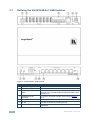
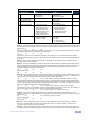
Defining the VS-801USB 8x1 USB Switcher
Figure 1: VS-801USB 8x1 USB Switcher
4
#
1
Feature
HOST USB (type B) Port
Function
2
DEVICE USB (type A) port Connects to a USB device (from 1 to 8)
3
REMOTE Switch Terminal
Block
Connect to contact closure switches for duplicating the
function of the front panel DEVICE SELECT buttons (see
Section 5.2)
4
ETHERNET RJ-45
Connector
Connect to a remote controller via a LAN (see Section
4.2)
5
RESET Button
Reset to the Ethernet factory default values
6
5V DC
+5V DC connector for powering the unit
7
IR Receiver
Receives signals from the infrared remote control
transmitter
Connects to the host
VS-801USB - Overview
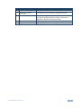
#
8
Feature
IR LED
Function
The yellow LED lights when receiving IR signals
9
RS-232 9-pin D-sub
Connector
Connects to a PC for firmware upgrade and control
10
PROG
Push in for “Program” using a small screwdriver to
upgrade to the latest Kramer firmware via RS-232, or
release for “Normal” (the factory default)
11
DEVICE SELECT Buttons
Select a device to switch to the host (from 1 to 8)
12
ON LED
Illuminates green when receiving power
VS-801USB - Overview
5
4
Connecting the VS-801USB
!
Always switch off the power to each device before connecting it to your
VS-801USB. After connecting your VS-801USB, connect its power
and then switch on the power to each device.
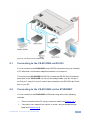
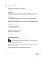
To connect the VS-801USB as illustrated in the example in Figure 2:
1. Connect the USB devices (for example, hard drives and/or memory sticks)
to the DEVICE ports. For example, a:
Hard drive to port 1
Memory stick to port 4
Hard drive to port 6
Memory stick to port 8
2. Connect the HOST USB port to an acceptor (for example, a laptop).
3. If required, you can connect a PC and/or controller to the:
i
RS-232 terminal block (see Section 4.1)
Ethernet connector (see Section 4.2)
For best results it is advised to use high quality USB cables
4. Connect the 5V DC power adapter to the power socket and connect the
adapter to the mains electricity (not shown in Figure 2).
6
VS-801USB - Connecting the VS-801USB
Figure 2: Connecting to the VS-801USB
4.1
Connecting to the VS-801USB via RS-232
You can connect to the VS-801USB via an RS-232 connection using, for example,
a PC. Note that a null-modem adapter/connection is not required.
To connect to the VS-801USB via RS-232, connect the RS-232 9-pin D-sub front
panel port on the VS-801USB unit via a 9-wire straight cable (only pin 2 to pin 2,
pin 3 to pin 3, and pin 5 to pin 5 need to be connected) to the RS-232 9-pin D-sub
port on your PC.
4.2
Connecting to the VS-801USB via the ETHERNET
You can connect to the VS-801USB via Ethernet using either of the following
methods:
•
•
Direct connection to the PC using a crossover cable (see Section 4.2.1)
Connection via a network hub, switch, or router, using a straight-through
cable (see Section 4.2.2)
VS-801USB - Connecting the VS-801USB
7
4.2.1
Connecting the ETHERNET Port Directly to a PC (Crossover Cable)
You can connect the Ethernet port of the VS-801USB to the Ethernet port on your
PC, via a crossover cable with RJ-45 connectors.
i
This type of connection is recommended for identifying the
VS-801USB with the factory configured default IP address.
After connecting the Ethernet port, configure your PC as follows:
1. Right-click the My Network Places icon on your desktop.
2. Select Properties.
3. Right-click Local Area Connection Properties.
4. Select Properties.
The Local Area Connection Properties window appears.
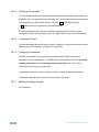
5. Select the Internet Protocol (TCP/IP) and click the Properties Button (see
Figure 3).
Figure 3: Local Area Connection Properties Window
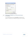
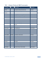
6. Select Use the following IP Address, and fill in the details as shown in
Figure 4.
7. Click OK.
8
VS-801USB - Connecting the VS-801USB
Figure 4: Internet Protocol (TCP/IP) Properties Window
4.2.2
Connecting the ETHERNET Port via a Network Hub (StraightThrough Cable)
You can connect the Ethernet port of the VS-801USB to the Ethernet port on a
network hub or network router, via a straight-through cable with RJ-45 connectors.
VS-801USB - Connecting the VS-801USB
9
5
Operating the VS-801USB
You can operate the VS-801USB via the front panel buttons (see Section 5.1), the
REMOTE contact closure terminal block connectors (see Section 5.2), the
application software (see Section 5.3) or the RC-IR3 IR remote control transmitter.
5.1
The Front Panel Buttons
To select a DEVICE to switch to the HOST, press one of the eight DEVICE
SELECT buttons.
5.2
The REMOTE Terminal Block Connector
The contact closure remote control pins operate in a similar way to the INPUT
SELECT button. Using the contact closure remote control (also known as push-tomake momentary contact) you can select the desired USB port. To do so,
momentarily connect the required DEVICE pin (from 1 to 8) on the REMOTE
terminal block connector to the G (Ground) pin, as Figure 5 illustrates.
!
Do not connect more than one PIN to the GND PIN at the same time.
Figure 5: Connecting the Contact Closure Remote Control PINs
5.3
The Application Software
Use the K-SINGLE control application software to control the VS-801USB via the
Ethernet or RS-232 9-pin D-sub.
i
10
The latest version of K-SINGLE and installation instructions can be
downloaded from the Kramer Web site at www.kramerelectronics.com
VS-801USB - Operating the VS-801USB
6
Firmware Upgrade
You can upgrade the VS-801USB via the Kramer K-UPLOAD software.
i
The latest version of K-UPLOAD and installation instructions, as well
as the application software and its user guide, can be downloaded
from the Kramer Web site at www.kramerelectronics.com
VS-801USB - Firmware Upgrade
11
7
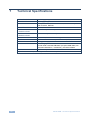
Technical Specifications
DEVICE PORTS:
8 x USB (type A) ports
HOST PORT:
1 USB (type B) port
CONTROL:
Front panel buttons, IR remote control, RS-232 on a 9-pin Dsub connector, Ethernet
POWER SOURCE:
5V DC, 150mA
OPERATING
TEMPERATURE:
0° to +55°C (32° to 131°F)
STORAGE
TEMPERATURE:
-45° to +72°C (-49° to 162°F)
HUMIDITY:
10% to 90%, RHL non-condensing
DIMENSIONS:
18.8cm x 11.4cm x 2.4cm (7.4" x 4.5" x 0.9") W, D, H
WEIGHT:
0.75kg (1.7lbs) approx.
ACCESSORIES:
Power supply, bracket installation kit
1 meter USB 2.0 A MALE/B MALE (Hi-speed USB cable, Rev
2 shielded 28AWG/1P + 24AWG/2C), P/N 2505-000005
OPTIONS:
19“ Rack adapter RK-T2B
Specifications are subject to change without notice at http://www.kramerelectronics.com
12
VS-801USB - Technical Specifications
8
Default Communication Parameters
RS-232
Protocol
3000 (Default)
2000
Baud Rate:
115,200
9,600
Data Bits:
8
8
Stop Bits:
1
1
Parity:
None
None
Command Format:
ASCII
ASCII
Example (Input 1 to Output 1):
#AV 1>1<CR>
0x01, 0x81, 0x81, 0x81
Switching Protocol
P2000 -> P3000
P3000 -> P2000
Command:
Command:
#P2000<CR>
Front Panel:
Press and hold DEVICE
SELECT buttons 1 and 2
simultaneously
0x38, 0x80, 0x83, 0x81
Front Panel: Press and hold DEVICE
SELECT buttons 1 and 3
simultaneously
Ethernet
IP Address:
192.168.1.39
Subnet mask:
255.255.255.0
Default gateway:
192.168.1.1
TCP Port #:
5000
UDP Port #:
50000
Maximum UDP Ports:
10
Maximum TCP Ports:
4
Factory Reset
RESET button
To reset the IP settings to the factory reset values, power cycle the device
while holding in the RESET button, located on the rear panel of the unit
Protocol 3000
Use “Factory” command or #Y 0,760,1<CR>
VS-801USB - Default Communication Parameters
13
9
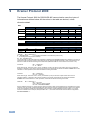
Kramer Protocol 2000
The Kramer Protocol 2000 for RS-232/RS-485 communication uses four bytes of
information as defined below. All the values in the table are decimal, unless
otherwise stated.
MSB
LSB
DESTINATION
INSTRUCTION
0
D
N5
N4
N3
N2
N1
N0
7
6
5
4
3
2
1
0
INPUT
I6
6
I5
5
I4
4
I3
3
I2
2
I1
1
I0
0
OUTPUT
O6
6
O5
5
O4
4
O3
3
O2
2
O1
1
O0
0
OVR
6
X
5
MACHINE NUMBER
M4
M3
4
3
M2
2
M1
1
M0
0
1st byte
1
7
2nd byte
1
7
3rd byte
1
7
4th byte
1st BYTE:
Bit 7 – Defined as 0.
D – “DESTINATION”:
0 - for sending information to the switchers (from the PC);
1 - for sending to the PC (from the switcher).
N5…N0 – “INSTRUCTION”
The function that is to be performed by the switcher(s) is defined by the INSTRUCTION (6 bits). Similarly, if a function is
performed via the machine’s keyboard, then these bits are set with the INSTRUCTION NO., which was performed. The
instruction codes are defined according to the table below (INSTRUCTION NO. is the value to be set for N5…N0).
2nd BYTE:
Bit 7 – Defined as 1.
I6…I0 – “INPUT”.
When switching (ie. instruction codes 1 and 2), the INPUT (7 bits) is set as the input number which is to be switched.
Similarly, if switching is done via the machine’s front-panel, then these bits are set with the INPUT NUMBER which was
switched. For other operations, these bits are defined according to the table.
3rd BYTE:
Bit 7 – Defined as 1.
O6…O0 – “OUTPUT”.
When switching (ie. instruction codes 1 and 2), the OUTPUT (7 bits) is set as the output number which is to be
switched. Similarly, if switching is done via the machine’s front-panel, then these bits are set with the OUTPUT
NUMBER which was switched. For other operations, these bits are defined according to the table.
4th BYTE:
Bit 7 – Defined as 1.
Bit 5 – Don’t care.
OVR – Machine number override.
M4…M0 – MACHINE NUMBER.
Used to address machines in a system via their machine numbers. When several machines are controlled from a single
serial port, they are usually configured together with each machine having an individual machine number. If the OVR bit
is set, then all machine numbers accept (implement) the command, and the addressed machine replies. For a single
machine controlled via the serial port, always set M4…M0 = 1, and make sure that the machine itself is configured as
MACHINE NUMBER = 1.
14
VS-801USB - Kramer Protocol 2000
Instruction Codes for Protocol 2000
Instruction
Definition for Specific Instruction
# Description
Input
Output
1
SWITCH VIDEO
5
56
REQUEST STATUS
OF A VIDEO OUTPUT
CHANGE TO ASCII
61
IDENTIFY MACHINE
62
DEFINE MACHINE
Set equal to video input which is
to be switched
(0 = disconnect)
Set as SETUP #
0
1 - video machine name
2 - audio machine name
3 - video software version
4 - audio software version
5 - RS422 controller name
6 - RS422 controller version
7 - remote control name
8 - remote software version
9 - Protocol 2000 revision
1 - number of inputs
2 - number of outputs
3 - number of setups
Notes
Set equal to video output which is
to be switched
(0 = to all the outputs)
Equal to output number whose
status is reqd
SVS protocol
Generic protocol
Protocol-3000
0 - Request first 4 digits
1 - Request first suffix
2 - Request second suffix
3 - Request third suffix
10 - Request first prefix
11 - Request second prefix
12 - Request third prefix
2, 15
1 - for video
2 - for audio
3 - for SDI
4 - for remote panel
5 - for RS-422 controller
14
4, 3
19
13
NOTES on the above table:
NOTE 2 - These are bi-directional definitions. That is, if the switcher receives the code, it performs the instruction; and if
the instruction is performed (due to a keystroke operation on the front panel), then these codes are sent. For example, if
the HEX code
01
85
88
83
was sent from the PC, then the switcher (machine 3) switches input 5 to output 8. If the user switched input 1 to output 7
via the front panel keypad, then the switcher sends HEX codes:
41
81
87
83
to the PC.
When the PC sends one of the commands in this group to the switcher, then, if the instruction is valid, the switcher
replies by sending to the PC the same four bytes that it was sent (except for the first byte, where the DESTINATION bit
is set high).
NOTE 3 - SETUP # 0 is the present setting. SETUP # 1 and higher are the settings saved in the switcher's memory,
(i.e. those used for Store and Recall).
NOTE 4 - The reply to a "REQUEST" instruction is as follows: the same instruction and INPUT codes as were sent are
returned, and the OUTPUT is assigned the value of the requested parameter. The replies to instructions 10 and 11 are
as per the definitions in instructions 7 and 8 respectively. For example, if the present status of machine number 5 is
breakaway setting, then the reply to the HEX code
0B
80
would be HEX codes
4B
80
80
85
81
85
NOTE 13 - This is a request to identify the switcher/s in the system. If the OUTPUT is set as 0, and the INPUT is set as
1, 2, 5 or 7, the machine sends its name. The reply is the decimal value of the INPUT and OUTPUT. For example, for a
2216, the reply to the request to send the audio machine name would be (HEX codes):
7D
96
90
81 (i.e. 128dec+ 22dec for 2nd byte, and 128dec+ 16dec for 3rd byte).
If the request for identification is sent with the INPUT set as 3 or 4, the appropriate machine sends its software version
number. Again, the reply would be the decimal value of the INPUT and OUTPUT - the INPUT representing the number
in front of the decimal point, and the OUTPUT representing the number after it. For example, for version 3.5, the reply to
the request to send the version number would be (HEX codes):
7D
83
85
81 (i.e. 128dec+ 3dec for 2nd byte, 128dec+ 5dec for 3rd byte).
If the OUTPUT is set as 1, then the ASCII coding of the lettering following the machine’s name is sent. For example, for
the VS-7588YC, the reply to the request to send the first suffix would be (HEX codes):
7D
D9
C3
81 (i.e. 128dec+ ASCII for “Y”; 128dec+ ASCII for “C”).
NOTE 14 - The number of inputs and outputs refers to the specific machine which is being addressed, not to the
system. For example, if six 16X16 matrices are configured to make a 48X32 system (48 inputs, 32 outputs), the reply to
the HEX code
3E
82
81
82 (ie. request the number of outputs)
would be HEX codes
7E
82
90
82
ie. 16 outputs
NOTE 15 – When the OVR bit (4th byte) is set, then the “video” commands have universal meaning. For example,
instruction 1 (SWITCH VIDEO) causes all units (including audio, data, etc.) to switch. Similarly, if a machine is in
“FOLLOW” mode, it performs any “video” instruction.
NOTE 19 – After this instruction is sent, the unit will respond to the ASCII command set defined by the OUTPUT byte.
The ASCII command to operate with the HEX command set must be sent in order to return to working with HEX codes.
VS-801USB - Kramer Protocol 2000
15
10
Protocol 3000
The VS-801USB can be operated using serial commands from a PC, remote
controller or touch screen using the Kramer Protocol 3000.
This section describes:
10.1
10.1.1
•
Kramer Protocol 3000 syntax (see Section 10.1)
•
Kramer Protocol 3000 commands (see Section 10.2)
Kramer Protocol 3000 Syntax
Host Message Format
Start
Address (optional)
Body
Delimiter
#
Destination_id@
Message
CR
10.1.1.1 Simple Command
Command string with only one command without addressing:
Start
Body
Delimiter
#
Command SP Parameter_1,Parameter_2,…
CR
10.1.1.2 Command String
Formal syntax with commands concatenation and addressing:
Start
Address
Body
Delimiter
#
Destination_id@
Command_1 Parameter1_1,Parameter1_2,…|
Command_2 Parameter2_1,Parameter2_2,…|
Command_3 Parameter3_1,Parameter3_2,…|…
CR
10.1.2
Device Message Format
Start
Address (optional)
Body
delimiter
~
Sender_id@
Message
CR LF
10.1.2.1 Device Long Response
Echoing command:
Start
Address (optional)
Body
Delimiter
~
Sender_id@
Command SP [Param1 ,Param2 …] result
CR LF
CR = Carriage return (ASCII 13 = 0x0D)
LF = Line feed (ASCII 10 = 0x0A)
SP = Space (ASCII 32 = 0x20)
16
VS-801USB - Protocol 3000
10.1.3
Command Terms
Command
A sequence of ASCII letters ('A'-'Z', 'a'-'z' and '-').
Command and parameters must be separated by at least one space.
Parameters
A sequence of alphanumeric ASCII characters ('0'-'9','A'-'Z','a'-'z' and some special
characters for specific commands). Parameters are separated by commas.
Message string
Every command entered as part of a message string begins with a message
starting character and ends with a message closing character.
Note: A string can contain more than one command. Commands are separated by
a pipe ( '|' ) character.
Message starting character
'#' – For host command/query
'~' – For device response
Device address (Optional, for K-NET)
K-NET Device ID followed by '@'
Query sign
'?' follows some commands to define a query request.
Message closing character
CR – For host messages; carriage return (ASCII 13)
CRLF – For device messages; carriage return (ASCII 13) + line-feed (ASCII 10)
Command chain separator character
When a message string contains more than one command, a pipe ( '|' ) character
separates each command.
Spaces between parameters or command terms are ignored.
VS-801USB - Protocol 3000
17
10.1.4
Entering Commands
You can directly enter all commands using a terminal with ASCII communications
software, such as HyperTerminal, Hercules, etc. Connect the terminal to the serial
or Ethernet port on the Kramer device. To enter CR press the Enter key.
( LF is also sent but is ignored by command parser).
For commands sent from some non-Kramer controllers like Crestron, some
characters require special coding (such as, /X##). Refer to the controller manual.
10.1.5
Command Forms
Some commands have short name syntax in addition to long name syntax to allow
faster typing. The response is always in long syntax.
10.1.6
Chaining Commands
Multiple commands can be chained in the same string. Each command is
delimited by a pipe character (“|”). When chaining commands, enter the message
starting character and the message closing character only once, at the
beginning of the string and at the end.
Commands in the string do not execute until the closing character is entered.
A separate response is sent for every command in the chain.
10.1.7
Maximum String Length
64 characters
18
VS-801USB - Protocol 3000
10.2
Kramer Protocol 3000 Commands
Command
Short
Form
Description
Permission
#
Protocol handshaking
End User
BAUD
Set protocol serial ports baud rate
Common
BAUD?
Get protocol serial ports baud rate
Common
BUILDDATE?
Read device build date
End User
ETH-PORT
ETHP
Change protocol Ethernet port
Administrator
ETH-PORT?
ETHP?
Get protocol Ethernet port
End User
FACTORY
Reset to factory default configuration
Administrator
HELP
List of commands
End User
LDFW
Load new firmware file
Administrator
MACH-NUM
Set machine number
End User
MODEL?
Read device model
End User
NAME
Set machine (DNS) name
Administrator
NAME?
Get machine (DNS) name
End User
NAME-RST
Reset machine (DNS) name to factory
default
Administrator
Administrator
NET-DHCP
NTDH
Set DHCP mode
NET-DHCP?
NTDH?
Get DHCP mode
End User
NET-GATE
NTGT
Set Gateway IP
Administrator
NET-GATE?
NTGT?
Get Gateway IP
End User
NET-IP
NTIP
Set device IP address
Administrator
NET-IP?
NTIP?
Get device IP address
End User
NET-MAC?
NTMC?
Get MAC address
End User
NET-MASK
NTMSK
Set device subnet mask
Administrator
NET-MASK?
NTMSK?
Get device subnet mask
End User
P2000
Switch to protocol 2000
End User
PASS
Set password
Administrator
PASS?
Get password
Administrator
PROT-VER?
Read device protocol version
End User
RESET
Reset device
Administrator
ROUTE
Set input
End User
ROUTE?
Get input
End User
SECURE
Start/Stop security
Administrator
SECURE?
Get current security state
Administrator
SN?
Read device serial number
End User
UPGRADE
Set device flag of new firmware
Administrator
VS-801USB - Protocol 3000
19
20
VS-801USB - Protocol 3000
For the latest information on our products and a list of Kramer distributors,
visit our Web site where updates to this user manual may be found.
We welcome your questions, comments, and feedback.
Web site: www.kramerelectronics.com
E-mail: [email protected]
!
SAFETY WARNING
Disconnect the unit from the power
supply before opening and servicing
P/N: 2900- 300030
Rev: 2