1
Configuration Guide
GS220
Table of Contents
Introduction
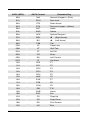
Bar Code Configuration Methods.............................................................. 1–1
Single-Code Method .............................................................................. 1–1
Multi-Code Method ................................................................................ 1–1
Need to Start Over? .................................................................................. 1–2
Code Types and Decode Rules
UPC/EAN.................................................................................................. 2–1
Code 128 .................................................................................................. 2–2
Code 39 .................................................................................................... 2–2
2 of 5 Codes ............................................................................................. 2–4
Codabar .................................................................................................... 2–6
Code 93 .................................................................................................... 2–6
Code 11 .................................................................................................... 2–6
Telepen..................................................................................................... 2–7
Plessey Codes .......................................................................................... 2–7
Additional Decode Features...................................................................... 2–8
Configurable Code Lengths ...................................................................... 2–9
Supplements ....................................................................................3–1
GS1 Databar .....................................................................................4–1
GS1 Databar Limited ................................................................................ 4–2
GS1 Databar Expanded............................................................................ 4–2
ISBT Code 128 Implementation
Configuration Mode .................................................................................. 5–1
Concatenation Configuration Mode .......................................................... 5–2
Pre-Defined Concatenation Configuration Mode ...................................... 5–2
User-Defined Concatenation Configuration Mode .................................... 5–3
i
Scanner Operation
Configuration Mode Options......................................................................6–1
Scan Buffers..............................................................................................6–1
Redundant Scans......................................................................................6–2
Miscellaneous Decode Features ...............................................................6–2
Same Symbol Timeouts ............................................................................6–3
LED Options ..............................................................................................6–3
Beeper Options .........................................................................................6–4
Data Transmission Delays.........................................................................6–6
Communication Timeout Options ..............................................................6–7
Host Scanner Commands .........................................................................6–8
Test Modes..............................................................................................6–10
Prefixes/Suffixes
User Configurable Prefixes, All Data .........................................................7–1
User Configurable ID Characters, Code Specific ...................................... 7–2
Standard Prefix Characters .......................................................................7–4
Standard Suffix Characters .......................................................................7–6
Longitudinal Redundancy Check...............................................................7–7
Block Check Character..............................................................................7–7
Character Replacements...........................................................................7–8
User Configurable Suffixes, All Data .........................................................7–9
Special Formats ......................................................................................7–10
Code Formatting
UPC/EAN Formatting ................................................................................8–1
Codabar Formatting ..................................................................................8–3
Code 39 Formatting...................................................................................8–4
Code 11 Formatting...................................................................................8–4
Telepen .....................................................................................................8–4
Plessey......................................................................................................8–5
2 of 5 Code Formatting.............................................................................. 8–5
ii
RS232
Parity Features ......................................................................................... 9–1
Baud Rate................................................................................................. 9–1
Data/Stop Bits........................................................................................... 9–2
Hardware Handshaking ............................................................................ 9–2
Software Handshaking.............................................................................. 9–4
Miscellaneous ........................................................................................... 9–5
Keyboard
Enable Keyboard Emulation ................................................................... 10–1
Country/Scan Code Table Selects.......................................................... 10–1
Keyboard/System Type........................................................................... 10–2
’Dumb’ Terminal Selections .................................................................... 10–3
Special Keyboard Features..................................................................... 10–4
InterScan Code Delays ........................................................................... 10–6
Control Sets ............................................................................................ 10–7
USB..................................................................................................11–1
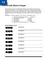
Code Bytes Usage
Code Bytes 0-9 ....................................................................................... 12–1
Reserved Codes ..................................................................................... 12–2
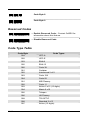
Code Type Table .................................................................................... 12–2
ASCII Reference Table ........................................................................... 12–3
Extended Key Code Reference Table .................................................... 12–7
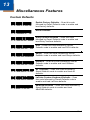
Miscellaneous Features
Custom Defaults......................................................................................13–1
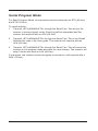
Serial Program Mode ..............................................................................13–2
Contact Information .......................................................................14–1
iii
vi
1
Introduction
Your new scanner has been factory configured with a set of default
parameters. Since many host systems have unique formats and protocol
requirements, GoDEX provides a wide range of configurable features that
may be selected using this bar code based configuration tool. Once the
configuration is completed, the scanner stores the settings in nonvolatile
memory (NOVRAM). NOVRAM saves the settings when the power is off.
Note: Bar code descriptions marked with an asterisk ( * ) define a feature that
is a factory default. Bar codes marked with a tilde ( ~ ) require the
Multi-Code configuration method.
Bar Code Configuration Methods
The GS220 scanner can be bar code configured in two ways: the Single-Code
Method and the Multi-Code Method.
Single-Code Method
Most features can be enabled or disabled using the Single-Code Method.
1.
Power-up the scanner.
2.
Scan the bar code for the desired feature.
3.
The scanner will emit a multi-toned beep to indicate the configuration
has been saved to NOVRAM.
Multi-Code Method
All features can be enabled or disabled using the Multi-Code Method.
A feature marked with a tilde ( ~ ) requires the Multi-Code Method.
1.
Power-up the scanner.
2.
Scan the enter/exit configuration mode bar code (3 beeps).
3.
Scan the bar code for the desired feature (1 beep). Multiple features
can be enabled/disabled before scanning the enter/exit configuration
mode bar code.
4.
Scan the enter/exit configuration mode bar code (3 beeps) and save
the new configuration. To abort a configuration change, power off the
scanner before scanning the enter/exit code.
Enter/Exit Configuration Mode
³
9
9
9
9
9
9
1–1
Need To Start Over?
Scan the Recall Defaults bar code to erase all previous settings and return
the scanner to its factory default communication protocol. Keyboard Wedge
interface scanners will load keyboard wedge defaults. All other scanners load
RS232 defaults.
Recall Defaults
³
1–2
9
9
9
9
9
8
2
Code Types and Decode Rules
Bar code descriptions marked with an asterisk ( * ) define a feature that is a
factory default. Bar codes marked with a tilde ( ~ ) require the Multi-Code
configuration method.
UPC/EAN
* Enable UPC/EAN
³
1
0
0
1
1
6
³
1
0
0
1
0
6
³
1
0
0
2
1
6
³
1
0
0
2
0
6
³
1
0
0
2
1
0
³
1
0
0
2
0
0
³
1
0
0
2
1
1
³
1
0
0
2
0
1
³
1
0
0
2
1
4
³
1
0
0
2
0
4
Disable UPC/EAN
* Enable UPC-A
Disable UPC-A
* Enable UPC-E
Disable UPC-E
* Enable EAN-13
Disable EAN-13
* Enable EAN-8
Disable EAN-8
2–1
Code 128
* Enable Code 128
³
1
0
0
1
1
3
³
1
0
0
1
0
3
³
1
0
0
3
1
4
³
1
0
0
3
0
4
³
1
0
0
7
1
1
³
1
0
0
7
0
1
Disable Code 128
Enable UCC/EAN-128 ‘]C1’ Code Formatting –
For Coupon Code 128, see page 3–3.
* Disable UCC/EAN-128 ‘]C1’ Code Formatting
Ignore <FNC4> Code 128 Characters
* Use <FNC4> to Determine Extended ASCII
Characters
Code 39
* Enable Code 39
³
1
0
0
1
1
1
³
1
0
0
1
0
1
³
1
0
0
2
1
3
³
1
0
0
2
0
3
³
1
0
0
2
1
7
³
1
0
0
2
0
7
Disable Code 39
Enable MOD 43 Check Digit on Code 39 – The
scanner only scans Code 39 bar codes that have
a valid Modulo 43 check digit.
* Disable MOD 43 Check Digit on Code 39
Enable Full ASCII Code 39
* Disable Full ASCII Code 39
2–2
³
1
0
0
2
1
5
³
1
0
0
2
0
5
³
1
0
0
3
0
7
³
1
0
0
3
1
7
³
1
0
0
3
1
2
³
1
0
0
3
0
2
³
1
0
0
7
0
2
³
1
0
0
7
1
2
³
1
0
0
4
1
6
³
1
0
0
4
0
6
³
1
0
0
9
1
4
³
1
0
0
9
0
4
³
1
0
7
7
1
5
³
1
0
7
7
0
5
Enable PARAF (Italian Pharmaceutical Codes)
Support – Code 39 bar codes are converted to
PARAF format.
* Disable PARAF Support
* Allow PARAF Codes Only
Allow Non-PARAF Codes
Enable TRI-OPTIC Code
* Disable TRI-OPTIC Code
* Use Standard Code 39 Framing
Try Code 39 Codes Without 5 Bar Multiples
Enable ITF/Code 39 Filters
* Disable ITF/Code 39 Filters
Enable Self-Service Library Code 39
* Disable Self-Service Library Code 39
Transmit MOD 43 Check Digit – with Self
Service Library Code 39
* Do Not Transmit MOD 43 Check Digit – with
Self Service Library Code 39
2–3
³
1
1
5
4
1
3
³
1
1
5
4
0
3
Enable Alternate Code 39 Reference
Comparison Check – assists with elements that
are below the 2 to 1 (wide to narrow) element
width requirement.
* Normal Code 39 Reference Comparison
Check
2 OF 5 CODES
* Enable Interleaved 2 of 5 (ITF)
³
1
0
0
1
1
5
³
1
0
0
1
0
5
³
1
0
0
3
1
0
³
1
0
0
3
0
0
³
1
0
7
8
1
7
³
1
0
7
8
0
7
³
9
0
1
6
0
0
³
9
0
1
7
0
0
³
9
0
3
4
0
0
Disable Interleaved 2 of 5 (ITF)
Enable MOD 10 Check on ITF – The scanner
will only scan Interleaved 2 of 5 (ITF) bar codes
that have a Modulo 10 check digit.
* Disable MOD 10 Check on ITF
Allow ITF Null Characters
* Do Not Allow ITF Null Characters
2–4
~ ITF Symbol Length Lock 1 – To specify a first
ITF symbol length lock, scan this bar code and
the appropriate code byte sequence located
on page 12–1.
~ ITF Symbol Length Lock 2 – To specify a second
ITF symbol length lock, scan this bar code and the
appropriate code byte sequence located
on page 12–1.
~ ITF Minimum Symbol Length – To specify a
minimum number of ITF characters to be decoded,
scan the appropriate code byte sequence located
on page 12–1.
Alternative ITF first Bar Reference
³
1
0
0
9
1
3
³
1
0
0
9
0
3
³
1
0
0
1
1
0
³
1
0
0
1
0
0
³
9
0
1
5
0
0
³
1
0
0
0
1
5
³
1
0
0
0
0
5
³
1
0
0
5
0
7
³
1
0
0
5
1
7
³
1
0
0
0
1
4
³
1
0
0
0
0
4
³
1
0
0
3
1
3
³
1
0
0
3
0
3
* Normal ITF first Bar Reference
Enable Standard 2 of 5
* Disable Standard 2 of 5
~ Standard 2 of 5 Symbol Length – To specify
the number of characters to be decoded, scan
this bar code and the appropriate code byte
sequence located on page 12–1.
Enable Matrix 2 of 5
* Disable Matrix 2 of 5
* Enable Matrix 2 of 5 Check Digit Requirement
Disable Matrix 2 of 5 Check Digit Requirement
Enable 15 Digit Airline 2 of 5
* Disable 15 Digit Airline 2 of 5
Enable 13 Digit Airline 2 of 5
* Disable 13 Digit Airline 2 of 5
2–5
Enable Hong Kong 2 of 5
³
1
0
0
3
1
6
³
1
0
0
3
0
6
³
1
1
5
4
1
1
³
1
1
5
4
0
1
* Disable Hong Kong 2 of 5
Enable Follett ITF
* Disable Follett ITF
Codabar
* Enable Codabar
³
1
0
0
1
1
4
³
1
0
0
1
0
4
³
1
0
0
0
1
2
³
1
0
0
0
0
2
Disable Codabar
Enable Dual Field Codabar
* Disable Dual Field Codabar
Code 93
* Enable Code 93
³
1
0
0
1
1
2
³
1
0
0
1
0
2
0
1
3
Disable Code 93
Code 11
Enable Code 11
³
2–6
1
0
0
* Disable Code 11
³
1
0
0
0
0
3
³
1
0
8
0
0
5
³
1
0
8
0
1
5
³
1
0
8
0
0
4
³
1
0
8
0
1
4
* Check for 1 Code 11 Check Digit
Check for 2 Code 11 Check Digits
* Do Not Check for 2 Code 11 Check Digits
Check for 2 Code 11 Check Digits if Code
Length is Greater Than 10 Characters
Telepen
Enable Telepen
³
1
0
0
0
1
7
³
1
0
0
0
0
7
³
1
0
0
0
1
6
³
1
0
0
0
0
6
* Disable Telepen
Enable ALPHA Telepen
* Disable ALPHA Telepen
Plessey Codes
Enable MSI Plessey
³
1
0
0
2
1
2
³
1
0
0
2
0
2
³
2
0
0
7
0
4
* Disable MSI Plessey
* No MSI Plessey Check Digit – Plessey bar
codes will not be tested for a check digit.
2–7
³
2
0
0
7
3
4
³
2
0
0
7
2
4
³
1
0
0
1
1
7
³
1
0
0
1
0
7
³
1
0
0
7
1
6
³
1
0
0
7
0
6
³
1
0
8
0
0
3
³
1
0
8
0
1
3
Enable MSI Plessey MOD 10/10 Check Digit –
Test MSI Plessey bar codes for a 2 digit
Modulo 10 check digit.
* Enable MSI Plessey MOD 10 Check Digit –
Test MSI Plessey bar codes for a 1 digit
Modulo 10 check digit.
Enable UK Plessey
* Disable UK Plessey
Enabled UK Plessey A to X Conversion
* Disabled UK Plessey A to X Conversion
* Standard Plessey Stop Characters
Accept Bad Plessey Stop Characters
Additional Decode Features
³
1
0
0
0
1
1
³
1
0
0
0
0
1
³
1
0
1
1
1
5
³
1
0
1
1
0
5
Enable Double Border Required / Large
Intercharacter Space
* Disable Double Border Required / Large
Intercharacter Space
Enable Small Border Required
* Disable Small Border
2–8
³
9
0
1
8
0
0
³
9
0
1
9
0
0
³
1
1
9
4
1
7
³
1
1
9
4
0
7
³
1
0
0
7
1
2
³
1
0
0
7
0
2
~ Minimum Symbol Length – Single-line default
is 3. Combine this code with the proper code bytes
(on page 12–1), to specify the minimum number
of characters in all non-UPC/EAN bar codes.
~ Symbol Length Lock – Combine this code with
the proper code bytes, to lock the bar code’s
length into place.
Enable Modulus 8 Filter on Bar & Space
Counts
* Disable Modulus 8 Filter on Bar & Space
Counts
Handle Code 39 Bad Border
* Disable Code 39 Bad Border
Configurable Code Lengths
There are seven bar code lock lengths available. Specific code types can be
assigned to a lock length.
While in configuration mode:
1. Scan the code length lock #1 bar code (below).
2. Scan the three code bytes that represent the code length
(on page 12–1).
3. Scan the matching code type lock #1 bar code (below).
4. Scan the three code bytes that represent the code type (on page 12–1).
This process can be repeated for lock lengths 2 through 7.
~ Code Length Lock #1
³
9
0
2
0
0
0
³
9
0
2
1
0
0
~ Code Type Lock #1
2–9
~ Code Length Lock #2
³
9
0
2
2
0
0
³
9
0
2
3
0
0
³
9
0
2
4
0
0
³
9
0
2
5
0
0
³
9
0
2
6
0
0
³
9
0
2
7
0
0
³
9
0
2
8
0
0
³
9
0
2
9
0
0
³
9
0
3
0
0
0
³
9
0
3
1
0
0
³
9
0
3
2
0
0
³
9
0
3
3
0
0
³
1
2
4
7
1
3
³
1
2
4
7
0
3
~ Code Type Lock #2
~ Code Length Lock #3
~ Code Type Lock #3
~ Code Length Lock #4
~ Code Type Lock #4
~ Code Length Lock #5
~ Code Type Lock #5
~ Code Length Lock #6
~ Code Type Lock #6
~ Code Length Lock #7.
~ Code Type Lock #7.
Enable Japanese Multi-Field
Disable Japanese Multi-Field
2–10
3
Supplements
Enable Two Digit Supplements
³
1
0
1
2
1
7
³
1
0
1
2
0
7
³
1
0
1
2
1
2
³
1
0
1
2
0
2
³
1
0
1
2
1
6
³
1
0
1
2
0
6
³
1
0
1
2
1
1
³
1
0
1
2
0
1
³
1
0
1
2
1
3
³
1
0
1
2
0
3
³
1
0
1
4
1
6
³
1
0
1
4
0
6
³
1
2
5
1
1
4
³
1
2
5
1
0
4
* Disable Two Digit Supplements
* Enable Two Digit Redundancies – The scanner
will scan the bar code plus the 2 digit add on
twice before accepting data.
Disable Two Digit Redundancies
Enable Five Digit Supplements
* Disable Five Digit Supplements
Enable Five Digit Redundancies – The scanner
will scan the bar code plus the 5 digit add on
twice before accepting data.
* Disable Five Digit Redundancies
Supplements are Required – All UPC/EAN
labels that are scanned must have a supplement.
* Supplements are Not Required
Enable Remote Supplement Required
* Disable Remote Supplement Required
Enable Bookland (979) Supplement Required
* Disable Bookland (979) Supplement Required
3–1
Enable Bookland (978) Supplement Required
³
1
0
1
4
1
7
³
1
0
1
4
0
7
³
1
0
1
3
1
4
³
1
0
1
3
0
4
³
1
0
1
3
1
3
³
1
0
1
3
0
3
³
1
0
1
4
1
3
³
1
0
1
4
0
3
³
1
0
1
4
1
5
³
1
0
1
4
0
5
³
1
0
1
4
1
2
³
1
0
1
4
0
2
³
1
0
1
2
1
5
³
1
0
1
2
0
5
* Disable Bookland (978) Supplement Required
Enable 977 (2 Digit) Supplement Required –
The scanner will require a 2 digit supplement to be
scanned when an EAN-13 code begins with 977.
* Disable 977 (2 Digit) Supplement Required
Enable 378/379 French Supplement Required
* Disable 378/379 French Supplement Required
Enable 414/419 German Bookland
Supplement Required
* Disable 414/419 German Bookland
Supplement Required
Enable 434/439 German Supplement Required
* Disable 434/439 German Supplement
Required
Enable # System 2 Requires Supplements
* Disable # System 2 Requires Supplements
3–2
Enable UPC # System 5 Requires
Supplements
* Disable UPC # System 5 Requires
Supplements
* Enable 2 Digit Supplements with 37x, 43x, or
UPC # System 5
³
1
0
1
0
0
0
³
1
0
1
0
1
0
³
1
0
1
0
0
1
³
1
0
1
0
1
1
³
1
0
0
3
1
5
³
1
0
0
3
0
5
³
1
0
1
4
1
1
³
1
0
1
4
0
1
³
1
0
1
4
1
4
³
1
0
1
4
0
4
³
3
0
1
3
4
0
400 msec to Find Supplemental – The scanner
will allot 400 milliseconds to find an add on after
a main UPC/EAN bar code has been scanned.
³
3
0
1
3
2
0
200 msec to Find Supplemental – The scanner
will allot 200 milliseconds to find an add on after
a main UPC/EAN bar code has been scanned.
³
3
0
1
3
1
0
* 100 msec to Find Supplemental – The scanner
will allot 100 milliseconds to find an add on after
a main UPC/EAN bar code has been scanned.
Disable 2 Digit Supplements with 37x, 43x, or
UPC # System 5
* Enable 5 Digit Supplements with 37x, 43x, or
UPC # System 5
Disable 5 Digit Supplements with 37x, 43x, or
UPC # System 5
Enable Coupon Code 128
* Disable Coupon Code 128
Enable Code 128 ‘]C1’ Extended Code Format
–The scanner transmits a ‘]C1’ at the beginning
of the Code 128 portion of the coupon code.
* Disable Code 128 ‘]C1’ Extended Code
Format.
* Enable Code 128 Group Separators – A “GS”
(1DH) character will be transmitted with coupon
Code 128 codes.
Disable Code 128 Group Separators
3–3
Enable Code ID’s with Supplements
³
1
0
1
2
1
4
³
1
0
1
2
0
4
³
1
1
8
4
0
6
³
1
1
8
4
1
6
³
1
0
1
3
1
5
³
1
0
1
3
0
5
³
1
0
1
3
1
7
³
1
0
1
3
0
7
³
1
0
1
3
1
6
³
1
0
1
3
0
6
³
1
2
5
1
1
5
³
1
2
5
1
0
5
³
1
2
5
1
0
6
³
1
2
5
1
1
6
* Disable Code ID’s with Supplements
* Beep Once on Supplements
Beep Twice on Supplements
Enable ISBN Check Digit Transmission – Not
available with all models.
Disable ISBN Check Digit Transmission
Enable Bookland to ISBN Conversion – Not
available with all models.
* Disable Bookland to ISBN Conversion
Enable ISBN Re-Formatting
* Disable ISBN Re-Formatting
Enable Bookland to ISBN 979 Conversion
* Disable Bookland to ISBN 979 Conversion
* Normal ISBN Re-Formatting
13 Digit ISBN Re-Formatting
3–4
³
1
2
5
0
1
7
³
1
2
5
0
0
7
No Supplement Checking if EAN-13 Code is
just scanned
* Normal Supplement Checking
3–5
3–6
4
GS1 Databar
GoDEX’s GS220 scanners with software #14810 and higher can be
configured to scan GS1 Databar type bar codes.
³
1
0
0
0
1
1
³
1
0
0
4
1
3
³
1
0
0
4
0
3
³
1
1
4
9
0
0
³
1
1
4
9
1
0
³
1
1
4
9
0
1
³
1
1
4
9
1
1
³
1
1
4
9
0
2
³
1
1
4
9
1
2
Double Border Required – Due to the large
spaces commonly found in GS1 Databar
symbologies, GoDEX recommends double
border requirements be enabled when scanning
GS1 Databar code type symbologies.
Enable GS1 Databar 14
* Disable GS1 Databar 14
* Transmit GS1 Databar 14 Check Digit
Do Not Transmit GS1 Databar 14 Check Digit
* Transmit GS1 Databar 14 Application ID –
Application Identifier “01” is transmitted
by default.
Do Not Transmit GS1 Databar 14
Application ID
* Transmit GS1 Databar 14 Symbology ID –
Symbology Identifier “]e0” is transmitted
by default.
Do Not Transmit GS1 Databar 14 Symbology
4–1
GS1 Databar Limited
Enable GS1 Databar Limited
³
1
0
0
4
1
4
³
1
0
0
4
0
4
³
1
1
4
9
0
3
³
1
1
4
9
1
3
³
1
1
4
9
0
4
³
1
1
4
9
1
4
³
1
1
4
9
0
5
³
1
1
4
9
1
5
* Disable GS1 Databar Limited
* Transmit GS1 Databar Limited CD
Do Not Transmit GS1 Databar Limited CD
* Transmit GS1 Databar Limited Application ID –
Application identifier “01” is transmitted by default.
Do Not Transmit GS1 Databar Limited
Application ID
* Transmit GS1 Databar Limited Symbology ID –
Symbology identifier “]e0” is transmitted by default.
Do Not Transmit GS1 Databar Limited
Symbology ID
GS1 Databar Expanded
Enable GS1 Databar Expanded
³
1
0
0
4
1
5
³
1
0
0
4
0
5
³
1
1
4
9
0
6
³
1
1
4
9
1
6
* Disable GS1 Databar Expanded
4–2
* Transmit GS1 Databar Expanded Symbol ID –
Symbology identifier “]e0” is transmitted by default.
Do Not Transmit GS1 Databar Expanded
Symbol ID
5
ISBT Code 128 Implementation
Configuration Mode
³
1
3
8
4
1
7
³
1
3
8
4
0
7
Enable ISBT Code 128
Disable ISBT Code 128
The bar codes below enable or disable a special transmit mode as outlined in
section 3.5.2 of the ISBT-128 Specification. This output method allows the user
to confirm independently the accuracy of the Code-128 check digit.
³
1
3
8
4
1
6
³
1
3
8
4
0
6
Enable ISBT Special Transmit
Disable ISBT Special Transmit
The bar codes below enable or disable the transmission of the ISBT Code 128
data identifiers. When this option is enabled, the first two data characters
are removed from the data stream (ID characters) unless the ISBT bar code
scanned contains Donation Identification Number identifiers. If Donation
Identification Number identifiers are present, only the first ID character is
removed from the Donation ID Number. The second is regarded as
normal data.
³
1
3
8
4
1
5
³
1
3
8
4
0
5
Don’t Transmit ISBT ID’s
* Transmit ISBT Identifiers
The bar codes below convert and transmit the Mode 37, 2 check digit from the
flag digits of the Donation Identification Number provided the check digit is
contained in the flag digits. Transmission of the Donation Identification number
will be the same except for the last two digits, which are converted into a single
check sum character.
³
1
3
8
5
1
0
³
1
3
8
5
0
0
Convert Flag Digits to Mod 37, 2 CD
* Normal Flag Digit Transmission
5–1
Concatenation Configuration Mode
The following bar codes are used to configure variable time requirements used
to find the second bar code of the ISBT concatenation sequence.
³
3
0
1
3
1
0
³
3
0
1
3
2
0
³
3
0
1
3
3
0
³
3
0
1
3
4
0
³
3
0
1
3
5
0
³
3
0
1
3
6
0
³
3
0
1
3
7
0
100 msec to Find Concatenation Sequence
200 msec to Find Concatenation Sequence
300 msec to Find Concatenation Sequence
400 msec to Find Concatenation Sequence
500 msec to Find Concatenation Sequence
600 msec to Find Concatenation, Sequence
700 msec to Find Concatenation Sequence
Pre-Defined Concatenation Configuration Mode †
The first two bar codes below enable or disable pre-defined concatenation
sequences. The remaining bar codes enable the specific pre-defined
concatenation sequence shown, but are not needed to enable concatenation.
They can be used to disable or re-enable any selected pre-defined
concatenation sequence.
³
1
3
8
4
1
3
³
1
3
8
4
0
3
³
4
3
8
4
8
0
5–2
Enable Pre-Defined Concatenation Sequence
Disable Pre-Defined Concatenation Sequence
Donation Identification Number + AB0/Rh (D)
Blood Groups =á + =% Concatenation
Donation Identification Number + Donor
Identification Number =á + &; Concatenation
³
4
3
8
4
9
0
³
4
3
8
4
1
0
0
Donation Identification Number + Confidential
Unit Exclusion Status =á + &! Concatenation
³
4
3
8
4
1
1
0
Product Code + Expiration Date (Form 1)
=< + =>Concatenation
³
4
3
8
4
1
2
0
Product Code + Expiration Date (Form 2)
=< + &> Concatenation
³
4
3
8
4
1
3
0
Product Code + Expiration Date (Form 3)
&< + => Concatenation
³
4
3
8
4
1
4
0
Product Code + Expiration Date (Form 4)
&< + &> Concatenation
User-Defined Concatenation Configuration Mode
The first two bar codes shown below can be used to enable or disable userdefined concatenation sequences. The remaining bar codes are used to enter
the user-defined identifiers used in the concatenation sequence. First enter
configuration mode then scan the one of the identifier codes, followed by the
code byte sequence or the desired identifiers.
³
1
3
8
4
1
4
³
1
3
8
4
0
4
³
9
3
8
0
0
0
³
9
3
8
1
0
0
³
9
3
8
2
0
0
³
9
3
8
3
0
0
Enable User-Defined Sequences
Disable User-Defined Sequences
st
1 Left Identifier
nd
2
Left Identifier
st
1 Right Identifier
2nd Right Identifier
5–3
The following example demonstrates how to configure the User-Defined ISBT
identifiers:
Assume the left-hand identifiers are the ISBT defined donation
identification number: “=G”; and the right hand identifiers are country
specific identifiers “&a”.
1.
2.
3.
4.
5.
6.
7.
8.
9.
10.
11.
12.
Scan the ENTER/EXIT configuration mode bar code.
st
Scan the 1 Left Identifier configuration mode bar code.
Scan (Code Byte 0) + (Code Byte 6) + (Code Byte 1).
Scan the 2nd Left Identifier configuration mode bar code.
Scan (Code Byte 0) + (Code Byte 7) + (Code Byte 1).
Scan the 1st Right Identifier configuration mode bar code.
Scan (Code Byte 0) + (Code Byte 3) + (Code Byte 8).
Scan the 2nd Right Identifier configuration mode bar code.
Scan (Code Byte 0) + (Code Byte 9) + (Code Byte 7).
Scan the Enable User-Defined Sequence bar Code.
Scan the Enable ISBT bar code.
Scan the ENTER/EXIT configuration mode bar code.
The scanner is now configured with the appropriate identifiers. Since both
ISBT and User-defined Concatenation are enabled, ISBT 128 bar codes
scanned successively that contain these identifiers will be concatenated.
An alternate method of the type found in section 4.8.1 of the ISBT
specifications can be used for configuring user-defined concatenation
sequences. Using the previous example, the identifiers can be configured into
a single configuration mode bar code. The following bar codes can be used to
enable and disable the user-defined concatenation.
Enable (Left, =G) + (Right, &a)
=
&
³
=
G
&
a
5
0
5
d
1
Disable (Left, =G) + (Right, &a)
=
&
³
=
G
&
a
5
0
5
d
0
Note: These configuration bar codes require Single-Code configuration mode.
These bar codes are not recognized in Multi-Code configuration mode.
Two forms of concatenation can be enabled at any given time, one pre-defined
sequence and the user-defined sequence. Code selects and ISBT Code-128
concatenation cannot be used simultaneously. Both functions use the same
internal resources so they must remain mutually exclusive.
5–4
6
6
Scanner Operation
Configuration Mode Options
³
1
1
8
1
1
7
³
1
1
8
1
0
7
³
1
1
8
1
1
6
³
1
1
8
1
0
6
Allow Configuration Mode on Power Up – the
scanner can only enter Configuration mode before
any bar codes are scanned.
* Allow Configuration Mode Anytime – Allow the
configuration at any time.
Allow configuration Codes on Power Up –
Once a product bar code is scanned after powerup, the scanner will not accept configuration bar
codes.
* Allow Configuration Codes Anytime – Allows
scanning of configuration bar codes at any time.
Scan Buffers
* 1 Scan Buffer – The scanner will scan one bar
code in the scan field and not scan again until
the bar code is removed from the scan field for
the duration of the same symbol time out.
³
3
1
8
0
0
0
³
3
1
8
0
1
0
³
3
1
8
0
2
0
3 Scan Buffers – Same function as 2 Scan
Buffers, but three bar codes are in the scan field.
³
3
1
8
0
3
0
4 Scan Buffers – Same function as 2 Scan
Buffers, but four bar codes are in the scan field.
2 Scan Buffers – The scanner will scan two bar
codes in the scan field one time each. These two
bar codes will not be scanned again and until
they are removed from the scan field for the
duration of the same symbol time out.
6–1
Redundant Scans
* 0 Redundant Scans – Requires 1 good decode
for a good scan.
³
3
0
1
1
0
0
³
3
0
1
1
1
0
1 Redundant Scan – Requires 2 consecutive
decodes of the same bar code data for a good
scan.
³
3
0
1
1
2
0
2 Redundant Scans – Requires 3 consecutive
decodes of the same bar code data for a good
scan.
³
3
0
1
1
3
0
3 Redundant Scans – Requires 4 consecutive
decodes of the same bar code data for a good
scan.
³
3
0
1
1
4
0
4 Redundant Scans – Requires 5 consecutive
decodes of the same bar code for a good scan.
³
3
0
1
1
5
0
5 Redundant Scans – Requires 6 consecutive
decodes of the same bar code for a good scan.
³
3
0
1
1
6
0
³
3
0
1
1
7
0
6 Redundant Scans – Requires 7 consecutive
decodes of the same bar code for a good scan.
7 Redundant Scans – Requires 8 consecutive
decodes of the same bar code for a good scan.
Miscellaneous Decode Features
³
1
1
8
1
1
3
³
1
1
8
1
0
3
6–2
* Optional Same Symbol Check – Requires 1
different character between successive bar
codes to consider the bar code new.
Normal Same Symbol Check – Requires 3
different characters between successive bar
codes to consider the bar code new.
LED Options
³
1
1
8
3
1
3
³
1
1
8
3
0
3
³
1
1
8
3
1
2
³
1
1
8
3
0
2
Flash Green LED if Rescan Allowed – This
indicates same symbol timeout has elapsed.
Do Not Flash Green LED if Rescan Allowed
Reverse LED Functions – Red = Laser On
Green = Good Read
* Normal LED Functions – Green = Laser On
Red = Good Read
6–3
Beeper Options
* Normal Tone
³
3
1
8
5
7
5
³
3
1
8
5
6
5
³
3
1
8
5
5
5
³
3
1
8
5
4
5
³
3
1
8
5
3
5
³
3
1
8
5
2
5
³
3
1
8
5
1
5
³
3
1
8
5
0
5
³
1
1
8
4
0
6
³
1
1
8
4
1
6
³
1
1
8
4
1
4
³
1
1
8
4
0
4
³
1
1
8
5
1
2
³
1
1
8
5
0
2
Optional Tone 1
Optional Tone 2
Optional Tone 3
Optional Tone 4
Optional Tone 5
Optional Tone 6
No Beep
* Beep Once on Supplements
Beep Twice on Supplements
Enable Fast Beep
* Disable Fast Beep
Enable Fun Tones – scan this bar code then
scan one of the Optional Tone bar codes above.
* Disable Fun Tones
6–4
³
1
1
8
4
1
7
³
1
1
8
4
0
7
³
1
1
6
9
1
3
³
1
1
6
9
0
3
³
1
2
4
7
1
1
³
1
2
4
7
0
1
³
1
2
5
0
1
1
³
1
2
5
0
0
1
³
1
2
5
0
1
0
³
1
2
5
0
0
0
³
9
9
8
0
5
2
Beep on BEL Command – The scanner beeps
when it receives a BEL character from the host. If
a number is sent within 200 msecs before the
BEL character, the scanner will beep that
number of times.
* Ignore BEL Command
Enable Light Pen Toggle During Beep –
The scanner beeps and toggles the light pen
data line on a successful decode. This drives a
good read indicator.
* Disable Light Pen Toggle During Beep
Enable Pass-Through
Disable Pass-Through
Beep with Pass-Through Data
* No Beep with Pass-Through Data
Enable Record Count Capture
* No Record Count Capture
Transmit Record Counts
6–5
Data Transmission Delays
Use these codes to select the amount of delay between sending data
characters from the scanner to the host. This helps prevent the scanner from
overflowing host-input buffers.
* 1 msec Intercharacter Delay
³
8
1
8
8
1
0
³
8
1
8
8
1
0
0
³
8
1
8
8
2
5
0
³
9
1
8
8
0
0
³
8
1
8
8
0
0
³
9
1
9
3
0
0
³
1
1
9
3
1
7
³
1
1
9
3
0
7
10 msec Intercharacter Delay
25 msec Intercharacter Delay
~ Variable msec Intercharacter Delay – Scan this
bar code and a sequence of code bytes on page
12–1 to set the delay between characters sent to
the host system (range from 1 to 255 msecs.).
No Intercharacter Delay
~ Variable Inter-Record Delay
Turn Off Laser During Inter-Record Delay
* Leave Laser On During Inter-Record Delay
6–6
Communication Time Out Options
Enable Communications Time Out
³
1
1
8
4
1
2
³
1
1
8
4
0
2
³
1
1
8
4
1
3
³
1
1
8
4
0
3
³
9
1
9
1
0
0
³
8
1
9
1
4
0
0
³
8
1
9
1
2
0
0
³
8
1
9
1
8
0
0
³
1
1
8
4
1
0
³
1
1
8
4
0
0
³
1
1
8
4
1
1
³
1
1
8
4
0
1
* Disable Communications Time Out
* Beep Before Transmit
Beep After Transmit
~ Variable Communications Time Out
* Default Communications Time Out (2 secs)
Short Communications Time Out (1 secs)
Long Communications Time Out (4 secs)
Three Beeps on Time Out
* No Beeps on Time Out
Razzberry Tone on Time Out
* No Razzberry Tone on Time Out
6–7
Host Scanner Commands
³
1
1
8
0
1
5
³
1
1
8
0
0
5
³
1
1
8
2
1
1
³
1
1
8
2
0
1
³
1
1
8
0
1
4
³
1
1
8
0
0
4
³
1
1
8
1
1
5
³
1
1
8
1
0
5
³
1
1
8
1
1
0
³
1
1
8
1
0
0
Enable D/E Disable Command – The scanner
will disable scanning after it receives an ASCII
“D” from the host device. It will enable scanning
when it receives an ASCII “E”.
* Disable D/E Disable.
Enable Z/R Type D/E Simulation – The scanner
will disable scanning after it receives an ASCII
“Z” from the host device. It will enable scanning
when it receives an ASCII “R”.
* No Z/R Type D/E Simulation
Enable F/L Laser Command – The scanner will
turn off the laser after the scanner receives an
ASCII “F” character. The laser will turn on after it
receives an ASCII “L” character.
* Disable F/L Laser Command
Use DTR Scan Disable – The scanner will
monitor the DTR input to determine if scanning
should be allowed. A +12V active level enables
decoding. A -12V inactive level disables decoding.
* Do Not Use DTR Scan Disable – Do not monitor
the DTR input.
Activate DC2 Character – Scanning will be
initiated with the receipt of a DC2 character
(^R, 124).
* Do Not Activate on DC2 Character
6–8
³
1
1
5
9
1
6
³
1
1
5
9
0
6
³
1
1
8
1
1
1
³
1
1
8
1
0
1
³
1
1
8
3
1
1
³
1
1
8
3
0
1
³
9
9
9
9
6
9
³
1
1
8
2
1
3
³
1
1
8
2
0
3
³
1
2
5
0
1
6
³
1
2
5
0
0
6
³
1
2
5
0
1
3
³
1
2
5
0
0
3
Transmit Scanner ID byte with receipt of an
“i” (69H) via RS232 – The ID byte is transmitted
as 3 bytes (i.e. 0, 0, 1).
* Don’t Transmit Scanner ID byte with receipt
of an “i” (69H) via RS232
Transmit NO READ if DC2 Activated
* Do Not Transmit NO READ if DC2 Activated
No Green LED During NO READ Transmit
* Green LED During NO READ Transmit
Transmit Serial Number
Enable Motor On/Off Commands
* Disable Motor On/Off Commands
Disable RS232 Receive
Normal RS232 Receive
Enable Banco Control Mode
Disable Banco Control Mode
6–9
³
1
4
1
7
1
5
³
1
4
1
7
0
5
³
1
1
9
9
1
7
³
1
1
9
9
0
7
Use Protocol Prefix and Suffix for Bar Code
Transmission
* No Protocol Prefix and Suffix for Bar Code
Transmission
Enable RTS on No Read – After a NOREAD
occurs, the scanner will activate the RTS line for
20 milliseconds. The duration of the RTS
activation can be loaded in address 199 bits 6–0
in 10 millisecond steps.
* Disable RTS on No Read
Test Modes
³
1
1
8
0
1
6
³
1
1
8
0
0
6
³
1
1
5
5
1
2
³
1
1
5
5
0
2
Scan Count Mode ON – The scanner will enter
scan count test mode and the scanner’s firmware
number will transmit to the host. Do not enable
unless instructed by a GoDEX representative.
* Scan Count Mode OFF
6–10
Power-Up with Saved Interface – Do not
enable unless instructed by a GoDEX
representative.
* Power-Up with Board Interface – Do not enable
unless instructed by a GoDEX representative.
7
77
Prefixes/Suffixes
Scan the Enter Configuration Mode bar code before trying to set these features
(see the Multi-Code Method on page 1–1).
User Configurable Prefixes, All Data
~ Configurable Prefix Character #1 – A prefix ID
can be added and assigned for data transmission.
Use this code with a code byte sequence, on page
12–1, which represents the desired character.
³
9
0
3
5
0
0
³
9
0
3
6
0
0
~ Configurable Prefix Character #2 – Assigns a
second configurable prefix character.
³
9
0
3
7
0
0
~ Configurable Prefix Character #3 – Assigns a
third configurable prefix character.
³
9
0
3
8
0
0
~ Configurable Prefix Character #4 – Assigns a
fourth configurable prefix character.
³
9
0
3
9
0
0
~ Configurable Prefix Character #5 – Assigns a
fifth configurable prefix character.
³
9
0
4
0
0
0
~ Configurable Prefix Character #6 – Assigns a
sixth configurable prefix character.
³
9
0
4
1
0
0
~ Configurable Prefix Character #7 – Assigns a
seventh configurable prefix character.
³
9
0
4
2
0
0
~ Configurable Prefix #8 – Assigns an eighth
configurable prefix character.
³
9
0
4
3
0
0
~ Configurable Prefix Character #9 – Assigns a
ninth configurable prefix character.
³
9
0
4
4
0
0
~ Configurable Prefix Character #10 – Assigns a
tenth configurable prefix character.
³
9
9
9
9
8
5
* Clear All User Configurable Prefixes
7–1
User Configurable ID Characters, Code Specific
³
1
0
5
5
0
7
³
1
0
5
5
1
7
* Use Configurable Code ID Bytes as Prefixes –
User configured, code specific ID bytes are
transmitted before the data. If using prefixes,
user configured suffixes can not be used.
Use Configurable Code ID Bytes as Suffixes –
User configured, code specific ID bytes are
transmitted after the data. If using suffixes, user
configured prefixes can not be used.
‡ Enter configuration mode then scan this bar code followed by the three
code byte bar codes (on page 12–1) that represent a unique ID character to
be associated with this bar code type.
~ Configurable UPC-A ID ‡
³
9
0
5
6
0
0
³
9
0
5
7
0
0
³
9
0
5
8
0
0
³
9
0
5
9
0
0
³
9
0
6
0
0
0
³
9
0
6
1
0
0
³
9
0
6
3
0
0
³
9
0
6
4
0
0
³
9
0
6
2
0
0
~ Configurable UPC-E ID ‡
~ Configurable EAN-8 ID ‡
~ Configurable EAN-13 ID ‡
~ Configurable Code 39 ID ‡
~ Configurable Code 128 ID ‡
~ Configurable Code 93 ID ‡
~ Configurable Code 11 ID ‡
~ Configurable Telepen ID ‡
7–2
‡
Enter configuration mode then scan this bar code followed by the three
code byte bar codes (on page 12–1) that represent a unique ID character
to be associated with this bar code type.
~ Configurable TRI-OPTIC ID ‡
³
9
0
7
2
0
0
³
9
0
7
1
0
0
³
9
0
6
7
0
0
³
9
0
6
8
0
0
³
9
0
6
9
0
0
³
9
0
6
5
0
0
³
9
0
7
0
0
0
³
9
0
6
6
0
0
³
9
9
9
9
8
3
³
1
0
5
5
1
6
³
1
0
5
5
0
6
³
1
2
4
7
1
6
³
1
2
4
7
0
6
~ Configurable Standard 2 of 5 ID ‡
~ Configurable Interleaved 2 of 5 ID ‡
~ Configurable Matrix 2 of 5 ID ‡
~ Configurable Airline 2 of 5 ID ‡
~ Configurable MSI Plessey ID ‡
~ Configurable UK Plessey ID ‡
~ Configurable Codabar ID ‡
* Clear All Configurable Code Specific ID’s –
Clears all unique ID characters previously
identified.
Enable Teraoka ID
* Disable Teraoka ID
Enable Taiwan 7-11 ID
* Disable Taiwan 7-11 ID
7–3
Standard Prefix Characters
³
1
1
6
6
1
5
³
1
1
6
6
0
5
³
1
0
5
5
1
3
³
1
0
5
5
0
3
³
1
0
7
9
1
5
³
1
0
7
9
0
5
³
1
1
6
6
1
7
³
1
1
6
6
0
7
³
1
0
7
9
1
1
³
1
0
7
9
0
1
³
9
4
1
5
0
0
³
1
0
7
9
1
7
³
1
0
7
9
0
7
Enable STX Prefix – The scanner will transmit a
Start of TeXt (ASCII 02H) before each bar code.
* Disable STX Prefix
Enable Rochford-Thomson Mode
* Disable Rochford-Thomson Mode
Enable AIM ID Characters
* Disable AIM ID Characters
Enable UPC Prefix ID – A prefix will be
transmited before any UPC/EAN code. The
prefixes are A (UPC-A), E0 (UPC-E), F (EAN-13),
and FF (EAN-8).
* Disable UPC Prefix ID.
Enable NCR Prefix ID – A prefix will be
transmitted before the following code types. The
prefixes are as follows: A (UPC-A), E0 (UPC-E),
FF (EAN-8), F (EAN 13), B1 (Code 39) B2 (ITF),
B3 (Code 128 and other codes).
* Disable NCR Prefix ID
Enable NCR Prefix Character
Enable Nixdorf ID Characters – This option
transmits code identities before each bar code
for many Siemen/Nixdorf registers.
* Disable Nixdorf ID Characters
7–4
Enable SANYO ID Characters
³
1
0
7
9
1
6
³
1
0
7
9
0
6
³
1
0
5
5
1
2
³
1
0
5
5
0
2
³
1
0
5
5
1
1
³
1
0
5
5
0
1
³
1
0
5
5
1
0
³
1
0
5
5
0
0
³
1
1
6
6
1
1
³
1
1
6
6
0
1
³
1
1
6
1
1
1
³
1
1
6
1
0
1
³
1
1
6
1
1
3
³
1
1
6
1
0
3
* Disable SANYO ID Characters
Enable Manufacturer ID Prefix
* Disable Manufacturer ID Prefix
Enable “C” Prefix
* Disable “C” Prefix
Enable “$” Prefix ID for UPC/EAN
* Disable “$” Prefix ID for UPC/EAN
Enable Tab Prefix – The scanner will transmit a
TAB (ASCII 09H) before each bar code.
* Disable Tab Prefix
Enable SNI Beetle Mode
* Disable SNI Beetle Mode
Enable Cipher 1021 IDs
* Disable Cipher 1021 IDs
7–5
Standard Suffix Characters
* Enable CR Suffix – The scanner transmits a
³
1
1
6
6
1
3
³
1
1
6
6
0
3
³
1
1
6
6
1
2
³
1
1
6
6
0
2
³
1
1
6
6
1
0
³
1
1
6
6
0
0
³
1
1
6
6
1
4
³
1
1
6
6
0
4
³
1
1
6
6
1
6
³
1
1
6
6
0
6
³
9
4
1
6
0
0
³
1
2
4
6
1
0
³
1
2
4
6
0
0
carriage return after each bar code.
Disable CR Suffix.
* Enable LF Suffix – The scanner transmits a line
feed after each bar code. Disabled when
keyboard wedge defaults are loaded.
Disable LF Suffix.
Enable Tab Suffix – The scanner will transmit a
TAB (ASCII 09H) after each bar code.
* Disable Tab Suffix
Enable ETX Suffix – The scanner will transmit
End of TeXt (ASCII 03H) after the bar code date.
* Disable ETX Suffix
Enable UPC Suffix ID – The scanner will
transmit a suffix after any UPC/EAN bar code.
The suffixes are A (UPC-A), E (UPC-E),
F (EAN-13) and F (EAN-8).
* Disable UPC Suffix ID
Enable NCR Suffix Character
Enable Tec 7-11 IDs
* Disable Tec 7-11 IDs
7–6
Longitudinal Redundancy Check
A Longitudinal Redundancy Check (LRC) is an error checking character that is
calculated across a sequence of data characters. It is determined by eXclusive
ORing (XOR) the characters to be checked, starting with an initial value of
00H.
The result, an “LRC byte” is then transmitted following the data stream and
used by the receiving computer to determine if the information was received
correctly. In the scanner’s case, XOR is performed prior to adding parity bits.
When the LRC is enabled, the scanner defaults to starting the LRC on the
second byte of information transmitted. Optionally, the calculation can start on
the first byte transmitted.
³
1
0
7
8
1
1
³
1
0
7
8
0
1
³
1
0
7
8
0
0
³
1
0
7
8
1
0
Enable Transmit of LRC Calculation – The
scanner outputs on LRC check character after
the bar code.
* Disable Transmit of LRC Calculation.
* Start LRC on First Byte – The scanner will
calculate the LRC check digit starting with the
first character.
Start LRC on Second Byte – The scanner will
calculate the LRC check digit starting with the
second character.
Block Check Character
* Enable NCR BCC
³
1
4
1
4
0
0
³
1
4
1
4
1
0
Disable NCR BCC
7–7
Character Replacements
To replace a character:
1.
Scan the enter/exit configuration mode bar code (on page 1–1).
2.
Scan the character to replace code (shown below).
3.
Scan the ASCII code byte value of the character you wish to replace.
Refer to the ASCII Reference Table in the Code Byte Usage section of
this manual.
4.
Scan the replacement character bar code (shown below).
5.
Scan the ASCII code byte value of the replacement character.
6.
Scan the enter/exit configuration mode bar code (on page 1–1).
~ Character to Replace
³
9
3
8
6
0
0
³
9
3
8
7
0
0
³
8
3
8
6
0
0
~ Replacement Character
No Replacement
7–8
User Configurable Suffixes, All Data
Note: Scan the Enter/Exit Configuration mode code before trying to set this
feature. Refer to Multi-Code Method on page 1–1.
~ Configurable Suffix Character #1 – A suffix ID
can be added and assigned for data
transmission. Use this code with a 3 code byte
sequence, on page 12–1, which represents the
desired character.
³
9
0
4
5
0
0
³
9
0
4
6
0
0
~ Configurable Suffix Character #2 – Assigns a
second configurable suffix character.
³
9
0
4
7
0
0
~ Configurable Suffix Character #3 – Assigns a
third configurable suffix character.
³
9
0
4
8
0
0
~ Configurable Suffix Character #4 – Assigns a
fourth configurable suffix character.
³
9
0
4
9
0
0
~ Configurable Suffix Character #5 – Assigns a
fifth configurable suffix character.
³
9
0
5
0
0
0
~ Configurable Suffix Character #6 – Assigns a
sixth configurable suffix character.
³
9
0
5
1
0
0
~ Configurable Suffix Character #7 – Assigns a
seventh configurable suffix character.
³
9
0
5
2
0
0
~ Configured Suffix Character #8 – Assigns an
eighth configurable suffix character.
³
9
0
5
3
0
0
~ Configurable Suffix Character #9 – Assigns a
ninth configurable suffix character.
³
9
0
5
4
0
0
~ Configurable Suffix Character #10 – Assigns a
tenth configurable suffix character.
³
9
9
9
9
8
4
* Clear All User Configurable Suffixes
7–9
Special Formats
Enable SINEKO Mode
³
1
0
7
9
1
4
³
1
0
7
9
0
4
³
1
1
6
7
1
1
³
1
1
6
7
0
1
³
1
1
6
7
1
0
³
1
1
6
7
0
0
³
1
0
8
0
1
7
³
1
0
8
0
0
7
³
1
1
6
7
1
3
³
1
1
6
7
0
3
³
1
2
4
7
1
5
³
1
2
4
7
0
5
* Disable SINEKO Mode
Enable Newcode Formatting Mode A
* Disable Newcode Formatting Mode A
Enable Newcode Formatting Mode B
* Disable Newcode Formatting Mode B
Remove All Leading Zero’s
* Do Not Remove Leading Zero’s
Enable MS951 CAPS Lock
* Disable MS951 CAPS Lock
Enable HCA Parsing
Disable HCA Parsing
7–10
8
88
Code Formatting
UPC/EAN Formatting
* Transmit UPC-A Check Digit
³
1
0
7
5
1
7
³
1
0
7
5
0
7
³
1
0
7
5
1
6
³
1
0
7
5
0
6
³
1
0
7
5
1
5
³
1
0
7
5
0
5
³
1
0
7
6
0
2
³
1
0
7
6
1
2
³
1
0
7
5
1
0
³
1
0
7
5
0
0
³
1
0
7
5
1
4
³
1
0
7
5
0
4
Do Not Transmit UPC-A Check Digit
Transmit UPC-E Check Digit
* Do Not Transmit UPC-E Check Digit
Expand UPC-E to 12 Digits – Expand UPC-E bar
codes to the 12 digit equivalent, UPC-A bar codes.
* Do Not Expand UPC-E to 12 Digits
* Send Number System on Expanded UPC E
Do Not Send Number System on Expanded
UPC E
Enable GTIN Formatting
* Disable GTIN Formatting
Convert UPC-A to EAN-13 – The scanner
converts UPC-A to EAN-13 by transmitting a
leading zero before the bar code.
* Do Not Convert UPC-A to EAN-13
8–1
³
1
0
7
5
1
3
³
1
0
7
5
0
3
³
1
0
7
5
1
2
³
1
0
7
5
0
2
³
1
0
7
5
1
1
³
1
0
7
5
0
1
³
1
0
7
6
1
1
³
1
0
7
6
0
1
³
1
0
7
6
1
0
³
1
0
7
6
0
0
³
1
0
7
9
1
0
³
1
0
7
9
0
0
³
1
0
7
9
1
2
³
1
0
7
9
0
2
Transmit Lead Zero on UPC-E – This option will
transmit a zero before each UPC-E bar code.
Do Not Transmit Lead Zero on UPC-E
Convert EAN-8 to EAN-13 – The scanner will
transmit five zeros before the bar code to convert
EAN-8 to EAN-13.
* Do Not Convert EAN-8 to EAN-13
* Transmit UPC-A Number System
Do Not Transmit UPC-A Number System
* Transmit UPC-A MFR #
Do Not Transmit UPC-A MFR #
* Transmit UPC-A ITEM #
Do Not Transmit UPC-A ITEM #
* Transmit EAN-8 Check Digit
Do Not Transmit EAN-8 Check Digit
* Transmit EAN-13 Check Digits – The scanner
will transmit EAN-13 Check Digit.
Do Not Transmit EAN-13 Check Digit.
8–2
Codabar Formatting
³
1
0
7
7
1
7
³
1
0
7
7
0
7
³
1
1
5
1
0
0
³
1
1
5
1
1
0
³
1
0
7
7
1
6
³
1
0
7
7
0
6
³
1
0
0
4
1
0
³
1
0
0
4
0
0
³
1
0
0
4
1
1
³
1
0
0
4
0
1
³
1
0
8
0
0
6
³
1
0
8
0
1
6
Transmit Codabar Start/Stop Characters –
Transmits Codabar’s Start/stop characters before
and after each bar code.
* Do Not Transmit Codabar Start/Stop
* Normal Codabar Start/Stop Characters
Enable Transmit Codabar Start/Stop
Characters as Lower Case Characters
Enable CLSI Editing – Works only with 14 digit
Codabar type lengths. This option will perform
CLSI type editing before the information is
transmitted to the host.
* Do Not Enable CLSI Editing
Enable Codabar Mod-16 Check Digit
* Disable Codabar Mod-16 Check Digit
Enable Codabar “7-Check” Check Digit
* Disable Codabar “7-Check” Check Digit
* Transmit Codabar Check Digit
Don’t Transmit Codabar Check Digit
8–3
Code 39 Formatting
³
1
0
7
7
1
5
³
1
0
7
7
0
5
³
1
0
7
7
1
0
³
1
0
7
7
0
0
³
1
0
7
7
1
2
³
1
0
7
7
0
2
Transmit Mod 43 Check Digit on Code 39 –
This feature works in conjunction with Mod 43
Check Digit on Code 39 option, on page 2–2.
Both must be enabled for this feature to work.
* Do Not Transmit Mod 43 Check Digit on
Code 39
Transmit Code 39 Stop/Start Characters –
The scanner transmits Code 39’s start and stop
characters before and after each bar code.
* Do Not Transmit Code 39 Stop/Start
Characters
Transmit an “A” (41H) Prefix if Italian
Pharmaceutical
* Do not Transmit an “A” (41H) Prefix if Italian
Pharmaceutical
Code 11 Formatting
³
1
0
7
7
1
3
³
1
0
7
7
0
3
Transmit Code 11 Check Digit – This bar code
will transmit Code 11 check characters when
used with Enabled Code 11 on page 2–6.
* Do Not Transmit Code 11 Check Digit
Telepen
Enable Convert Telepen ^L to E
³
1
0
7
8
1
4
³
1
0
7
8
0
4
* Disable Convert Telepen ^L to E
8–4
Plessey
³
1
0
7
8
1
6
³
1
0
7
8
0
6
³
1
0
7
8
1
5
³
1
0
7
8
0
5
³
1
0
7
7
1
1
³
1
0
7
7
0
1
Transmit UK Plessey Check Digit – The scanner
will transmit UK Plessey Check Digit characters
and must be used with the UK Plessey option.
* Do Not Transmit UK Plessey Check Digit
Enable UK Plessey Special Format
Disable UK Plessey Special Format
Transmit MSI Plessey Check Digit – This option
works in conjunction with one or both of the
Enabled MSI Plessey Mod options on page 2–7.
* Do Not Transmit MSI Plessey Check Digit
2 of 5 Code Formatting
³
1
0
7
7
1
4
³
1
0
7
7
0
4
³
1
0
7
8
1
2
³
1
0
7
8
0
2
Transmit Mod 10 Check Digit on ITF – The
scanner transmits interleaved 2 of 5 (ITF) Mod 10
check character.
* Do Not Transmit Mod 10 Check Digit on ITF –
Works in conjunction with Mod 10 check on ITF.
Both must be enabled for this feature to work.
Transmit Matrix 2 of 5 Check Digit
* Do Not Transmit Matrix 2 of 5 Check Digit
8–5
8–6
9
99
³
RS232
4
1
5
5
5
* Enable RS232 Mode – the scanner will work
with RS232 +/-12V serial output.
4
Parity Features
A parity bit is an extra data bit used to help catch data transmission errors.
The scanner’s parity must match the host’s parity.
No Parity
³
3
1
6
0
4
5
³
3
1
6
0
0
5
³
3
1
6
0
1
5
³
3
1
6
0
2
5
Even Parity – Select to set the parity bit to either
a 1 or 0 to ensure an even number of bits are 1s.
³
3
1
6
0
3
5
Mark Parity – Select Mark Parity to set the parity
bit always to 1.
Odd Parity – Select to set the parity bit to either a
1 or a 0 to ensure an odd number of bits are 1s.
* Space Parity – Select to set the parity bit
always to 0.
Baud Rate
³
4
1
5
8
1
0
0
³
4
1
5
8
9
0
³
4
1
5
8
8
0
³
4
1
5
8
7
0
³
4
1
5
8
6
0
115200 BAUD Rate
(Not available with Voyager)
57600 BAUD Rate
(Not available with Voyager)
38400 BAUD Rate
19200 BAUD Rate
14400 BAUD Rate
9–1
* 9600 BAUD Rate
³
4
1
5
8
5
0
³
4
1
5
8
4
0
³
4
1
5
8
3
0
³
4
1
5
8
2
0
³
4
1
5
8
1
0
³
4
1
5
8
0
0
4800 BAUD Rate
2400 BAUD Rate
1200 BAUD Rate
600 BAUD Rate
300 BAUD Rate
Data/Stop Bits
³
1
1
6
0
1
3
³
1
1
6
0
0
3
³
1
1
6
0
1
4
³
1
1
6
0
0
4
8 Data Bits – The number of data bits
transmitted for each character.
* 7 Data Bits
1 Stop Bit
* 2 Stop Bits
Hardware Handshaking
³
1
1
5
8
1
6
³
1
1
5
8
0
6
Enable RTS/CTS Handshaking – Output a
Request to Send (RTS) signal and wait for a Clear
to Send (CTS) signal before transmitting data.
* Disable RTS/CTS Handshaking.
9–2
* Character RTS/CTS – Activates/Deactivates
RTS signal for each character.
³
1
1
5
8
1
5
³
1
1
5
8
0
5
³
1
2
4
5
1
0
³
1
2
4
5
0
0
³
1
2
4
5
1
1
³
1
2
4
5
0
1
³
1
2
4
5
1
2
³
1
2
4
5
0
2
* Activate RTS, Wait for CTS – Wait for CTS after
activating RTS.
³
1
2
4
5
1
3
Test CTS Not Present Before RTS (RSV4) – Do
not activate RTS if CTS is already present.
³
1
2
4
5
0
3
³
1
1
5
8
1
7
³
1
1
5
8
0
7
Message RTS/CTS – Activates RTS before
sending the first character and leaves it active
until after the last character has been
transmitted.
Invert RTS Polarity (RSV1)
-12V = Active
+12V = Inactive
* Standard RTS Polarity – Use standard RTS
polarity
-12V = Inactive
+12V = Active
Invert CTS Polarity (RSV2)
-12V = Active,
+12V = Inactive,
OK to send
Do not send
* Standard CTS Polarity
-12V = Inactive,
Do not send
+12V = Active,
OK to send
Activate RTS, Do Not Wait for CTS (RSV3) –
Activate RTS for transmission but do not wait for
CTS to send.
* Do Not Test for CTS Present Before RTS
Enable DTR Support – The scanner will stop
scanning when the Data Terminal Ready (DTR)
signal goes inactive.
* Disable DTR Support
9–3
³
1
1
5
9
1
5
³
1
1
5
9
0
5
³
1
1
5
9
1
4
³
1
1
5
9
0
4
Enable RTS Counter Toggle – The scanner will
toggle the RTS line on a good decode.
* Disable RTS Counter Toggle
Enable XON/XOFF Handshaking – The scanner
will stop transmission whenever on XOFF
(ASCII 13H) is received. Transmission will
resume after an XON (ASCII 11H) is received.
* Disable XON/XOFF Handshaking.
Software Handshaking
³
1
1
5
9
1
3
³
1
1
5
9
0
3
³
1
1
5
9
1
1
³
1
1
5
9
0
1
³
1
1
8
0
1
3
³
1
1
8
0
0
3
Enable ACK/NAK – After transmitting data, wait
for an ACK (06H) or a NAK (15H) response from
the host. If ACK is received, complete the
communications cycle and look for more bar
codes. If NAK is received, retransmit the last set
of bar code data and wait for ACK/NAK again.
* Disable ACK/NAK
Support BEL/CAN in ACK/NAK – When BEL
(07H) is received, the scanner beeps 3 times and
exits the communications loop. If a CAN (18H) is
received, then the scanner will exit the
communications loop, silently.
* Ignore BEL/CAN in ACK/NAK – Ignore
BEL/CAN characters in communication loop.
Enable 5 Retries on ACK/NAK Time Out –
Allow up to 5 NAK retransmissions of the data
before dropping out of the communications loop.
* Disable 5 Retries on ACK/NAK Time Out
9–4
³
1
1
5
8
1
4
³
1
1
5
8
0
4
³
1
2
5
2
1
0
³
1
2
5
2
0
0
Enable 5 NAK Retries
Allow up to 5 retransmissions of the data if a
NAK is received.
* Disable 5 NAK Retries
Enable GLS Handshaking – Accept ]V for the
ACK acknowledgement. ACK will no longer be
accepted but NAK and any additional ACK/NAK
protocol characters enabled are still accepted.
* Disable GLS Handshaking
Miscellaneous
³
1
1
6
1
1
0
³
1
1
6
1
0
0
³
1
4
1
4
1
6
³
1
4
1
4
0
6
Enable French PC Term – The scanner
transmits PC type make/break scan codes
instead of ASCII data characters. The scan
codes match a WYSE French PC Term.
* Disable French PC Term
Enable NCR Scanner – Only Commands
* Disable NCR Scanner – Only Commands
9–5
9–6
10
Keyboard
Enable Keyboard Emulation
Load Keyboard Wedge Defaults – Loads the
default settings for keyboard wedge mode.
³
9
9
9
9
9
4
³
5
1
5
5
1
5
3
³
5
1
5
5
1
4
3
Enable Stand-Alone Keyboard Emulation –
Use this with special stand-alone models that are
not cabled for an external keyboard. Scan this
bar code to enable the Stand-Alone Mode. The
scanner will send keyboard “power on”
information and configure hardware to simulate a
constant keyboard connection.
* Enable Keyboard Wedge Emulation – Use this
with an external keyboard. Transmit in wedge
made to allow standard PC keyboards to
communicate when no bar code data is
available.
Country/Scan Code Table Selects
* USA Keyboard
³
4
1
6
2
6
0
³
4
1
6
2
8
0
³
4
1
6
2
5
0
³
4
1
6
2
4
0
³
4
1
6
2
3
0
³
4
1
6
2
2
0
³
4
1
6
2
1
0
Switzerland Keyboard
Spain Keyboard
Italy Keyboard
Germany Keyboard
France Keyboard
UK Keyboard
10–1
Belgium Keyboard
³
4
1
6
2
0
0
³
4
1
6
2
1
³
4
1
6
2
7
0
³
4
1
6
2
9
0
³
4
1
Japan Keyboard
0
0
IBM 4700 Financial Keyboard
Sweden/Finland Keyboard
Slovenian Keyboard
6
2
1
1
0
Keyboard/System Type
* AT Keyboard – Includes IBM PS/2 and
compatible models 50, 55, 60, 80.
³
2
1
6
2
1
5
³
2
1
6
2
0
5
³
2
1
6
2
2
5
³
2
1
6
2
3
5
³
1
1
6
3
0
7
Enable XT Keyboard for Mode 1 – Special
firmware in Voyager.
³
1
1
6
3
1
7
Enable XT Keyboard for Mode 2 – Special
firmware in Voyager.
XT Keyboard – Special firmware in Voyager.
PS/2 Keyboard – Includes IBM PC and
compatible models 30, 70, 8556.
Enable Terminal Keyboard Emulation.
10–2
‘Dumb’ Terminal Selections
Note: The following terminals may require custom cables.
IBM Terminal Keyboards
³
3
1
6
4
0
0
³
3
1
6
4
1
0
³
3
1
6
4
2
0
³
3
1
6
4
3
0
³
3
1
6
4
4
0
³
3
1
6
4
5
0
³
3
1
6
4
6
0
³
3
1
6
4
7
0
³
1
1
6
7
1
4
³
1
1
6
7
0
4
³
1
1
6
7
1
5
³
1
1
6
7
0
5
Reserved Terminal Keyboard #2
Reserved Terminal Keyboard #3
Reserved Terminal Keyboard #4
Reserved Terminal Keyboard #5
Reserved Terminal Keyboard #6
Reserved Terminal Keyboard #7
Reserved Terminal Keyboard #8
Lower Case Lock On – transmit all data as
lower case.
* Lower Case Lock Off
Spanish Keyboard Ñ Substitution – the
following two characters will translate as follows:
# to Ñ and ^ to ñ.
* No Spanish Keyboard Ñ Substitution
10–3
Special Keyboard Features
Transmit Make Code Only – Not available on
all models.
³
1
1
6
3
1
1
³
1
1
6
3
0
1
* Transmit Make/Break Code – Not available on
all models.
³
1
1
6
3
1
0
* Transmit FOH Break Code – The scanner will
transmit the FOH in the break-code sequence.
³
1
1
6
3
0
0
³
1
1
6
3
1
5
³
1
1
6
3
0
5
³
1
1
6
2
1
7
³
1
1
6
2
0
7
Do Not Transmit FOH Break Code
Transmit Cleanup Bit – Use for certain NEC
computers.
* Do Not Transmit Cleanup Bit
Enable Alt-Mode – See Enable ALT-Mode
(Normal) for description.
* Disable Alt-Mode – Caution: If host software
application uses the right Alt key as a “Hot” key,
Alt-mode must be disabled.
† These settings only apply if the Alt-Mode (shown above) is enabled.
†
³
1
1
6
7
0
6
* Enable Alt-Mode (Normal)
The scanner will duplicate the following keyboard
sequence; Hold down the Alt key and Type the
three digit decimal number that corresponds to
the appropriate character.
†
³
10–4
1
1
6
7
1
6
Enable Alt-Mode (Advanced)
The scanner will duplicate the following keyboard
sequence; Hold down the Alt key and Type the
four digit decimal number that corresponds to the
appropriate character.
³
1
1
6
2
1
4
³
1
1
6
2
0
4
³
1
1
6
2
1
4
³
1
1
6
2
0
4
³
1
1
6
3
1
6
³
1
1
6
3
0
6
³
1
1
6
4
1
0
³
1
1
6
4
0
0
³
1
1
6
3
0
3
³
1
1
6
3
1
3
³
1
1
6
3
0
4
³
1
1
6
3
1
4
Enable Auto Detect Mode (AT/PS2) –
Automatically detects caps lock status.
* Disable Auto Detect Mode (AT/PS2)
Enable Caps Lock (XT)
* Disable Caps Lock (XT)
Send Numbers as Keypad Data – All data is
sent as if it has been entered on a keypad.
* Send Numbers as Normal Data
Enable Reserved Feature
* Disable Reserved Feature
* Use Extended ASCII To Send Extended Key
Codes – Use extended ASCII characters to send
PC keyboard keys e.g., F1, F2.
Use Extended ASCII Characters as Extended
ASCII> – Transmit extended ASCII codes via
Alt Mode.
* Character KB Inhibit
Message KB Inhibit
10–5
Enable Right Alt Key Sequencing
³
1
1
6
3
0
2
³
1
1
6
3
1
2
³
1
1
6
4
1
3
³
1
1
6
4
0
3
Disable Right Alt Key Sequencing
Enable LaCaixa Special Keyboard Prefix &
Suffix Scan Codes
* Disable LaCaixa Special Keyboard Prefix &
Suffix Scan Codes
InterScan Code Delays
³
8
1
³
8
1
³
8
³
10–6
9
1
6
6
6
1
5
5
5
6
8
7
1
5
5
5
0
* InterScan Code Delay 800 msec – The time
specified represents the amount of time between
individual 11-bit scan codes. This parameter may
need to be adjusted for operation with certain PC
keyboard BIOS.
0
0
0
0
0
InterScan Code Delay 7.5 msec – This time
specified represents the amount of time between
individual 9-bit scan codes. This parameter may
need to be adjusted for operation with certain PC
keyboard BIOS.
InterScan Code Delay 15 msec – The time
specified represents the amount of time between
individual 11-bit scan codes. This parameter may
need to be adjusted for operation with certain PC
keyboard BIOS.
~ Variable InterScan Code Delay msec – Refer
to Multi-Code Method on page 1–1. Sets value in
100 microsecond increments.
Control Sets
In general, standard bar code symbologies will only encode the ASCII
character set. Function keys, arrow keys and many other extended keys on an
IBM compatible keyboard do not translate to ASCII characters. One method of
‘bar coding’ the extended keys is to substitute the extended key codes when a
specific ASCII control character is found in the bar code stream. The Control
Sets are specific translations of the ASCII (HEX) set.
Control Set #1
Enable Control Set #1
³
4
1
6
4
8
4
³
4
1
6
4
0
4
* Disable Control Set #1
10–7
ASCII (HEX)
ASCII Control
00H
Null
Numeric Keypad + (Plus)
01H
SOH
Num Lock
10–8
Extended Key
02H
STX
Down Arrow
03H
ETX
Numeric Keypad - (Minus)
04H
EOT
Insert
05h
ENQ
Delete
06H
ACK
System Request
07H
BEL
(Right Arrow)
08H
BS
(Left Arrow)
09H
TAB
0AH
LF
Tab
Caps Lock
0BH
VT
Shift Tab
0CH
FF
Left Alt
0DH
CR
Enter
0EH
SO
Left Control
OFH
SI
Up Arrow
10H
DLE
F1
11H
DC1
F2
12H
DC2
F3
13H
DC3
F4
14H
DC4
F5
15H
NAK
F6
16H
SYN
F7
17H
ETB
F8
18H
CAN
F9
19H
EM
F10
1AH
SUB
Home
1BH
ESC
1CH
FS
Page Up
Esc
1DH
GS
Page Down
1EH
RS
Print Screen
1FH
US
End
11
USB
Enable USB Interface♦
³
4
1
5
5
1
³
9
9
9
9
7
1
4
Enable Low Speed USB Defaults♦
8
♦ This feature is limited to GoDEX scanners without integrated Low Speed
USB electronics.
³
9
9
9
9
4
0
Load Integrated Full Speed USB Keyboard
Emulation Defaults
³
9
9
9
9
7
0
Load Integrated Full Speed USB IBM/OEM
Defaults
³
9
9
9
9
3
1
³
3
1
6
4
3
0
³
3
1
³
3
1
6
4
0
1
Load Integrated Low Speed USB OPOS Defaults
Feature is limited to scanners with internal
Low-Speed USB interfaces with specific software
versions.
IBM OEM Scanner 4B00h Hand-Held – Full
Speed USB Only
0
IBM OEM Scanner 4A00h Flat-Bed – Full
Speed USB Only
* Enable USB Keyboard Emulation Mode
6
4
0
0
Note: USB Keyboard Emulation Mode is a factory default. If the Recall
Defaults bar code is scanned while reconfiguring the scanner, the
scanner configuration will revert to the factory default setting
discarding any previous configuration settings for USB Serial
Emulation.
11–1
Enable Bar Code ID
³
1
1
7
8
1
7
³
1
1
7
8
0
7
³
1
1
9
8
1
7
³
1
1
9
8
0
7
³
9
9
9
9
7
3
³
9
9
9
9
7
2
³
9
9
9
9
6
7
³
9
9
9
9
6
6
³
1
1
7
8
1
3
³
1
1
7
8
0
3
Disable Bar Code ID
Enable USB Reserve Code #1
Disable USB Reserve Code #1
Enable USB Reserve Code #2
Disable USB Reserve Code #2
Sears USB Defaults
Sears Aux Defaults
Enable IBM 1520 Code Flag Emulation –
UPC code IDs and ITF code IDs remain the
same but all other code IDs are transmitted as
Code 39 (IBM OEM Scanner Modes).
Disable IBM 1520 Code Flag Emulation
11–2
12
Code Bytes Usage
The scanner must be in Configuration Mode for the features requiring code
bytes for configuration. The Enter/Exit Configuration Mode bar code must be
scanned before starting the configuration cycle. User configurable prefix/suffix
characters can then be saved by scanning the 3 digit decimal equivalent of the
ASCII character into the appropriate character location with the code byte bar
codes.
Example: To add an Asterisk (*) as a Prefix, scan the bar codes.
1.
2.
3.
4.
5.
6.
Enter/Exit Configuration Mode
(3 beeps)
Configurable Prefix #1
(1 beep)
Code Byte 0
(1 beep)
Code Byte 4
(2 beeps)
Code Byte 2
(3 beeps)
Enter/Exit Configuration Mode
(3 beeps)
Code Bytes 0–9
Code Byte 0
³
0
³
1
³
2
³
3
³
4
³
5
³
6
³
7
Code Byte 1
Code Byte 2
Code Byte 3
Code Byte 4
Code Byte 5
Code Byte 6
Code Byte 7
12–1
Code Byte 8
³
8
³
9
Code Byte 9
Reserved Codes
³
9
9
9
9
8
8
³
9
9
9
9
8
7
~ Enable Reserved Code – Contact GoDEX for
information about this feature.
~ Disable Reserved Code
Code Type Table
Code Byte
004
12–2
Code Types
UPC-A
002
UPC-E
003
EAN-8
005
EAN-13
080
Code 39
081
Codabar
082
Interleaved 2 of 5
083
Code 128
084
Code 93
091
MSI Plessey
092
Code 11
093
Airline 2 of 5 (15 digits)
094
Matrix 2 of 5
095
Telepen
096
UK Plessey
099
TRI-OPTIC
098
Standard 2 of 5
097
Airline (13 digits)
ASCII Reference Table
HEX Value
Decimal Value/
Code Byte Value
Character
Control
Keyboard Eqv
00
000
NUL
@
01
001
SOH
A
02
002
STX
B
03
003
ETX
C
04
004
EOT
D
05
005
ENQ
E
06
006
ACK
F
07
007
BEL
G
08
008
BS
H
09
009
HT
I
0A
010
LF
J
0B
011
VT
K
0C
012
FF
L
0D
013
CR
M
0E
014
SO
N
0F
015
SI
0
10
016
DLE
P
11
017
DC1
Q
12
018
DC2
R
13
019
DC3
S
14
020
DC4
T
15
021
NAK
U
16
022
SYN
V
17
023
ETB
W
18
024
CAN
X
19
025
EM
Y
1A
026
SUB
Z
1B
027
ESC
[
1C
028
FS
\
12–3
Decimal Value/
Code Byte Value
Character
1D
029
GS
^
1E
030
RS
_
1F
031
US
space,blank
20
032
SP
21
033
!
HEX Value
12–4
22
034
“
23
035
#
24
036
$
25
037
%
26
038
&
27
039
‘
28
040
(
29
041
)
2A
042
*
2B
043
+
Control
Keyboard Eqv
apostrophe
2C
044
,
comma
2D
045
-
minus
2E
046
.
period
2F
047
/
30
048
0
number zero
number one
31
049
1
32
050
2
33
051
3
34
052
4
35
053
5
36
054
6
37
055
7
38
056
8
39
057
9
3A
058
:
3B
059
;
HEX Value
Decimal Value/
Code Byte Value
Character
Control Keyboard
Eqv
3C
060
<
less than
3D
061
=
3E
062
>
3F
063
?
40
064
@
41
065
A
42
066
B
43
067
C
44
068
D
45
069
E
46
070
F
47
071
G
48
072
H
49
073
I
4A
074
J
4B
075
K
4C
076
L
4D
077
M
4E
078
N
4F
079
O
50
080
P
51
081
Q
52
082
R
53
083
S
54
084
T
55
085
U
56
086
V
57
087
W
58
088
X
59
089
Y
greater than
shift P
letter l
letter O
12–5
HEX Value
Decimal Value/
Code Byte Value
Character
5A
090
Z
5B
091
[
5C
092
\
shift L
5D
093
]
shift M
12–6
Control Keyboard
Eqv
shift K
5E
094
^
à,shift N
5F
095
_
, shift 0, underscore
60
096
‘
accent grave
61
097
a
62
098
b
63
099
c
64
100
d
65
101
e
66
102
f
67
103
g
68
104
h
69
105
I
6A
106
j
6B
107
k
6C
108
l
6D
109
m
6E
110
n
6F
111
o
70
112
p
71
113
q
72
114
r
73
115
s
74
116
t
75
117
u
76
118
v
77
119
w
78
120
x
HEX Value
Decimal Value/
Code Byte Value
Character
79
7A
7B
7C
7D
7E
7F
121
122
123
124
125
126
127
y
z
{
|
}
~
DEL
Control
Keyboard Eqv
vertical slash
alt mode
(alt mode)
delete, rubout
Extended Key Code Reference Table
Key
Insert
Delete
Home
End
Page Up
Page Down
Right Alt
Right Ctrl
Reserved
Reserved
Numeric Keypad Enter
Numeric Keypad/
F1
F2
F3
F4
F5
F6
F7
At Scan PS2 Scan
Code
Code
75H
72H
74H
6BH
70H
71H
6CH
69H
7DH
7AH
11H
14H
00H
00H
5AH
4AH
05H
06H
04H
0CH
03H
0BH
83H
48H
50H
4DH
4BH
52H
53H
47H
4FH
49H
51H
38H
1DH
00H
00H
1CH
35H
3BH
3CH
3DH
3EH
3FH
40H
41H
3151
Prefix/Suffix Value
Hex = Decimal
63H
60H
6AH
61H
67H
64H
6EH
00H
00H
00H
00H
39H
00H
00H
79H
00H
07H
0FH
17H
1FH
27H
2FH
37H
80H = 128
81H = 129
82H = 130
83H = 131
84H = 132
85H = 133
86H = 134
87H = 135
88H = 136
89H = 137
8AH = 138
8BH = 139
8CH = 140
8DH – 141
8EH = 142
8FH = 143
90H = 144
91H = 145
92H = 146
93H = 147
94H = 148
95H = 149
96H = 150
12–7
Key
At Scan PS2 Scan
Code
Code
F8
0AH
F9
01H
F10
09H
F11
78H
F12
07H
Numeric +
79H
Numeric 7BH
Numeric *
7CH
Caps Lock
58H
Num Lock
77H
Left alt
11H
Left Ctrl
14H
Left Shift
12H
Right Shift
59H
Print Screen
Multiple
Tab
ODH
Shift Tab
8DH
Enter
5AH
ESC
76H
Left ALT Make
11H
Left ALT Break
11H
Left CTRL Make
14H
Left CTRL Break
14H
*Left ALT + 1 character 11H
*Left Crtl + 1 character
14H
*Send
Clear
Jump
Send Line
Erase EOF
Send - Make Only
42H
43H
44H
57H
58H
4EH
4AH
37H
3AH
45H
38H
1DH
2AH
36H
00H
OFH
8FH
1CH
01H
36H
B6H
1DH
9DH
36H
1DH
3151
Prefix/Suffix Value
Hex = Decimal
3FH
47H
4FH
56H
5EH
00H
7CH
00H
14H
00H
00H
11H
12H
59H
00H
0DH
65H
5AH
08H
00H
00H
00H
00H
00H
00H
58H
6FH
76H
7EH
6DH
58H
97H = 151
98H = 152
99H = 153
9AH = 154
9BH = 155
9CH = 156
9DH = 157
9EH = 158
9FH = 159
A0H = 160
A1H = 161
A2H = 162
A3H = 163
A4H = 164
A5H = 165
A6H = 166
A7H = 167
A8H = 168
A9H = 169
AAH = 170
ABH = 171
ACH = 172
ADH = 173
AEH = 174
AFH = 175
C0H = 192
C1H = 193
C2H = 194
C3H = 195
C4H = 196
C5H = 197
* Example:
1st Configurable Prefix = 174
2nd Configurable Prefix = 065
Scanner will transmit <left ALT Make> “A” <Left ALT Break>
12–8
13
Miscellaneous Features
Custom Defaults
³
8
4
6
6
0
0
³
9
9
9
9
9
8
Enable Factory Defaults – Scan this code
followed by Recall Defaults code to enable and
load factory defaults.
Recall Defaults
Ruby Verifone Defaults – Scan this code
followed by Recall Defaults code to enable and
load Ruby Verifone defaults.
³
8
4
6
6
1
2
8
0
³
8
4
6
6
0
0
1
0
RCH – Scan this code followed by Recall
Defaults code to enable and load RCH defaults.
³
8
4
6
6
0
0
2
0
Sanyo – Scan this code followed by Recall
Defaults code to enable and load Sanyo defaults.
³
8
4
6
6
0
0
3
0
Gilbarco – Scan this code followed by Recall
Defaults code to enable and load Gilbarco
defaults.
³
8
4
6
6
0
0
4
0
ALT Defaults – Scan this code followed by
Recall Defaults code to enable and load Alt
defaults.
³
8
4
6
6
0
0
5
0
LaCaixa Custom Keyboard Defaults – Scan
this code followed by Recall Defaults code to
enable and load LaCaixa defaults.
³
8
4
6
6
0
1
2
0
ABACAB Defaults – Scan this code followed by
Recall Defaults code to enable and load
ABACAB defaults.
13–1
Serial Program Mode
For Serial Program Mode, all commands must be framed by an STX (02 Hex)
and ETX (03 Hex).
To recall defaults:
1.
Transmit <STX>999999<ETX> through the Serial Port. This will put the
scanner in serial program mode. Scanning will be suspended and the
scanner will respond with an ACK (06 Hex).
2.
Transmit <STX>999998<ETX> through the Serial Port. This is the Recall
Defaults bar code in the User guide. The scanner will respond with an
ACK (06 Hex).
3.
Transmit <STX>999999<ETX> through the Serial Port. This will cause the
scanner to exit program mode and save the new settings. The scanner will
beep 3 times and send an ACK (06 Hex).
If at anytime, the scanner cannot recognize a command, it will respond with a
NAK (15 Hex).
13–2
14
Contact Information
www.godexintl.com
Godex International
[email protected]
+886-2-2225-8580
Godex Americas
[email protected]
+1-805-987-5100
Godex China
[email protected]
+86-21-5665-1313
Godex Europe
[email protected]
+49-2193-53396-0
14–1