1
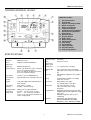
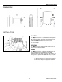
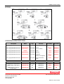
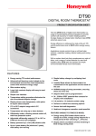
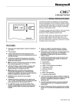
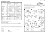
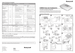
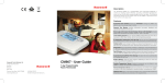
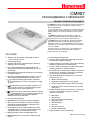
CM907
PROGRAMMABLE THERMOSTAT
PRODUCT SPECIFICATION SHEET
The CM907 thermostat is designed to provide automatic time
and temperature control of heating or cooling systems in
villas and apartments.
It can be used as part of a system in conjunction with combiboilers, oil-burners and gas fired boilers, circulation pumps,
thermal actuators, zone valves and electric heat systems
(<8A).
The CM907 is designed with the installer in mind and
includes a moulded back-plate with trunking guides and
wiring breakouts to make installation quick and easy.
The CM907 extra large LCD display, dynamic text display,
button layout based on the same simple programming
philosophy used on our acclaimed CM60 products and the
introduction of an ‘OK’ button, makes it easier to install and
more user friendly.
The unit is ideal for consumers who want reliable precise
temperature control from a modern looking, simple to
program and easy to use product.
FEATURES
•
•
•
•
•
•
•
•
•
•
•
•
•
•
•
Attractive, slim, ultra-modern styling makes it ideal for
location in any type of home.
7-day heating program.
A dynamic text display on the LCD that gives enhanced
feedback to the user / installer.
Up to 6 daily independent time and temperature level
changes let you set 6 time and temperatures pairs to suit
your lifestyle.
LCD Backlighting to illuminate the display for easier viewing
in low light conditions.
Temporary programmed temperature override to override
the programmed temperature till the next switch point.
•
•
•
•
•
•
•
Holiday button that provides energy savings by reducing
to a constant temperature from 1 to 99 days when people are
on holiday, returning to normal operation (AUTO or
MANUAL) on the day of their return.
Room Temperature Enquiry.
EEPROM memory holds the user program indefinitely.
OFF position has an integral frost protection setting at
minimum 5°C (installer adjustable) so that pipes in the
house will never freeze in winter.
24...230V 8A resistive, 3A inductive SPDT relay provides
compatibility with most domestic central heating systems
reducing the need to stock many different models.
Automatic Summer / Winter time change adjusts the time
automatically to daylight saving time.
Telephone interface can be fitted to allow remote switching
between program modes and a fixed set-point.
Surface or wall-box mounting options with trunking guides
and wiring breakouts to simplify installation.
No installer links or special installer switches on the back of
the unit mean no adjustment is required for combi-boilers
and most domestic central heating systems.
User Set-Up Mode allows extra functions to be set at the
discretion of the user:
•
•
•
•
Party feature that temporarily maintains a selectable
constant temperature for 1-23 hours, then returns to normal
operation.
Day Off feature that follows Sunday’s program for 1 to
99 days, allowing selection of a different heating program
without having to re-program the thermostat.
Built-in default heating program.
•
AM-PM or 24hr time display.
Resetting the heating profile to factory default.
Enable / disable of Auto Summer / Winter time change.
Languages selection of the user interface (on selected
models only).
Installer Set-Up Mode allows extra functions to be set at the
discretion of the installer to match the consumers
applications and needs:
•
•
•
•
•
•
•
•
Optimisation.
Pump Exercise.
Upper / Lower Set point Limit Adjust.
Temperature offset.
Minimum ON time.
Cycle rate.
Heat / Cool operation.
Proportional Band Width.
Diagnostic Mode to assist in faultfinding.
Battery powered by 2 x AA size (LR6) alkaline cells.
Minimum battery life of 2 years with low battery warning
indicator.
EN0H 8547 UK07 R3 09/06
CM907 CHRONOTHERM
CONTROLS/DISPLAY LAYOUT
PRODUCT LAYOUT:
1.
2.
3.
4.
5.
6.
7.
8.
9.
10.
11.
12.
13.
14.
15.
16.
17.
18.
19.
Day & Date Display
Time Display
Dynamic Text Display (DTD)
Burner On Indicator
Battery Low Indicator
Temperature Display
Temperature Change Buttons
Information Enquiry Button
Slider Switch
Green OK Button
Program Buttons
Battery Cover
Battery Compartment
Holiday Button
Party Button
Day Off Button
Copy Day Button
Day Select Button
Time Change Buttons
SPECIFICATIONS
Batteries
: 2 x 1.5 V IEC LR6 (AA) Alkaline cells
Battery life
: Minimum 2 years
Battery
replacement
: Program retained in EEPROM
Switch type
: SPDT (potential free)
Electrical rating
: 230 V~, 50...60 Hz, 0.5 A to 8 A resistive
0.5 A to 3 A inductive (0.6 pf)
24 V~, 50...60 Hz, 0.5 A to 8 A resistive
0.5 A to 3 A inductive (0.6 pf)
Time display
: 24 hour or 12 hour AM/PM format
Time keeping
accuracy
Temperature
: ±0.5 K (nominal) @ 20 C, 50% load
control accuracy
3 K Δ/hour
o
Room
Temperature
display range
: From 0 C to 50 C
Control form
: P + I (Proportional + Integral)
Minimum ON
time
: 10% of cycle time (min one minute),
adjustable to 2 to 5 min (see installer set
up)
Cycle rate
: Selectable by application (see installer
set up)
: Typically better than 10 minutes per year
Wiring
: Terminal block capable of accepting
2
wires up to 2.5 mm
Program
: 7-day with 6 daily time and temperature
level changes
Wire access
: Mains wiring – rear right.
Low voltage wiring – rear right.
Time setting
resolution
: Time of day - 1 minute
Program - 10 minute steps
Dimensions
: 133 x 89 x 26 mm (w x h x d)
133 x 175 x 26 mm (w x h x d)
(flap open)
Environmental
: Operating temperature range 0 to 40 C
Shipping and storage temperature range
o
-20 to 55 C
Humidity range 10 to 90% rh, noncondensing
Approvals
: Designed to meet European EN
approvals EN60730-1(Nov 2000),
EN55014-1 (1997), EN55014-2 (2000)
Sensing element : 100K (@ 25 C ) NTC thermistor
o
Temperature
setting range
: Program : 5 to 35 C in 0.5 C steps
o
Frost
: 5 C or equal to lower limit
o
o
(5 C to 21 C). Frost protection does not
work in cooling mode.
o
o
2
o
o
o
EN0H 8547 UK07 R3 09/06
CM907 CHRONOTHERM
INSTALLER SET-UP
To enter the installer set-up mode:
a) Move the slider switch to the OFF position.
b) Press and hold the INFO i button and the two program
buttons ‘< >’ together.
c) The unit will display the first parameter of installer
parameter group category 1 (from n.1 to n.19).
or
buttons to change the factory
d) Press the TEMP
setting. The display will flash indicating that a change has
been made.
e) Press the green OK button to confirm this change and the
display will stop flashing.
f) Press the
+ button to go to the next parameter.
Factory Setting or New Choice
g) Press the program button > to go to category 2 in the
Installer mode (from n.1 to n.5).
Press TEMP
Abbreviated Set-Up Description
e.g. Cl = Clock Format
or
to change
e.g. 12 = AM/PM Format
24 = 24hr Format
h) To exit the installer mode, move the slider switch to the
AUTO or MAN positions.
Installer Set-up Number
(Press
+ or - to change)
e.g. 1 = Clock Format
In Installer set-up we can:
Brief Description of the
Parameter Function.
❑ Set-up specific applications
❑ Enable special features
❑ Establish support for optional accessories
Specific Applications
Setting
Cycle/
Hour
Minimum
ON time
(in minutes)
Heating
What do you need to change?
Note :
a. To change Cycle/Hour, please go to parameter n. 2, category 2
in the installer set-up mode.
b. To change Minimum ON Time, please go to parameter n. 1,
category 2 in the installer set-up mode.
Gas Boilers
(<30KW)
6
1
No action required
Oil Boiler
3
4
1. Set Minimum ON Time to 4 minutes.
2. Set Cycle/Hour to 3.
Thermal Actuator
12
1
Set Cycle/Hour to 12.
Zone valve
6
1
No action required.
Electric heating
(for applications
<8A)
12
1
1. Configure the thermostat for electric heating (set parameter n.3,
category 2 in the installer set up mode to 1).
2. Set Cycle/Hour to 12.
1. Configure the thermostat to allow switching between heating
and cooling modes (set parameter n.4, category 2 in the
installer set-up mode to 1)
2. Set the thermostat accordingly to the required mode of
or
operation (heating or cooling) by pressing the TEMP
buttons together for 5 seconds. Modify the cooling program
as required.
Air
conditioning
Heat Pump/
Air conditioner
3
4
1. Set Minimum ON Time to 4 minutes.
2. Set Cycle/Hour to 3.
Fan coil
6
1
No action required.
3
EN0H 8547 UK07 R3 09/06
CM907 CHRONOTHERM
Special Features
Description
What to do if we wish this
feature
Optimisation (Variable
Start Time)
Adaptive Intelligence
recovery TM
The thermostat will adjust the start time in the
morning/afternoon so the desired temperature is
reached by the start of the program period e.g. Time
o
7:00, Temp 21 C. The thermostat will monitor the
accuracy of the start up and use this information to
modify the calculation for the following day by changing
the ramp rate (initial 3 K/hr) .The system will restrict the
start time to a max of 2 hours.
Note: Optimisation will not work in cooling mode.
Set parameter n.8, category 1 in the
installer set-up mode to 1.
AM-PM/ 24hr Display
Change display format (default 24hr).
Set parameter n.1, category 1 in the
installer set -up mode to 12.
Pump exercise
When enabled the Pump Exercise will switch the relay
on for 1 minute at 12:00 if the relay has not been
switched on since 12:00 the previous day.
While in Holiday mode the Pump Exercise feature, if
enabled, will operate.
Set parameter n.5, category 2 in the
installer set -up mode to 1.
Upper Temperature Limit
The normal upper temperature limit of 35 C can be
o
reduced down to 21 C to save the homeowner energy.
Useful if the homeowner rents to tenants.
Lower Temperature Limit
The normal lower temperature limit of 5 C can be
o
increased up to 21 C to protect the inhabitants from
cold. Useful if the inhabitants include the elderly,
children or disabled.
Set parameter n.7, category 1 in the
installer set -up mode to the desired
limit.
Temperature Offset
If the thermostat is located in a hot/cold location and
cannot be moved because of wiring then the measured/
o
displayed temperature can be adjusted by +/- 3 C.
Useful if the homeowner wants the reading to match
another appliance temperature display.
Set parameter n.12, category 1 in the
installer set -up mode to the desired
offset value.
Proportional Band Width
Can be adjusted up to 3 C (default is 1.5 C) to provide
better temperature control (less overshoot).
Useful for:
a. Well insulated homes with over-sized heating
systems.
b. Air systems with fast response.
Set parameter n.13, category 1 in the
installer set -up mode to the desired
value.
Optional
Accessories
Description
What to do if we wish this
feature
Outside Temperature
Sensor (F42010971 001)
An Outside Temperature Sensor can be fitted, allowing
the homeowner to display the outside temperate on the
thermostat display by pressing the INFO i button. The
thermostat will read the outside temperature every 10
minutes. Outside temperature display range is from -30
o
o
C to +45 C. The sensor can be connected up to 50
meters from the unit.
1. Fit the sensor (instructions
included in the sensor package).
2. Set parameter n. 10, category 1 in
the installer set-up mode to 1.
Remote Temperature
Sensor (F42010972 001)
A Remote Temperature Sensor can be fitted, allowing
the thermostat to control the temperature from another
room or space, where it is inconvenient to locate the
thermostat. It will read the remote sensor every 1
minute. The sensor can be connected up to 50 meters
from the unit. Useful for commercial premises where the
public may tamper with the product.
1. Fit the sensor (instructions
included in the sensor package).
2. Set parameter n. 10, category 1 in
the installer set-up mode to 2.
o
o
o
o
4
Set parameter n.6, category 1 in the
installer set -up mode to the desired
limit.
EN0H 8547 UK07 R3 09/06
CM907 CHRONOTHERM
Parameter
Installer SetUp Number /
Abbreviation
(Press + or keys to select)
Factory Setting
Optional Setting
Installer SetUp Category
(Press
PROG keys
‘< or >’ to
select)
Display
Description
Display/Setting
Description
Category 1: Thermostat Parameters
AM-PM / 24hr
Display
1:Cl
24
24 hr clock display
12
12 hr AM / PM clock display
1
RESET Time /
Temperature
Program
2:rP
1
Time / Temperature
profile set to factory
default
Changes to 0 when
one of the time/temp
profiles are changed
0
Time / Temperature are
as programmed
To restore the factory
profile set to 1
1
Automatic
Summer/Winter
Time Chqnge
3:tC
1
Automatic
Summer/Winter Time
Change Enabled
0
Automatic
Summer/Winter Time
Change Disabled
1
Backlight Display
5:bL
1
Backlight Display
Enabled
0
Backlight Display
Disabled
1
Upper
Temperature Limit
6:uL
35
35°C Upper Temp.
Limit
21 to 34
21°C to 34°C
adjustment in 1°C steps
1
Lower
Temperature Limit
7:LL
5
5°C Lower Temp.
Limit
6 to 21
6°C to 21°C adjustment
in 1°C steps
1
Optimisation
8:0P
0
Optimisation disabled
1
Optimisation enabled
1
Remote Control
Setpoint (e.g. via
telephone module)
9:tS
0
Disabled
1
Enabled
1
Second
Temperature
Sensor
10:SS
0
No sensor fitted
1, 2
1 - Outside Temperature
Sensor fitted
2 - Remote Temp.
Sensor fitted
1
Temperature
Offset
12:tO
0
No offset
-3 to +3
-3°C to +3°C adjustment
in 0.1°C steps
1
Proportional Band
Width
13:Pb
1.5
1.6°C to 3.0°C
adjustment in 0.1°C
steps
1
Reset Parameters
to Factory
Defaults
19:FS
1
Settings are as modified
above
To restore the factory
profile set to 1
1
1.5°C Proportional
Band
All settings held are
the factory defaults.
Changes to 0 when
one of the parameter
values are changed
1
1.6 to 3.0
0
1
‘Category 2: System Parameters (You must press the ‘>’ program key to enter this section)
Minimum boiler
ON Time
1:Ot
1
1 minute minimum ON
time
Cycle Rate
2:Cr
6
6 cycles per hour
(cph) for gas boilers,
zone valves and fancoil
Electric Heat
3:Eh
0
Applications < 3A
Heat / Cool
Change
4:HC
0
Disabled
5
2 - 2 minutes
3 - 3 minutes
4 - 4 minutes
5 - 5 minutes
2
3 - 3 cph
9 - 9cph
12 - 12 cph
2
1
Applications 3 - 5A
2
1
Enabled
2
2 to 5
3, 9, 12
EN0H 8547 UK07 R3 09/06
CM907 CHRONOTHERM
DIMENSIONS
INSTALLATION
LOCATION
The CM907 thermostat is the control element of the heating /
cooling system and, therefore, MUST be located in a position
with good air circulation, at average room temperature and
on an inside wall 1.5 metres, above the floor level. Do not
position the CM907 thermostat near sources of heat
(radiators, hot air vents, TV or lights), near doors or windows,
or in direct sunlight.
MOUNTING
The CM907 thermostat can be mounted directly on the wall
surface or on an electrical wallbox.
WIRING
The CM907 thermostat is designed for fixed wiring only and
must be installed in accordance with the latest l.E.E.
regulations. Ensure the wiring connection to the supply is via
a fuse rated at no more than 8 amps and a Class "A" switch
(having contact separation of at least 3 mm in all poles).
IMPORTANT
1. The installer must be a trained service engineer
2. Disconnect the power supply before beginning
installation
6
EN0H 8547 UK07 R3 09/06
CM907 CHRONOTHERM
WIRING
ORDERING SPECIFICATION
Description
Model
Logo
7-day programmable thermostat
CMT907A1041
Honeywell
7-day programmable thermostat
CMT907A1025
7-day programmable thermostat
Availability
Spec Sheet
English (UK).
Dec 05
ENOH8547
Honeywell
French.
Dec 05
ENOH8547
CMT907A1017
Honeywell
French & Dutch.
Jan 06
ENOH8547
7-day programmable thermostat
CM907i
Honeywell
Italian.
Jan 06
ENOH8547
7-day programmable thermostat
CMT907A1033
Honeywell
Spanish.
Jan 06
ENOH8547
7-day programmable thermostat
CMT907A1066
Honeywell
Hungarian
Mar 06
ENOH8547
German / Portuguese
Oct 06
Czech / Slovakian /
Polish
Oct 06
ENOH8547
7-day programmable thermostat
Literature
CMT907A1074
Honeywell
Model
Logo
Literature
Availability
Spec Sheet
CM900 Remote Temp Sensor
F42010972 001
Honeywell
Multi-lingual
Sep 06
ENOH8554
CM900 Outdoor Temp Sensor
F42010971 001
N/A
Multi-lingual
Sep 06
ENOH8553
CM900 Telephone Interface
Terminal Block
F42010977 001
N/A
Multi-lingual
Sep 06
N/A
Description
Honeywell Control Systems Limited
Newhouse Industrial Estate
Motherwell ML1 5SB
United Kingdom
http://europe.hbc.honeywell.com
EN0H 8547 UK07 R3 09/06