1
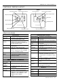
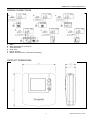
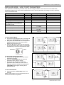
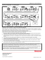
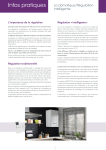
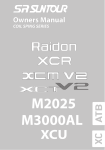
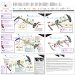
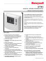
DT90 DIGITAL ROOM THERMOSTAT PRODUCT SPECIFICATION SHEET The new DT90 family of digital room thermostats is a range of market leading products designed to provide comfort with economy in modern heating systems. Its large display and simple button interface make DT90 extremely easy to use. Energy efficiency is addressed by state-of-the-art TPI control performance and an ECO button energy saving feature. Applications include control of gas or oil-fired boiler systems, underfloor heating, electric heating and zoning systems. With a modern fresh look that complements any style of décor, and a range of valued features for users and installers alike, DT90 sets the standard for simple environmentally-friendly room thermostats. FEATURES Energy saving TPI control performance Advanced self-learning control adapts to the environment and ensures close temperature control with minimum energy usage Slim modern styling Large high contrast display with easy-to-read characters Simple user interface Temperature setting procedure eliminates the risk of accidental setpoint change Display shows room temperature, with option to inquire about setpoint 5°C to 35°C setpoint range with 0.5°C increments Simple battery change by unclipping front cover Installer Mode allows the thermostat to be customised for the application and the needs of the user NVRAM storage of setup parameters, ensuring these are never lost Setpoint limits can be programmed in 24…230Vac SPDT potential-free contacts for simple 2-wire installation 8 A resistive, 3 A inductive switch rating Surface or switch-box mounting options Sensor fault self-diagnostics Heat/cool changeover operation mode possible Temperature set using up or down buttons Off/standby button, allowing manual switch off, with frost protection active Adjustable off/standby setpoint 5°C to 16°C or DT90 can be set to off completely Battery powered by 2 x AA (LR6) alkaline cells FEATURES UNIQUE TO DT90E ECO MODEL Energy saving ECO button allows user to change to a lower, energy saving setpoint for a timed period of their choosing (1…24 hours) Display shows countdown of time remaining in ECO energy saving mode Up to 4 years battery life (minimum 2 years), with battery low warning EN0H 8578 UK07 R1 12/08 DT90 DIGITAL ROOM THERMOSTAT CONTROLS / DISPLAY LAYOUT DT90E DT90A frost protect indicator heating demand indicator ECO mode active ECO countdown indicator setpoint change buttons temperature display ECO button setpoint indicator off/standby button fault indicator battery low warning off/standby indicator ECO mode countdown timer SPECIFICATIONS ELECTRICAL TEMPERATURE CONTROL Power supply 2 x 1.5V IEC LR6 (AA) Alkaline cells Sensing element 10K (@25°C ) NTC thermistor Battery life Typically 4 years, minimum 2 years (with correctly specified alkaline cells) Temperature setting range 5°C to 35°C setpoint range in 0.5°C increments Battery low warning Display will indicate when battery power reserve is low. Unit will continue to function for a minimum of 4 weeks after the first indication is given Control form Self-learning TPI Fuzzy Logic algorithm Proportional band 1.5°C adjustable up to 3°C in 0.1°C increments Switch type SPDT (single pole double throw ) potential free Minimum on/off time 1 minute, adjustable up to 5 min in 1 min increments Electrical rating 230 V, 50…60 Hz, 0.01 A to 8 A resistive, 0.1 A to 3 A inductive (0.6pf) Cycle rate Adjustable to suit the application 3, 6, 9, 12 cycles per hour 24 V, 0…60 Hz, 0.01 A to 8 A resistive, 0.1 A to 3 A inductive (0.6pf) Temperature ± 0.5°C (or better) at 20°C, 50% load and control accuracy 3°C /hour temperature ramp Relay life 100,000 operations minimum Frost protection Wiring Terminal block capable of accepting wires up to 2.5mm² Wiring access Rear, top and left side Frost protection not available in cooling mode Positive off Positive off possible (no frost protection) by setting in Installer Mode 0°C to 40°C ECO energy saving Setpoint default 18°C, adjustable 5°C to 35°C -20°C to 55°C Fail-safe operation If temperature measurement system fails, unit will continue to operate on the assumption of a 10% load ENVIRONMENTAL & STANDARDS Operating temperature Shipping & storage temperature Humidity 5°C when thermostat switched to off/standby, adjustable 5°C to 16°C Humidity range 10% to 90% rh, noncondensing IP class IP30 Approvals CE mark, complying with standards METRICS EN60730-1: 2001, EN60730-2-9: 2002 EN55014-1: 2001, EN55014-2: 1997 WEEE & RoSH compliant C-tick 2 Dimensions (unit) Dimensions (pack) Weight (unit) 90 x 92 x 27mm Weight (pack) 192g 93 x 94 x 46mm 165g EN0H 8578 UK07 R1 12/08 DT90 DIGITAL ROOM THERMOSTAT ORDERING SPECIFICATION Model DT90A1008 Description Digital room thermostat Literature Multi-lingual DT90E1012 Digital room thermostat with ECO energy saving feature Multi-lingual MAIN FEATURES Extra-Large Display The DT90 display is more than double the size of its predecessor, ensuring it is even easier to read and allowing more information to be displayed, when required. The large characters and high contrast screen are especially important for those with impaired vision. NVRAM Storage of Settings All parameter settings are stored in a special kind of memory called NVRAM so they will be retained indefinitely even if the batteries are removed. Advanced Self-learning TPI Control DT90 uses a self-learning „fuzzy logic‟ time-proportional control algorithm. This form of control is better than conventional PI control as it has a faster response and better performance in steady state conditions. It performs equally well in a wide range of different installations, and ensures energy savings by controlling closer to setpoint and minimising temperature overshoots. Simple Interface The user interface has been made as simple as possible to make DT90 very easy to use. Buttons have been labeled ▲ and ▼ to identify them as the means of increasing and decreasing (respectively) the setpoint temperature. The display normally shows the actual room temperature. When one of the buttons is first pressed, the setpoint temperature is shown flashing, accompanied by the ▲ and ▼ symbols. Further buttons presses will increase or decrease the setpoint in increments of 0.5°C. Additional Energy saving ECO feature In a heating system, one of the best ways to save energy is to reduce the setpoint temperature. The DT90 green ECO button provides a simple and convenient way of doing this for a period of time of the user‟s choice. The ECO energy saving setpoint is pre-defined in the Installer Mode. The factory setting is 18°C, but it can be adjusted (between 5°C and 35°C) to give a timed boost, if required. When the ECO button is pressed, the user is given the chance to set the time required at this new temperature, from 1 hour to 24 hours in 1 hour increments. The display indicates that ECO mode has been set, and will count down the time remaining in energy saving mode. Should they wish to readjust the temperature setting, they can do that too, using the ▲ and ▼ buttons. ECO mode is cancelled simply by pressing the ECO button again. Off/Standby Button, with Frost Protection The off/standby button allows DT90 to switch off the heating (or cooling) system at the touch of a button. To prevent accidental switch-off, the button must be held for 2 seconds to activate the change. When off, DT90 will maintain control at a frost protection setpoint, factory set to 5°C but adjustable between 5 and 16°C. If required, frost protection can be switched off, to provide a positive off function. These adjustments are made by entering the DT90 Installer Mode. Installer Mode The Installer Mode is where DT90 can be configured for different applications, and customized to meet the needs of the user. The operating properties that can be adjusted are called parameters, and these are described in detail on page 6. Parameters are as follows: Minimum on/off time Cycle rate Proportional band width Temperature measurement offset Upper setpoint limit Lower setpoint limit Energy saving ECO temperature (on DT90E only) Selection of heat/cool changeover operation Off/Standby setpoint Electric heat operation Reset all parameters to factory settings Installer Mode is entered via a sequence of button presses. The buttons are also used to scroll between parameters and to make changes to their values. 24 …230V 8(3)A SPDT Potential Free Contact Rating The DT90 switching relay has a high specification and wide switching range, suitable for most domestic applications. As the thermostat is battery powered, only a 2 wire connection is required to operate the load. Electric heating loads up to 8A (1.6kW) can be switched directly, but please note that if more than 3A is being switched, the electric heat parameter EH should be set to value = 1 in the Installer Mode. This ensures the relay is operated with a higher energy, to switch higher currents reliably. 3 EN0H 8578 UK07 R1 12/08 DT90 DIGITAL ROOM THERMOSTAT INSTALLATION Location DT90 is for use in normal domestic environments, and so should be located inside the house or building where the ambient temperature is within the range 0 to 40°C. Avoid locations with high levels of condensing moisture. As the temperature control element in the heating/cooling system, DT90 MUST be located in a position with good air circulation at average room temperature on an inside wall 1.2 to 1.5m from the floor. Do NOT position the thermostat near sources of heat (radiators, hot air vents, TV or lights), near doors or window, or in direct sunlight. Mounting DT90 can be mounted directly on the wall or onto an electrical wall box. The unit is supplied in 2 x halves, to enable quick and easy installation of the wiring backplate. CAUTION – isolate power supply and make safe before wiring the unit to prevent electric shock and equipment damage. Installation should be carried out by a qualified Electrician or competent Heating Engineer. Wiring DT90 is for fixed wiring only and must be installed in accordance with the latest Electrical Regulations. Ensure the wiring connection to the supply is via a fuse rated at no more than 8 amps and a switch having contact separation of at least 3mm in all poles (formerly Class “A”). Completing the Installation After wiring is complete, the front piece is attached to the backplate with a hinging action, until it clips into place. 4 EN0H 8578 UK07 R1 12/08 DT90 DIGITAL ROOM THERMOSTAT WIRING CONNECTIONS a. b. c. d. e. f. Boiler Boiler (potential free connection) Thermal actuator Zone valve Electric actuator Electric heat (maximum 1.6kW direct switching) PRODUCT DIMENSIONS 5 EN0H 8578 UK07 R1 12/08 DT90 DIGITAL ROOM THERMOSTAT INSTALLER MODE – APPLICATIONS SETTINGS The DT90 has a special Installer Mode where some features can be adjusted to suit the application and the needs or lifestyle of the user. Each adjustable feature is called a Parameter. These are described below. Parameter Minimum ON/OFF time Cycle rate Proportional band width Temperature measurement offset Upper / Lower temperature limits Energy saving ECO temperature Heating or Cooling operation Off/standby setpoint Electric heat operation Reset parameters Description and typical use DT90 is able to set a minimum limit for the on and off times of the controlled device or appliance, to prevent damage or excessive wear. This minimum time can be set to 1, 2, 3, 4, or 5 minutes, and is particularly important for heating applications with oil boilers, or air conditioning applications with compressors. Recommended settings are shown in the next table. Within the control proportional band, the output will be cycled several times per hour, to give precise temperature control. This can be set to 3, 6, 9, or 12 cycles, depending on the application. Recommended settings are shown in the next table. The proportional band is the temperature band, adjacent to the set temperature point, within which the thermostat will cycle the controlled output (to control the boiler, for example). Above or below this band the output will either be fully on or fully off. The band can be adjusted up to 3°C (default 1.5°C) to provide improved temperature control. This is useful for (a) well-insulated homes with over-sized heating systems or (b) air systems with a fast response If the thermostat is located in a particularly hot/cold location and cannot be moved because of the wiring, then the measured/displayed temperature can be adjusted by +/- 3°C. This is useful if the homeowner wants the reading to match the temperature display on another appliance. The normal upper temperature limit of 35°C can be reduced as low as 21°C to save energy. The normal lower limit of 5°C can be raised as high as 21°C to protect inhabitants from the cold. On the DT90E ECO model, pressing the ECO button immediately puts the thermostat into energy saving mode, where it will control at this predefined temperature for as long as the user wishes. This temperature can be set from 5°C to 35°C. DT90 can be used for heating or cooling applications. If heating/cooling changeover is selected, the thermostat can be manually switched from heating to cooling (and back again) by pressing and holding the ▲ and ▼ buttons together for 3 seconds. When the off/standby button is activated, the DT90 will control to a special off/standby setpoint. By default this is set to 5°C to provide frost protection, but it can be set up to 16°C if required. It can also be set off, by setting the parameter value to -- to provide a positive off function. In cooling mode the default setting is off. If a direct electric heating application > 3A switching current is required, DT90 will use more energy to operate its relay and so ensure the higher current is switched reliably. This provides a means of resetting all the parameters to the factory supplied values. Some parameters require to be set to match specific applications. Recommended settings are shown in the table below. Specific Applications Heating Gas boilers (<30kW) Oil boiler Setting Cycles Minimum / hour on/off time 6 1 3 4 Thermal actuator Zone valve 12 6 1 1 Heatpump / Air conditioner Fan-coil unit 3 4 6 1 Air conditioning What requires to be changed? No changes required 1. Set minimum ON/OFF time to 4 minutes 2. Set cycle rate to 3 cycles/hour Set cycle rate to 12 cycles/hour No changes required 1. Configure the thermostat to allow switching between heating and cooling modes (set parameter HC = 1) 2. Set the thermostat to the required mode of operation (heating or cooling) by pressing the ▲ and ▼ buttons together for 3 seconds when in normal run mode (does not work in off/standby mode). 1. Set minimum ON/OFF time to 4 minutes 2. Set cycle rate to 3 cycles/hour No changes required 6 EN0H 8578 UK07 R1 12/08 DT90 DIGITAL ROOM THERMOSTAT INSTALLER MODE – HOW TO SET PARAMETERS Each parameter is identified by a 2-letter code, and has a range of values. These are shown in the table below, followed by instructions on how to enter Installer Mode, how to select a parameter and change its value, and finally how to exit Installer Mode. Description Minimum ON/OFF time Cycle rate Proportional band width Temperature measurement offset Upper setpoint limit Lower setpoint limit Energy saving ECO temperature (this parameter is only available on the DT90E model) Selection of heat/cool changeover Parameter Ot Cr Pb tO uL LL ES Range of values 1, 2, 3, 4, 5 minutes 3, 6, 9, 12 cycles/hour 1.5 to 3.0°C -3 to 3°C 21 to 35°C 5 to 21°C 5 to 35°C Factory (default) value 1 minute 6 1.5°C 0 35°C 5°C 18°C HC 0 = disable 1 = enable -- = off, 5 to 16°C 0 if < 3A 1 if > 3A 0, 1 0 Off/standby setpoint * OS Electric heat operation EH Reset parameters FS * In cooling mode the off/standby setpoint defaults to OFF 5°C 0 1 (factory settings) To enter Installer Mode: a. Put DT90 into off/standby mode by pressing and holding the off/standby button for 2 seconds. b. Now press and hold both ▲ and ▼ temperature adjustment buttons for 3 seconds, until the display shows the word “Inst”. c. Press the ▲ button to get to the first parameter Ot. The parameter code is shown on the display separated by a colon from the parameter value. Parameter Value To select and change a parameter: d. Use the ▲ and ▼ buttons to move from one parameter to another. e. Press the off/standby button to select the parameter value, ready to change f. Use the ▲ and ▼ buttons to adjust the parameter value. When the correct value is flashing, confirm the selection by pressing the off/standby button again, returning to the parameter menu. To exit Installer Mode: g. Press and hold the off/standby button for 3 seconds Note: Installer Mode will exit automatically after 10 minutes if no buttons are pressed. 7 EN0H 8578 UK07 R1 12/08 DT90 DIGITAL ROOM THERMOSTAT INSTALLER MODE - FLOWCHART ES parameter Only available on DT90E models ENERGY EFFICIENCY AND THE ENVIRONMENT Home energy use is currently responsible for more than ¼ of the total carbon emissions which contribute to climate change. Heating and hot water systems based on boilers account for 2/3 of this figure, so it is important to understand how controls can help to maximize energy efficiency while maintaining comfort. DT90 temperature controls should be used in conjunction with appropriate time controls. In order to save energy the following general points should be observed: 1. Ensure the system contains a room temperature thermostat and a hot water temperature thermostat (except for Combi boiler systems), and that both are set to appropriate temperature levels. 2. Programme the heating and hot water to be off when the house is not occupied. If possible frost damage to any exposed pipework is a concern, it is advisable to fit a frost protection thermostat or system. Honeywell can advise on this. 3. It is normal to have the heating system switched off, or set-back at night when heating is not required. 4. Think about how domestic hot water is used. In a storage system, it is not necessary to have this switched on all the time, even when the house is occupied. 5. Do not programme excessive heatup times for the central heating. If the occupier is out of the house, or still in bed, much of this heating would be unnecessary. 6. In the evening, when the house is up to temperature, it is often possible to switch the heating off up to an hour before going to bed, without any noticeable reduction in comfort. The DT90 product family and its associated documentation and packaging are protected by various intellectual property rights belonging to Honeywell Inc and its subsidiaries and existing under the laws of the UK and other countries. These intellectual and property rights may include patent applications, registered designs, unregistered designs, registered trade marks, unregistered trade marks and copyrights. Honeywell reserves the right to modify this document, product and functionality without notice. This document replaces any previously issued instructions and is only applicable to the product(s) described. This product has been designed for applications as described within this document. For use outside of the scope as described herein, refer to Honeywell for guidance. Honeywell cannot be held responsible for misapplication of the product(s) described within this document. Manufactured in the UK, for, and on behalf of the Environmental and Combustion Controls Division of Honeywell Technologies Sàrl, ACS-ECC EMEA, Z.A. La Pièce 16, 1180 Rolle, Switzerland by its Authorised Representative Honeywell Inc. Honeywell Control Systems Ltd. Newhouse Industrial Estate, Motherwell ML1 5SB, United Kingdom http://europe.hbc.honeywell.com EN0H 8578 UK07 R1 12/08