1
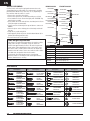
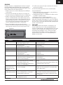
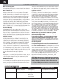
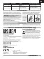
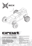
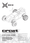
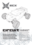
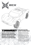
®
TORMENT
™
ECX03006 | ECX03006AU | ECX03006I
ECX03007 | ECX03007AU | ECX03007I
INSTRUCTION MANUAL
BEDIENUNGSANLEITUNG
MANUEL D’UTILISATION
MANUALE DI ISTRUZIONI
1/10 ELECTRIC
SHORT COURSE TRUCK
Congratulations on your purchase of the ECX®
Torment™ Short Course Truck. This 1/10-scale
model introduces you to the sport of RC driving.
Herzlichen Glückwunsch zum Kauf des ECX
Torment Short Course Truck. Dieses 1/10 Scale
Model öffnet Ihnen die Welt des RC Car Sports.
Nous vous félicitons pour l’achat du ECX
Torment Short Course Truck. Ce modèle 1/10
vous initie à la conduite RC.
Congratulazioni per l’acquisto di questo Torment
Short Course Truck ECX. Questa vettura in scala
1/10 vi introdurrà nel mondo dei modelli RC.
EN
NOTICE
All instructions, warranties and other collateral documents are subject to change at the sole discretion of Horizon Hobby, Inc. For
up-to-date product literature, visit http://www.horizonhobby.com and click on the support tab for this product.
Meaning of Special Language:
The following terms are used throughout the product literature to indicate various levels of potential harm when operating this product:
NOTICE: Procedures, which if not properly followed, create a possibility of physical property damage AND little or no possibility of injury.
CAUTION: Procedures, which if not properly followed, create the probability of physical property damage AND a possibility
of serious injury.
WARNING: Procedures, which if not properly followed, create the probability of property damage, collateral damage, and serious
injury OR create a high probability of superficial injury.
WARNING: Read the ENTIRE instruction manual to become familiar with the features of the product before operating.
Failure to operate the product correctly can result in damage to the product, personal property and cause serious injury.
This is a sophisticated hobby product and NOT a toy. It must be operated with caution and common sense and requires some basic
mechanical ability. Failure to operate this Product in a safe and responsible manner could result in injury or damage to the product
or other property. This product is not intended for use by children without direct adult supervision. Do not use with incompatible components or alter this product in any way outside of the instructions provided by Horizon Hobby, Inc. This manual contains
instructions for safety, operation and maintenance. It is essential to read and follow all the instructions and warnings in the manual,
prior to assembly, setup or use, in order to operate correctly and avoid damage or serious injury.
Age Recommendation: Not for children under 14 years. This is not a toy.
Safety Precautions and Warnings
As the user of this product, you are solely responsible for operating in a manner that does not endanger yourself and others or
result in damage to the product or property of others.
This model is controlled by a radio signal subject to interference
from many sources outside your control. This interference can
cause momentary loss of control, so it is advisable to always
keep a safe distance in all directions around your model as this
margin will help avoid collisions or injury.
• Never operate your model with low transmitter batteries.
• Always operate your model in open spaces away from
full-size vehicles, traffic and people.
• Never operate the model in the street or in populated areas
for any reason.
• Carefully follow the directions and warnings for this and any
optional support equipment (chargers, rechargeable battery
packs, etc.) you use.
• Keep all chemicals, small parts and anything electrical out of
the reach of children.
• Never lick or place any portion of the model in your mouth as
it could cause serious injury or even death.
• Exercise caution when using tools and sharp instruments.
• Take care during maintenance as some parts may have sharp
edges.
• Immediately after using your model, do NOT touch equipment
such as the motor, electronic speed control and battery,
because they generate high temperatures. You may burn
yourself seriously touching them.
• Do not put fingers or any objects inside rotating and moving
parts, as this may cause damage or serious injury.
• Always turn on your transmitter before you turn on the
receiver in the car. Always turn off the receiver before turning
your transmitter off.
• Keep the wheels of the model off the ground when checking
the operation of the radio equipment.
TABLE OF CONTENTS
Safety Precautions and Warnings ....................................2
Water-Resistant Vehicle
with Waterproof Electronics .......................................3
Specifications ................................................................3
Components ....................................................................4
Vehicle Preparations ....................................................4
Charging the Vehicle Battery ............................................4
Initial Charge .....................................................................4
Charging Warnings ...........................................................4
Installing Transmitter Batteries ........................................5
Transmitter Battery Safety Precautions ............................5
Removing the Vehicle Body ..............................................5
Installing the Battery in the Vehicle .................................5
Transmitter controls ..........................................................6
RF Mode ............................................................................6
Getting Started..................................................................7
Installing the Vehicle Body ...............................................7
Operation.........................................................................8
When you are Finished .................................................8
Motor Care ......................................................................8
Maintenance ..................................................................9
Setting the Gear Mesh......................................................9
Electronic Speed Control (ESC) .........................................9
Electrical Layout ................................................................9
Shock Cleaning..................................................................10
Fasteners ...........................................................................10
Binding ..............................................................................11
Troubleshooting Guide ......................................................11
Limited Warranty ...........................................................12
Contact Information ..........................................................12
FCC Information..............................................................13
IC Information .................................................................13
Compliance Information for the European Union .............. 13
Parts Diagrams......................................................................... 50
Parts Lists ..........................................................................52
2
TORMENT
EN
WATER-RESISTANT VEHICLE WITH WATERPROOF ELECTRONICS
Your new Horizon Hobby vehicle has been designed and built with
a combination of waterproof and water-resistant components to allow you to operate the product in many “wet conditions,” including
puddles, creeks, wet grass, snow and even rain.
While the entire vehicle is highly water-resistant, it is not
completely waterproof and your vehicle should NOT be treated
like a submarine. The various electronic components used in the
vehicle, such as the Electronic Speed Control (ESC) and servo(s)
are waterproof, however, most of the mechanical components are
water-resistant and should not be submerged.
Metal parts, including the bearings, hinge pins, screws and nuts,
as well as the contacts in the electrical cables, will be susceptible
to corrosion if additional maintenance is not performed after running in wet conditions. To maximize the long-term performance
of your vehicle and to keep the warranty intact, the procedures
described in the “Wet Conditions Maintenance” section below
must be performed regularly if you choose to run in wet conditions.
If you are not willing to perform the additional care and maintenance required, then you should not operate the vehicle in those
conditions.
CAUTION: Failure to exercise caution while using this
product and complying with the following precautions
could result in product malfunction and/or void the warranty.
General Precautions
• Read through the wet conditions maintenance procedures and
make sure that you have all the tools you will need to properly
maintain your vehicle.
• Not all batteries can be used in wet conditions. Consult the
battery manufacturer before use. Do not use Li-Po batteries in
wet conditions.
• The included transmitter is not waterproof or water-resistant. If
using a different transmitter than the one included, consult your
transmitter's manual or the manufacturer before operation.
• Never operate your transmitter or vehicle where lightning may
be present.
• Do not operate your vehicle where it could come in contact
with salt water (ocean water or water on salt-covered roads),
contaminated or polluted water. Salt water is very conductive
and highly corrosive, so use caution.
• Even minimal water contact can reduce the life of your motor if
it has not been certified as water-resistant or waterproof. If the
motor becomes excessively wet, apply very light throttle until
the water is mostly removed from the motor. Running a wet
motor at high speeds may rapidly damage the motor.
• Driving in wet conditions can reduce the life of the motor.
The additional resistance of operating in water causes excess
strain. Alter the gear ratio by using a smaller pinion or larger
spur gear. This will increase torque (and motor life) when
running in mud, deeper puddles, or any wet conditions that will
increase the load on the motor for an extended period of time.
Wet Conditions Maintenance
• Remove the battery pack(s) and dry the contacts. If you have an
air compressor or a can of compressed air, blow out any water
that may be inside the recessed connector housing.
• Remove the tires/wheels from the vehicle and gently rinse the
mud and dirt off with a garden hose. Avoid rinsing the bearings
and transmission.
NOTICE: Never use a pressure washer to clean your vehicle.
• Use an air compressor or a can of compressed air to dry the
vehicle and help remove any water that may have gotten into
small crevices or corners.
• Spray the bearings, drive train, fasteners and other metal parts
with WD-40® solvent or any other water-displacing light oil.
Do not spray the motor.
• Let the vehicle air dry before you store it. Water (and oil) may
continue to drip for a few hours.
• Increase the frequency of disassembly, inspection and
lubrication of the following:
• Front and rear axle hub assembly bearings.
• All transmission cases, gears and differentials.
• Motor—clean with an aerosol motor cleaner and re-oil the
bushings with lightweight motor oil.
SPECIFICATIONS
Transmitter
Frequency
Modulation
Battery
2.4GHz
DSM, DSM2, Marine
AA x 4
Servo
Power Supply
Output Torque
Operating Speed
Size
4.8V~6V (shared with receiver)
41.66 oz (3 kg-cm)
0.23sec/60 degrees of travel
55.6 x 18 x 30mm
Electronic Speed Control (ESC)
Input Voltage
Electric Capacity (FET)
Electric Capacity (FET)
PWM Frequency
BEC Voltage
Size
Weight
4.8–8.4V
Forward 30 A/300 A
Reverse 15 A/150 A
1kHz
5.6 V/1 A
46.4 x 36.9 x 28.25mm
76 g
TORMENT
3
EN
COMPONENTS
1.
2.
3.
4.
5.
ECX Torment 1/10-scale Short Course Truck
Spektrum™ DX2E Transmitter
AA (4) Batteries
DYN4113 2A Peak Battery Charger
Dynamite® Speedpack™ 7.2V
Ni-MH battery (DYN1050EC)
®
™
3
ST. TRIM
R
POWE
ST. RATE
4
TH. TRIM
1
2
5
VEHICLE PREPARATIONS
CHARGING THE VEHICLE BATTERY
1. Connect the AC power cord to the power slot on the charger, then
connect the other end of the power cord to an AC power source.
2. The Power LED and Charging LED will turn GREEN when the
charger is connected to the AC power source.
3. Connect the battery pack connector to the charge connector.
4. Press the On/Off button to charge the battery. The Charging LED
turns RED.
5. When the battery pack is fully charged, the Charging LED will turn
GREEN.
6. Press the On/Off button to stop charging. Disconnect the battery
pack connector from the charge connector.
CAUTION: If at any time during the charge process the
battery pack(s) becomes hot to the touch, unplug the
battery immediately and discontinue the charge process.
The vehicle battery charger produces 2000 milliAmps (2 Amps) per
hour. Divide the mAh capacity on the label of a battery by 2000 to
know how long battery charging will require. For example, a fully
discharged 1800mAh battery requires 0.9 hours (54 minutes) to
charge.
INITIAL CHARGE
Your Dynamite peak voltage detection charger includes safety circuitry and programming allowing the charger to stop charging after 15
minutes, if it senses any issues that have come up in charging. The
high electrical resistance commonly found in new, unconditioned,
Ni-MH batteries can cause this safety circuit to activate turning the
charger off before a full charging cycle is complete. This is commonly
known as a “false peak” in your battery charge.
Should this occur during your first charge cycle, it does not necessarily indicate a failure of either your charger or battery. Instead it
shows that the charger is functioning properly and that the battery is
not yet fully conditioned.
To complete your first full charging cycle in the event of a false peak,
restart the charger by pressing the Start button again. Repeat this
process until the charge cycle continues to charge past 15 minutes.
4
TORMENT
It may take as many as 2 to 4 restarts to complete your first one or
two full charge cycles. Once your charger completes a charge cycle
longer than 15 minutes, your battery will be fully charged. A typical
first full-charge cycle should run for 45 to 90 minutes, depending on
the self-discharge condition of the battery since it was shipped from
the factory.
Once your battery is properly conditioned through a few full charge
and discharge cycles, you will see normal operation of the charger
by a single press of the start button, followed by a 60 to 90 minute
charge cycle.
CHARGING WARNINGS
WARNING: Failure to exercise caution while using this
product and comply with the following warnings could result
in product malfunction, electrical issues, excessive heat, FIRE, and
ultimately injury and property damage.
• Read all safety precautions and literature prior to use of this
product.
• Never leave the battery and charger unattended during use.
• Never allow children under 14 years of age to charge battery
packs.
• Never attempt to charge dead or damaged batteries.
• Never charge a battery if the cable has been pinched or shorted.
• Never allow batteries or charger to come into contact with
moisture at any time.
• Never charge batteries in extremely hot or cold places
(recommended between 50–80°F (10–26°C)) or place in direct
sunlight.
• Always use only Ni-MH rechargeable batteries. This charger
cannot charge batteries such as “heavy duty”, “alkaline”,
“mercury” or “lithium” battery.
• Always connect to the charger correctly.
• Always disconnect the battery and charger after charging and let
them cool between charges.
• Always inspect the battery before charging.
• Always terminate all processes and contact Horizon Hobby if the
product malfunctions.
• Always make sure you know the specifications of the battery to
be charged or discharged to ensure it meets the requirements of
this charger.
• Always constantly monitor the temperature of the battery pack
while charging.
• Always end the charging process if the charger or battery
becomes hot to the touch or starts to change form during the
charge process.
• Always charge in a well ventilated area.
EN
INSTALLING TRANSMITTER BATTERIES
We recommend using only alkaline AA batteries in the
transmitter, however, it is possible to use rechargeable NiMH
batteries.
CAUTION: If using rechargeable batteries, charge only
rechargeable batteries. Charging non-rechargeable
batteries may cause the batteries to burst, resulting in injury to
persons and/or damage to property.
1. Slide the panel open on the bottom of the transmitter.
2. Obey the battery plus (+) and minus (-) diagram in the
transmitter to install 4 AA batteries.
3. Slide the panel closed.
• NEVER install damaged batteries, batteries of mixed types
or batteries of different ages in the transmitter. Remove
exhausted batteries.
• NEVER store the transmitter with batteries installed.
TRANSMITTER BATTERY SAFETY PRECAUTIONS
• Never install damaged batteries.
• Never install batteries of mixed types or of different ages in
the transmitter.
• Always remove exhausted batteries.
• Always remove batteries before storing the transmitter.
• Low battery power can result in loss of control of the RC
vehicle.
REMOVING THE VEHICLE BODY
INSTALLING THE BATTERY IN THE VEHICLE
1. Turn the battery clips (A) clockwise to remove the battery strap (B).
2. Install a fully charged battery.
3. Install the battery strap.
4. Turn the battery clips counterclockwise to secure the battery strap.
If desired, you can put foam blocks (ECX2015) in front of the battery
so the weight of the battery increases rear traction or in back of the
battery to increase steering response.
B
A
TORMENT
5
EN
TRANSMITTER CONTROLS
REVERSE SWITCH
BIND
ST
TH
BIND
N
R
N
R
ST
N
TH
R
N
R
Allows you to change the
direction of steering (ST. REV)
and throttle (TH. REV) controls
(default settings are “N” for
steering and “R” for throttle).
STEERING RATE
STEERING TRIM
Adjusts the amount the
front wheels move when the
steering wheel is turned left
or right.
Adjust to make the vehicle
drive straight with no input
at the steering wheel.
STEERING WHEEL
THROTTLE TRIM
ST. TRIM
POWER
Adjusts the neutral point
of the electronic speed
control.
ST. RATE
TH. TRIM
POWER SWITCH
POWER
Power on
or off the
transmitter.
BATTERY LEVEL
INDICATOR
Solid Green: Battery
voltage is good (above
4V).
Flashing Green: Battery
voltage is critically low
(below 4V). Replace
batteries.
Control steering. Right and
Left steering with ST. REV
Switch on N
(see ST. REV switch).
THROTTLE TRIGGER
Forward
Stop
(when TH.
REV switch on R).
Reverse
(when TH.
REV switch
on R).
Controls power to motor for forward
or reverse (see TH. REV switch).
RF MODE
The DX2E has a France RF Mode that complies with French
regulations. The DX2E must be in France mode when used
outdoors in France. At all other times, the transmitter should be
in Standard mode.
FRANCE MODE
Turn the wheel full left, pull the trigger full throttle, and hold
down the bind button while turning on the transmitter. The
Green LED will flash twice.
6
TORMENT
STANDARD MODE (DEFAULT PRESET SET AT FACTORY)
Turn the wheel full right, pull the trigger full throttle, and hold
down the bind button while turning on the transmitter. The
Green LED will flash once.
EN
GETTING STARTED
2. Power on the ESC.
1. Power on the transmitter.
ST. TRIM
POWER
ST.
TH. TRIM
3. Do a test of the transmitter’s control of the vehicle with
the vehicle’s wheels off the ground.
4. Start driving slowly, and, if the vehicle does not go
straight, adjust the steering trim dial on the transmitter.
IMPORTANT: Seat the motor brushes by driving smoothly
on a flat surface during use of the first battery charge.
Properly seating the motor brushes will increase the life and
performance of the motor.
INSTALLING THE VEHICLE BODY
TORMENT
7
EN
OPERATION
• ALWAYS turn on your transmitter before you turn on the
receiver in the vehicle. Always power off the receiver before
turning your transmitter off.
• ALWAYS operate your vehicle in a wide open area. Operating
the vehicle in a small space or indoors can cause overheating
at low speeds. Operating at low speed increases heat in the
electronic speed control (ESC). Overheating can damage the
vehicle and failure may result.
WHEN YOU ARE FINISHED
1. Power off the Electronic
Speed Control (ESC).
2. Disconnect the battery.
3. Power off the transmitter.
ST. TRIM
POWER
TH. TRIM
5. Recharge the battery.
4. Remove the battery from the vehicle.
MOTOR CARE
• Seat the motor brushes by driving smoothly on a flat surface
during use of the first battery charge. Failing to do so can
greatly reduce motor performance and functional life.
• Prolong motor life by preventing overheating conditions.
Undue motor wear results from frequent turns, stops and
8
TORMENT
starts, pushing objects, driving in deep water and tall grass,
and driving continuously up hill.
• Over-temperature protection is installed on the ESC to
prevent circuit damage, but cannot protect the motor from
driving against heavy resistance.
EN
MAINTENANCE
SETTING THE GEAR MESH
The gear mesh has already been set at the factory. Setting the
gear mesh is only necessary when changing motors or gears.
You must remove the vehicle’s gear cover (A) to make this
adjustment.
Proper gear mesh (how the gear teeth meet) is important to the
performance of the vehicle. When the gear mesh is too loose, the
spur gear could be damaged by the pinion gear of the motor. If
the mesh is too tight, speed could be limited and the motor and
ESC will overheat.
Set the gear mesh by following these simple steps:
1. Loosen the 2 motor screws (B).
2. Put a small piece of paper (C) between the pinion and spur
gears.
B
C
A
3. Push the gears together while tightening the motor screws.
4. Rotate the gears to remove the paper. The gearing should
move a small amount.
5. Reinstall the gear cover.
ELECTRONIC SPEED CONTROL (ESC)
NOTICE: The ESC (DYN4925WP) is compatible with NiCd and
NiMH batteries only. Not for use with LiPo or LiFe batteries.
Programming: This is an auotprogramming ESC. The ESC autoprograms each time the vehicle is turned on.
Operation
LED Color
LED Status
Sound
Stop
Forward
Forward (full speed)
Reverse
Reverse (full speed)
Brake
Overheat
Motor Stalled
Battery Over Voltage (over 9V)
Battery Under Voltage (4.5V)
Solid Green
All
Red
All
Green
All Solid
All LEDs
Red LED
All LEDs
All LEDs
ON
OFF
ON
OFF
ON
ON
LEDs alternately flashing
Flashing quickly 3 times, stopping, then repeating
Solid Red LED. Green LED flashing once per second
Solid Green LED. Red LED flashing once per second
1 beep per second
1 beep per second
1 beep per second
1 beep per 5 seconds
ELECTRICAL LAYOUT
Part #
Description
A
DYN1172
Motor B
DYN1050EC
Battery 7.2V
C
ECX13000
Waterproof Steering
Servo
D
SPMSR201
Receiver
E
DYN4925WP
Waterproof Electronic
Speed Control (ESC)
F
Channel 1
G
Channel 2
A
E
B
EC3
EC3
D
C
G
For correct operation, Channels 1 and 2
must be used as shown in the wiring diagram.
The motor can be disconnected from the ESC
at the connectors in the wiring.
F
TORMENT
9
EN
SHOCK CLEANING
REAR SHOCK
Oil-filled shocks will require regular maintenance due to the
oil breaking down or getting dirty. This maintenance should be
performed after about every 3 to 5 hours of use, depending on
the conditions that the vehicle is used in.
• Remove the shock from the vehicle.
• Remove the cap from the shock body and dispose of fluid.
• Disassemble the shock. Clean thoroughly with DYN5505. Dry
parts before assembly.
• Re-assemble the shock and refill the shock body with silicone
fluid (30 weight recommended).
• Slowly move the shaft and piston up and down to remove air
bubbles.
• Move the piston to the midway point of the body and install
the cap.
• Wipe off any overflowing fluid.
• When properly filled, the piston should rebound about 3/8 in
(9.5mm) after being pushed in fully.
• Re-install the shock on the vehicle.
ECX1037
ECX1037
ECX1043
ECX1043
ECX1057
ECX1037
ECX1038
ECX1036
ECX1038
ECX1043
ECX1037
ECX1057
ECX1038
ECX1036
ECX1038
ECX1043
ECX1037
ECX1040
ECX1039
ECX1041
ECX1042
ECX1038
ECX1038
Ride Height Adjustment
Ride height is an adjustment that affects the way the vehicle
jumps, turns and goes over bumps. Drop one end of the
vehicle from approximately 6 inches (152 mm) in height onto
a flat surface. When dropping the front of the vehicle, after
the vehicle settles, make sure the front arms are equal and
parallel to the flat surface. Do the same with the rear to make
sure both arms are parallel with the flat surface.
Lowering the front ride height increases steering, but
decreases traction. Lowering the rear ride height increases
traction, but decreases steering.
FRONT SHOCK
ECX1037
ECX1037
Part #
ECX1036
ECX1037
ECX1038
ECX1039
ECX1040
ECX1041
ECX1042
ECX1043
Description
Shock Body Set Shock Caps, Pistons Shock Parts Set Front Shock Shaft (2) Rear Shock Shaft (2) Front Shock Springs (2) Rear Shock Springs (2) Shock O-Ring Set FASTENERS
No.
Description
No.
TAPPING
BINDER HEAD
M3x10mm
TAPPING
BINDER HEAD
M3x12mm
TAPPING
BINDER HEAD
M3x16mm
TAPPING
BINDER HEAD
M3x18mm
TAPPING
FLAT HEAD
M3x10mm
TAPPING
FLAT HEAD
M3x12mm
TAPPING
FLAT HEAD
M3x15mm
10
TORMENT
Description
No.
Description
No.
Description
TAPPING
FLAT HEAD
M2x16mm
STEP SCREW
M3x0.5x7.4mm
WASHER
5x7x0.5mm
BINDER
HEAD
M3x8mm
STEP SCREW
M3x0.5x13.4mm
WASHER
3x8x0.5mm
BINDER
HEAD
M3x12mm
STEP SCREW
M3x0.5x10.5mm
WASHER
2x7x0.5mm
BINDER
HEAD
M3x20mm
SETSCREW
M3x3mm
FLANGED
LOCK NUT M4
BINDER
HEAD
M3x25mm
SETSCREW
M3x12mm
LOCK NUT M3
BUTTON
HEX
M2.5x4mm
SET SHAFT
SCREW
M3x13mm
E-CLIP E2.5
BUTTON
HEX
M2.5x8mm
LOCK WASHER
EN
BINDING
Binding is the process of programming the receiver to recognize
the GUID (Globally Unique Identifier) code of a single specific
transmitter. The DX2E and SR201 are bound at the factory. If you
need to rebind, follow the instructions below.
1. With the receiver off, insert the bind plug into the BIND port
on the receiver.
2. Power the receiver through any other port. The orange LED
will flash continuously, indicating the receiver is in bind mode.
3. With the steering wheel and throttle trigger in the failsafe
positions, normally full brakes and straight steering (see the
Failsafe section on this page for more information), press and
hold the bind button and turn on the transmitter. The green
LED on the front of the transmitter will flash within three
seconds, indicating the transmitter is in bind mode.
4. Release the bind button when the green LED flashes.
Continue to hold the steering wheel and throttle trigger in the
failsafe positions until the LED on the receiver glows solid.
Bind Button
BIND
ST
N
TH
R
N
5. The LED on the receiver will glow solid when the transmitter
and receiver are bound.
6. Remove the bind plug and store it in a convenient place.
You must rebind when:
• Different failsafe positions are desired e.g., when throttle or
steering reversing has been changed.
• Changing receiver types e.g., changing from a DSM® receiver
to a DSM2® or Marine receiver.
• Binding the receiver to a different transmitter.
Some Spektrum receivers, like the SR3001, use a bind button
rather than a bind plug. The binding process is the same with this
receiver, however, instead of inserting the plug before powering up
the receiver, press and hold the bind button while powering up the
receiver to enter bind mode.
FAILSAFE
In the unlikely event that the radio link is lost during use, the
receiver will drive the servos to their preprogrammed failsafe
positions (normally full brakes and straight steering). If the receiver
is turned on prior to turning on the transmitter, the receiver will
enter failsafe mode, driving the servos to their preset failsafe
positions. When the transmitter is turned on, normal control is
resumed. Failsafe servo positions are set during binding (see
binding a receiver above).
R
TROUBLESHOOTING GUIDE
Problem
Short Run Time
Sluggish Action
Controls Reversed
Motor/ESC overheat
Doesn’t Operate
Poor Range
The system will not
connect
Possible Cause
• Battery damaged/not charged
• Motor dirty or brushes worn
• Motor dirty or brushes worn
• Bind in drivetrain
• Vehicle battery is not charged
• ST. REV or TH. REV
• Over-geared for the driving environment
• Transmitter batteries low
• Transmitter powered off
• ESC powered off
• Vehicle battery is not charged
• Transmitter batteries low
• Transmitter antenna is damaged or loose
• Receiver antenna damaged
• Transmitter and receiver too near each other
• Transmitter and receiver too near large
metal objects (vehicles, etc.)
• Receiver accidentally put in bind mode so
receiver is no longer bound
• Check the receiver antenna to be sure it is
not cut or damaged
The receiver goes into
failsafe mode a short
distance away from the
transmitter
The receiver quits re• Low battery voltage
sponding during operation • Loose or damaged wires or connectors
between battery and receiver
Receiver loses its bind
• Transmitter accidentally put in bind mode,
ending bind to receiver
Solution
• Check/change battery
• Check/clean/replace
• Check/clean/replace
• Clean/adjust
• Replace/recharge
• Change switch position
• Install smaller pinion
• Replace/recharge
• Power On
• Power On
• Replace/recharge
• Replace/recharge
• Check/tighten
• Check/repair/replace
• Move transmitter 8–12 feet (2.4–3.6m) from
receiver
• Move away from large metal objects (vehicles, etc.)
• Rebind transmitter and receiver
• Contact Horizon Product Support
• Make sure receiver antenna is in an antenna tube
and is above vehicle
• Completely recharge battery
• Do a check of the wires and connection between
battery and receiver. Repair or replace wires and/
or connectors
• Bind transmitter to receiver
TORMENT
11
EN
LIMITED WARRANTY
What this Warranty Covers
Horizon Hobby, Inc. (“Horizon”) warrants to the original purchaser
that the product purchased (the "Product") will be free from defects in
materials and workmanship at the date of purchase.
What is Not Covered
This warranty is not transferable and does not cover (i) cosmetic
damage, (ii) damage due to acts of God, accident, misuse, abuse,
negligence, commercial use, or due to improper use, installation,
operation or maintenance, (iii) modification of or to any part of the
Product, (iv) attempted service by anyone other than a Horizon Hobby
authorized service center, (v) Product not purchased from an authorized Horizon dealer, or (vi) Product not compliant with applicable
technical regulations.
OTHER THAN THE EXPRESS WARRANTY ABOVE, HORIZON MAKES
NO OTHER WARRANTY OR REPRESENTATION, AND HEREBY
DISCLAIMS ANY AND ALL IMPLIED WARRANTIES, INCLUDING,
WITHOUT LIMITATION, THE IMPLIED WARRANTIES OF NON-INFRINGEMENT, MERCHANTABILITY AND FITNESS FOR A PARTICULAR
PURPOSE. THE PURCHASER ACKNOWLEDGES THAT THEY ALONE
HAVE DETERMINED THAT THE PRODUCT WILL SUITABLY MEET THE
REQUIREMENTS OF THE PURCHASER’S INTENDED USE.
Purchaser’s Remedy
Horizon’s sole obligation and purchaser’s sole and exclusive remedy
shall be that Horizon will, at its option, either (i) service, or (ii)
replace, any Product determined by Horizon to be defective. Horizon
reserves the right to inspect any and all Product(s) involved in a warranty claim. Service or replacement decisions are at the sole discretion of Horizon. Proof of purchase is required for all warranty claims.
SERVICE OR REPLACEMENT AS PROVIDED UNDER THIS WARRANTY
IS THE PURCHASER’S SOLE AND EXCLUSIVE REMEDY.
Limitation of Liability
HORIZON SHALL NOT BE LIABLE FOR SPECIAL, INDIRECT, INCIDENTAL OR CONSEQUENTIAL DAMAGES, LOSS OF PROFITS OR
PRODUCTION OR COMMERCIAL LOSS IN ANY WAY, REGARDLESS
OF WHETHER SUCH CLAIM IS BASED IN CONTRACT, WARRANTY,
TORT, NEGLIGENCE, STRICT LIABILITY OR ANY OTHER THEORY OF
LIABILITY, EVEN IF HORIZON HAS BEEN ADVISED OF THE POSSIBILITY OF SUCH DAMAGES. Further, in no event shall the liability of
Horizon exceed the individual price of the Product on which liability is
asserted. As Horizon has no control over use, setup, final assembly,
modification or misuse, no liability shall be assumed nor accepted for
any resulting damage or injury. By the act of use, setup or assembly,
the user accepts all resulting liability. If you as the purchaser or user
are not prepared to accept the liability associated with the use of the
Product, purchaser is advised to return the Product immediately in
new and unused condition to the place of purchase.
Law
These terms are governed by Illinois law (without regard to conflict of
law principals). This warranty gives you specific legal rights, and you
may also have other rights which vary from state to state. Horizon
reserves the right to change or modify this warranty at any time
without notice.
WARRANTY SERVICES
Questions, Assistance, and Services
Your local hobby store and/or place of purchase cannot provide warranty support or service. Once assembly, setup or use of the Product
has been started, you must contact your local distributor or Horizon
directly. This will enable Horizon to better answer your questions and
service you in the event that you may need any assistance. For questions or assistance, please visit our website at www.horizonhobby.
com, submit a Product Support Inquiry, or call 877.504.0233 toll free
to speak to a Product Support representative.
Inspection or Services
If this Product needs to be inspected or serviced and is compliant in
the country you live and use the Product in, please use the Horizon
Online Service Request submission process found on our website
or call Horizon to obtain a Return Merchandise Authorization (RMA)
number. Pack the Product securely using a shipping carton. Please
note that original boxes may be included, but are not designed to
withstand the rigors of shipping without additional protection. Ship
via a carrier that provides tracking and insurance for lost or damaged
parcels, as Horizon is not responsible for merchandise until it arrives
and is accepted at our facility. An Online Service Request is available
at http://www.horizonhobby.com/content/_service-center_renderservice-center. If you do not have internet access, please contact
Horizon Product Support to obtain a RMA number along with instructions for submitting your product for service. When calling Horizon,
you will be asked to provide your complete name, street address,
email address and phone number where you can be reached during
business hours. When sending product into Horizon, please include
your RMA number, a list of the included items, and a brief summary
of the problem. A copy of your original sales receipt must be included
for warranty consideration. Be sure your name, address, and RMA
number are clearly written on the outside of the shipping carton.
NOTICE: Do not ship LiPo batteries to Horizon. If you have
any issue with a LiPo battery, please contact the appropriate
Horizon Product Support office.
Warranty Requirements
For Warranty consideration, you must include your original
sales receipt verifying the proof-of-purchase date. Provided
warranty conditions have been met, your Product will be serviced or
replaced free of charge. Service or replacement decisions are at the
sole discretion of Horizon.
Non-Warranty Service
Should your service not be covered by warranty, service will
be completed and payment will be required without notification or estimate of the expense unless the expense exceeds
50% of the retail purchase cost. By submitting the item for service
you are agreeing to payment of the service without notification.
Service estimates are available upon request. You must include this
request with your item submitted for service. Non-warranty service
estimates will be billed a minimum of ½ hour of labor. In addition you
will be billed for return freight. Horizon accepts money orders and
cashier’s checks, as well as Visa, MasterCard, American Express, and
Discover cards. By submitting any item to Horizon for service, you
are agreeing to Horizon’s Terms and Conditions found on our website
http://www.horizonhobby.com/content/_service-center_renderservice-center.
ATTENTION: Horizon service is limited to Product compliant
in the country of use and ownership. If received, a non-compliant Product will not be serviced. Further, the sender will be
responsible for arranging return shipment of the un-serviced
Product, through a carrier of the sender’s choice and at the
sender’s expense. Horizon will hold non-compliant Product
for a period of 60 days from notification, after which it will be
discarded.
CONTACT INFORMATION
Country of Purchase
Horizon Hobby
United States of America Horizon Service Center
(Electronics and engines)
Horizon Product Support
United Kingdom
Horizon Hobby Limited
12
TORMENT
Address
4105 Fieldstone Rd
Champaign, Illinois
61822 USA
Units 1-4 Ployters Rd
Staple Tye
Harlow, Essex
CM18 7NS
United Kingdom
Phone Number/Email Address
877-504-0233
[email protected]
+44 (0) 1279 641 097
[email protected]
EN
Country of Purchase
Germany
France
China
Horizon Hobby
Address
Horizon Technischer Service Christian-Junge-Straße 1
25337 Elmshorn
Germany
Horizon Hobby SAS
11 Rue Georges Charpak
77127 Lieusaint, France
Horizon Hobby - China
Room 506, No. 97 Changshou Rd.
Shanghai, China 200060
Phone Number/Email Address
+49 (0) 4121 2655 100
[email protected]
+33 (0) 1 60 18 34 90
[email protected]
+86 (021) 5180 9868
[email protected]
FCC INFORMATION
This device complies with part 15 of the FCC rules. Operation is subject to the following two conditions: (1) This device may not cause
harmful interference, and (2) this device must accept any interference
received, including interference that may cause undesired operation.
CAUTION: Changes or modifications not expressly
approved by the party responsible for compliance could void
the user’s authority to operate the equipment.
This product contains a radio transmitter with wireless technology
which has been tested and found to be compliant with the applicable regulations governing a radio transmitter in the 2.400GHz to
2.4835GHz frequency range.
Antenna Separation Distance
maintain a separation distance of at least 5 cm between your body
(excluding fingers, hands, wrists, ankles and feet) and the antenna
to meet RF exposure safety requirements as determined by FCC
regulations.
The following
illustrations show
the approximate
5 cm RF exposure
area and typical
hand placement
when operating
your Spektrum
transmitter.
When operating your Spektrum transmitter, please be sure to
IC INFORMATION
This device complies with Industry Canada license-exempt RSS
standard(s). Operation is subject to the following two conditions:
(1) this device may not cause interference, and (2) this device must
accept any interference, including interference that may cause undesired operation of the device.
COMPLIANCE INFORMATION FOR THE EUROPEAN UNION
Instructions for disposal of WEEE
by users in the European Union
Declaration of Conformity
(in accordance with ISO/IEC 17050-1)
No. HH2013020904
Product(s):
ECX 1/10 th Scale Short Course Truck (Torment) V2.1
(Spektrum DX2E Transmitter and SR201 Receiver included)
Item Number(s):
ECX03006I/ECX03007I
Equipment class:
2
The object of declaration described above is in conformity with
the requirements of the specifications listed below, following
the provisions of the European R&TTE directive 1999/5/EC, EMC
Directive 2004/108/EC and LVD Directive 2006/95/EC:
EN 300-328 V1.7.1: 2006
EN 301 489-1 V1.7.1: 2006
EN 301 489-17 V1.3.2: 2008
EN 60950-1:2006+A11:2009+A1:2010+A12: 2011
EN 55022:2010 + AC:2011
EN 55024:2010
EN 61000-3-2:2006+A1:2009+A2:2009
EN 61000-3-3:2008
Signed for and on behalf of:
Horizon Hobby, Inc.
Champaign, IL USA
Feb 09, 2013
This product must not be disposed of with other waste.
Instead, it is the user’s responsibility to dispose of their
waste equipment by handing it over to a designated
collections point for the recycling of waste electrical
and electronic equipment. The separate collection and recycling
of your waste equipment at the time of disposal will help to conserve natural resources and ensure that it is recycled in a manner
that protects human health and the environment. For more
information about where you can drop off your waste equipment
for recycling, please contact your local city office, your household
waste disposal service or where you purchased the product.
Steven A. Hall
Executive Vice President and Chief Operating Officer
International Operations and Risk Management
Horizon Hobby, Inc.
TORMENT
13
PARTS DIAGRAM | EXPLOSIONSZEICHNUNG | VUE ÉCLATÉE DES PIÈCES |
ESPLOSO DEL MODELLO CON REFERENZA PEZZI
RECOMMENDED ITEMS
EMPFOHLENE WERKZEUGE
OUTILS RECOMMANDÉS
ATTREZZI CONSIGLIATI
M3X10
11
10
M3X10
M3X10
12
30
9
M3X12
5
45
M3X18
51 M3X12
1
2 mm
1.5 mm
3
51
M3X12
M3X12
M3X25
12
M3X18
M3X10
M3X12
2
M3X12
4
7
2
44
20
7
2
45
49
M3X10
8
17
2
2
19
2
7
16
M3X12
19
20
M3X15
20
M3X15
M3X10
M3X25
13
46
8
29
23
7
18
23
M3X15
8
31
15
M3X8
14
13
31
M3X10
52
21
15
19
TORMENT
M3X12
M3X12
22
PARTS DIAGRAM | EXPLOSIONSZEICHNUNG | VUE ÉCLATÉE DES PIÈCES |
ESPLOSO DEL MODELLO CON REFERENZA PEZZI
The slipper clutch can be adjusted using
this locknut (ECX1060). Fully tighten the
locknut, then loosen the nut two full
turns.
42
M3X3
M2.5X8 32
32
41
22 34 34
M2.5X4
Die Rutschkupplung kann durch diese
Stopmutter eingestellt werden (ECX1060).
Ziehen Sie die Mutter an und drehen Sie
dann volle zwei Umdrehungen zurück.
34
34
32
15
M2.5X8
33 48
Il est possible d’ajuster le sliper par action sur cet écrou de blocage (ECX1060).
Veillez à serrer l’écrou de blocage à fond.
Ensuite, devissez l’écrou de trois tours
complets.
15
48
35 15 33 15
6
39
25
36
38 35 33
M3X18
36
M2X16
33
35
La frizione può essere regolata con
questo dado autobloccante (ECX1060).
Prima avvitate completamente il dado,
poi svitatelo 2 giri.
40 33
15
36
M3X12
39
33
33
35
33 35 33
M2X16
38
25
M3X12
43
M3X15
44
M3X12
M3X15
52
45
17
M3X10
M3X10
43
50
M3X12
46
25
M3X12
M3X18
M3X12
M3X12
47
M3X12
M3X10
52
25
M3X20
47
11
M3X12
M3X10
32
39
49
26
29
13
24
M3X15
20
3
27
19
29
32
M3X12
26
19
13
26
23
20
28
20
M3X12
M3X12
When installing the wheel, make sure the drive hex is aligned with the drive pin. When
the drive hex is removed, the drive pin can fall out of the axle.
Bitte achten Sie bei der Radmontage darauf, dass die Radachse im Radmitnehmer
sitzt und dass der der Querstift nicht heraus fällt.
Lors de l’installation de la roue, assurez-vous que l'hexagone de roue est aligné avec la goupille
d'entraînement. En cas de démontage de l'hexagone, la goupille peut sortir de l'axe et tomber.
Quando montate le ruote, accertatevi che il trascinatore esagonale sia allineato con la spina
del mozzo ruota. Quando togliete il trascinatore esagonale la spina può sfilarsi dal mozzo.
27
21
13
15
15
14
13
22
TORMENT
53
Replacement Parts / Ersatzteile / Pièces de rechange / Pezzi di ricambio
Part # | Nummer
Description
Numéro | Codice
1
2
ECX2008
ECX1028
3
ECX2011
4
5
ECX1050
ECX2015
6
ECX1098
7
8
ECX1058
ECX1065
9
SPMSR201
10
ECX13000
11
12
ECX231003
ECX4005
13
ECX2006
14
ECX4003
15
ECX1015
16
ECX1018
17
ECX1020
18
19
ECX1035
ECX1044
20
ECX1046
21
22
ECX1049
ECX1060
23
ECX234000
24
ECX1019
25
ECX1021
26
27
28
ECX232001
ECX232005
ECX232002
29
ECX1045
30
DYN4925WP
31
ECX1037
32
ECX1027
33
ECX1022
34
ECX1024
35
ECX1025
36
ECX1026
37
38
39
40
ECX1052
ECX1055
ECX1059
ECX232006
54
Main Chassis Servo Saver Set Cover and Rear Mount
Set
Setscrew M3x12 (4) Foam Block
Motor Screw/Washer
Set
Ball Stud (6)
Shoulder Screw Set (8)
2-Ch DSM Sport
Receiver (Coated)
Waterproof Steering
Servo
Battery Hold Down
Front Bumper Set
Suspension Arm
Mount Set
Mounted Wheel/
Tire (2)
Wheel Bearing Set Front Suspension Arm
Set Beschreibung
Description
Descrizione
Chassis
Servo Saver Set
Abdeckung und hinterer
Halter Set
Schrauben Set M3x12 (4)
Schaum Block
Set Motorschrauben/
Unterlegscheiben
Kugelkopf (6)
Passschrauben Set (8)
2 Kanal DSM Sport
Empfänger (beschichtet)
Châssis principal
Sauve servo
Telaio principale
Set salvaservo
Copertura e set montaggio
posteriore
Grani M3x12 (4)
Spugna distanziale batteria
Viti per il motore/ set di
rondelle
Sfere Uniball (6)
Set viti a doppio stadio (8)
Ricevitore Sport (con rivestimento protettivo)
Servo per lo sterzo, impermeabile
Piastra fermabatteria
Set paraurti ant
Capot et fixations arrières
Jeu de vis M3x12 (4)
Bloc de mousse
Vis Moteur/Set Rondelles
Rondelle (6)
Jeu de vis épaulées (8)
Récepteur DSM 2 voies
étanche
Lenkservo, wasserdicht
Servo de direction étanche
Akkuhalter
Vordere Stossstange
Querlenker Set hinten
Fixation pour batterie
Jeu de pare-chocs avant
Jeu de renfort de
suspension
Rad montiert (2)
Pneu monté /jante (2)
Jeu de roulement de roue
Jeu
de bras de suspension
Querlenker Set vorne
avant
Jeu de support
Shock Tower Set Dämpferbrücke
d’amortisseur
Front Axle (2) Radachse vorne (2)
Axe de roue avant (2)
Hinge Pin Set Querlenkerbolzen Set
Jeu d'axes de suspension
Jeu
de biellettes de
Camber, Toe Link Set Spur- Sturzstangenset
carrossage et de pincement
Wheel Pins (4) Radmitnehmerstifte (4)
Goupilles d'entraînement (4)
M4 Locknut (4)
M4 Stopmutter (4)
Ecrous de roues M4 (4)
Jeu de fusées avant et
Steering Block, Rear
Lenk- und Rädträger
arrière avec étriers portes
Hub Set
hinten
fusées avant.
Rear Suspension Arm
Jeu de bras de suspension
Querlenker
Set
hinten
Set arrière
Ensemble carter de
Transmission Case Set Getriebegehäuse
transmission
Rear Axle (2) Wellenmitnehmer hinten (2) Axe de roue arrière (2)
Driveshaft Pivot Ball (4) Antriebswellengelenk (4) Croisillon de cardan (4)
Driveshafts (2)
Antriebswellen (2)
Cardan (2)
Querlenkerbolzen
Hinge Pin Screws (8) Vis de fixation de renfort (8)
Schrauben (8)
ESC
Regler / ESC
Variateur électronique
Stoßdmämpferkappen
Bouchon, piston et rotules
Shock Caps, Pistons
Kolben
d’amortisseur
Gear Cover
Getriebeabdeckung
Carter de Réducteur
Couronne et pignons
Transmission Gear Set Getriebe
intermédiaires,corps et
pignons de différentiel.
Slipper Clutch Plates,
Garnitures, plateaux et
Rutschkupplung
Teilesatz
Pads, Spring ressort de slipper.
Arbre secondaire de
Transmission Idler
Hauptgetriebewelle Set
transmission avec goupilles
Shaft, Drive Pins d'entraînement.
Transmission Drive
d’arbre de transmission
Getreibeausgangswelle (2) Axe
Shaft (2) (2)
Washer Set
Unterlegscheiben Set
Jeu de rondelles
Bearings 10x15x4 (2)
Lager 10x15x4 (2)
Roulements 10x15x4 (2)
M3 Locknut (4)
M3 Stopmutter (4)
Ecrou auto-freiné M3 (4)
Spur Gear
Hauptzahnrad
Couronne
TORMENT
Radlagersatz Set
Supporti braccetti sosp.
Ruote e gomme montate (2)
Set cuscinetti ruote
Braccetti delle sospensioni
anteriori
Supporto ammortizzatori
posteriori
Mozzi ruota anteriori (2)
Set perni sospensioni
Set tiranteria Camber e
convergenza
Spine trascinatori ruote (4)
Dadi autobloccanti M4 (4)
Set blocco sterzo, mozzo
posteriore
Braccetti delle sospensioni
posteriori
Set scatola trasmissione
Mozzi ruota anteriori (2)
Snodi semiassi (4)
Semiasse (2)
Viti per perni sospensioni (8)
Variatore elettronico (ESC)
Set tappi e pistoni
ammortizzatori
Copertura per ingranaggi
et ingranaggi trasmissione
Piattelli frizione, disco,
molla
Alberino intermedio con
spina
Mozzi Differenziale (2)
Set rondelle
Cuscinetti 10x15x4 (2)
Dadi autobloccanti M3 (4)
Corona
Part # | Nummer
Description
Numéro | Codice
Beschreibung
Description
Descrizione
41
42
43
ECX1073
DYN1172
ECX1048
19-Tooth Pinion Gear
Motor
Body Clip
Ritzel 19 Zähne
Motor
Body Clip
Pignon 19 dents
Moteur
Clips Carrosserie
44
ECX2010
Body Post Set
Karosseriehalterset
Set Plots Carrosserie
45
ECX2009
Body Mount Set
Set Montage Carrosserie
46
47
48
49
50
51
52
ECX2007
ECX2013
ECX1023
ECX1033
ECX4006
ECX4004
ECX4007
SPM2300
Skid Plate Set
Rear Holder Set
Top Shaft/Spacer
Setscrew M3x10
Rear Bumper Set
Nerf Bar Set
Mud Flap Set
Body, Silver/Blue:
Torment
Body, Black/Green:
Torment
Transmitter
Aufnahme
Karosseriehalter
Unterfahrschutz Set
Set Halter hinten
Getriebewelle oben
Sicherungsschrauben (4)
Hinterer Stoßfänger Set
Seitenaufprallschutz
Schmutzfängerset
ECX Torment Karosserie
Silber / Blau
ECX Torment Karosserie
Schwarz/ Grün
Sender
Pignone a 19 denti
Motore
Clippe per carrozzeria
Set di sostegni per la
carrozzeria
Set di montaggio per la
carrozzeria
Set pistre di protezione
Set supporto posteriore
Set di spessori
Viti (4)
Set paraurti posteriore
Set protezione laterale
Set paraspruzzi
DYN4113
2A Peak Charger
2A Peak Ni-MH Ladegerät
DYN1050EC
Ni-MH battery
Ni-MH akku
ECX230006
ECX230007
Set Plaque Chassis
Set de Maintien Arrière
Set de Goupilles
Vis (4)
Set de parechoc arrière
Set de protection latérales
Set de bavettes
Carrosserie argent/bleue Torment
Carrosserie noire/verte Torment
Émetteur
2A Chargeur à détection
de pics
Batterie Ni-MH
Carrozz. Blu/Arg Torment
Carrozz. Nero/Verde Torment
Trasmettitore
2A Caricabatterie a
rilevamento di picchi
Batteria Ni-MH
TORMENT
55
®
ECX03006 | ECX03006AU | ECX03006I
ECX03007 | ECX03007AU | ECX03007I
www.ecxrc.com
37873
Created 1/2013
© 2013 Horizon Hobby, Inc.
ECX, the ECX logo, Torment, Dynamite and Speedpack are trademarks or registered trademarks
of Horizon Hobby, Inc. WD-40 is a registered trademark of WD-40 Manufacturing Company.
The Spektrum trademark is used with permission of Bachmann Industries, Inc.