1
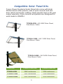
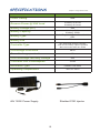
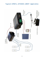
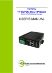
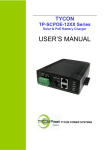
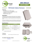
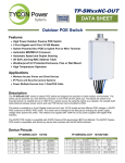
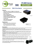
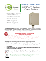
UPS-ST2424-UBNT UPSPro™ Backup Power System ▫ Wireless Base Stations and Client Devices ▫ Surveillance Cameras ▫ Remote Sensors ▫ UBNT Equipment ▫ Microtik Equipment Congratulations! on your purchase of the UPSPro™ outdoor backup power system. Please take a moment to review this Qwik Install Guide before assembly or battery installation. DANGER! Avoid Powerlines! You Can Be Killed! When following the instructions in this guide take extreme care to avoid contact with overhead power lines, lights and power circuits. Contact with power lines, lights or power circuits may be fatal. We recommend to install no closer than 20 feet to any power lines. Safety: For your own protection, follow these safety rules. ▫ ▫ ▫ Perform as many functions as possible on the ground Do not attempt to install on a rainy, windy or snowy day or if there is ice or snow accumulation at the install site or if the site is wet. Make sure there are no people, pets, etc. below when you are working on a roof or ladder. Recommended Tools: Phillips Screwdriver, 13mm and 10mm Open End Wrench, 8mm nut driver, Flat Blade Screwdriv- Please help preserve the environment and return used batteries to an authorized depot Qwik Install STEP 1: Add Grounding Wire Between Door and Enclosure: Remove plastic covers on copper studs on inside of door and inside of enclosure. Add jumper wire between 2 copper studs and use copper washers and nuts to secure. STEP 2: Add wire feedthrus into the bottom connector plate. Attach the connector plate to the bottom of the enclosure using self tapping screws provided. STEP 3: Install hole plug in drain hole in bottom right corner of the enclosure. STEP 4: Mount the DIN rail to the door using screws provided. Mount any extra equipment to the orange backplate and secure the backplate in the enclosure. Note: The DIN rail can also be mounted to the orange backplate or sides of enclosure if desired. STEP 5: mounting sure, If pole the encloassemble 2 the pole mount kit to the back of the enclosure and mount the enclosure to a pole using the 6 hose clamps provided. The enclosure can also be wall mounted using the 4 holes in the back of the enclosure. STEP 6: Insert the battery platform in the bottom of the enclosure. The battery platform has cutouts so wires can be routed under the battery as needed. STEP 7: Attach the green DIN Rail adapters to the charge controller and 5 port POE switch using the screws provided. Clip the controller and POE switch to the DIN rail. STEP 8: Connect a two conductor wire between the back green connector on the con3 troller to the back green connector on the 5 port switch. You can use the included cable with terminal connectors by cutting off terminal connectors and then cutting and stripping cable to proper length. Observe proper polarity for all connections. Note: There are two +V and two V- (GND) connections on the controller and the switch. You can use either connection. The FG connection is for frame ground or earth ground. If your grounding scheme requires it you can connect the FG to the enclosure ground point near the bottom of the door. The FG is common to the RJ45 shield. TP-SCPOE Controller TP POE Switch STEP 9: Install the batteries in the enclosure. Batteries are 12V batteries and need to be connected in series for 24VDC output. 24V two batteries and 24V four batteries configurations are shown here: 4 STEP 10: If batteries are installed on their side make sure to apply an insulator to the top of the battery terminal to prevent the battery terminals from shorting to the metal enclosure in case the battery shifts inside the enclosure during an earthquake. STEP 11: Disconnect the green front connector from the controller. Connect the battery cables to the battery. Be sure to observe polarity. Black wire connects to battery negative terminal and BAT(-) terminal on the controller. After connecting the batteries, plug the green connector into the controller. When a fully charged battery is connected, the Green LOA LED should light on controller and the LED’s on the 5 port switch should power up. Note: green The connector 5 on the controller will become unplugged due to vibration and the weight of the cables. Be sure to add a zip tie or other method to hold the cables and relieve the cable weight from the connector. STEP 12: If you have a solar panel, route the solar panel cable from the solar panel thru one of the feedthrus on the bottom of the enclosure and install to the SOL input of the controller. Be sure to connect in the proper polarity, red wire to + and black wire to –. Make sure any outdoor connections are waterproofed. STEP 13: Tighten all wire feedthrus. If they don’t tighten on a small diameter wire, you can wrap some electrical tape around the wire in the seal area to increase its diameter and make a better seal. The enclosure needs some small amount of venting so be sure NOT to seal all holes and feedthrus with silicon. STEP 14: Make sure lid gasket is clean and free from any particles, then carefully close the cover, making sure that wires are clear of the seam and hinge area. Use the special key to close the two cover locks. TECH CORNER Additional Information you may find useful 1. CONTROLLER: The controller turns off power to the load at 22V and reconnects when the battery reaches 24V. This protects battery from overdischarge and increases battery life and performance. Controller LEDS: POE = ON POE input detects current from POE source. If POE led is flashing it means the power source is too weak for the POE input. Find a power source with more capacity. SOL = ON Solar input detects current from solar panel. CHA = ON Batteries are being charged from solar input. If CHA is flashing it means batteries are fully charged. LOA = ON Battery voltage is sufficient and load outputs (POE OUT and auxiliary wire terminal output) are turned on. REV = ON Battery wires reversed. Fuse: The fuse is in line with battery power. If fuse is blown there was some sort of short in the battery connection and the controller will appear dead. Replace with 10A fuse. 2. CAPACITY: The UPSPro UPS-ST2424-UBNT is rated at up to 60W power output. If you exceed this load the system may not function to expectations. 6 Note: The controller can supply 24V 1A from the POE OUT port and 24V 1.5A from the auxiliary wire terminal port. To utilize the full 60W you can combine the outputs of both ports. Power on the POE port is supplied on Ethernet pins 4,5(+) and 7,8(–). 3. VENTING: The enclosure is vented thru the wire feedthrus and various hole plugs in the bottom of the enclosure. Don’t make these airtight with silicon 4. BATTERY MAINTENANCE: The batteries used in the UPSPro systems don’t require any maintenance. They should last up to 5 years in normal use. Note: Never store batteries for any length of time in a discharged state or it will kill the battery. 5. BATTERY OVERDISCHARGE: We highly recommend hooking all equipment loads to the controller voltage output. This output will disconnect the load if the battery voltage drops below 22V and this will protect the battery from over-discharge. If batteries get completely discharged because the equipment was connected directly to the battery, you will reduce the battery life and you will most likely need to supercharge them with a good quality 10A automotive battery charger. Once they are back to a normal operating range, the integrated charge controller will maintain the charge. 6. WIND TURBINE: A wind turbine can be added to this system at any time. Wind Turbines are good sources of power, often in times when the sun isn’t shining, like on stormy days. We like to think of a wind turbine as uptime insurance. Tycon Power Systems offers small wind turbines perfectly suited to augment the UPSPro systems. The TPW-40024 is a 400W 24V wind turbine. To add a wind turbine, it mounts to the inside diameter of a 41mm ID pole. You will need to mount the controller inside the enclosure and connect the output of the controller to the batteries. The connection will be in parallel with the existing solar controller connection. 7. OTHER ACCESSORIES: Tycon also offers a variety of voltage conversion products to meet almost any need. Just visit tyconpower.com for more info. 7 Compatible Solar Panel Kits Tycon Power Systems Solar Panel kits come with High Performance solar panels, side of pole mounts and outdoor rated connection cabling. Solar panels have a 25 year output warranty. Pole mounts and panels are designed for wind loads to 90MPH. TPSK24-85W—24V 85W Solar Panel, Pole Mount, Cable TPSK24-120W—24V 120W Solar Panel, Pole Mount, Cable TPSK24-240W—24V 240W Solar Panel, Pole Mount, Cable Solar Kits 6 Hours Peak Sun 3 Hours Peak Sun TPSK24-85W 20W continuous 10W continuous TPSK24-120W 30W continuous 15W continuous TPSK24-240W 60W continuous 30W continuous 8 Compatible Wind Turbine TPW-400DT-12/24 400W 12/24V Wind Turbine Includes controller Good low wind performance Self braking in high wind 80MPH survivability Sealed and maintenance free 9 SPECIFICATIONS Subject to change without notice Power Rating 60W 2 battery 20 hours 4 battery 40 hours Reserve Power @ 30W Load Battery Voltage (DC) 24V 2 battery 51Ah 4 battery 102Ah Valve Regulated Sealed Lead Acid / GEL Battery Capacity Battery Type Battery Life 5 Years 24V Solar/POE Charge Controller POE and secondary outputs regulated Max Solar Panel Size 24V 270W Controller Type Overcharge Protection 28.6V Over-discharge protection 20V Over-discharge recovery voltage 22V Controller Self Consumption <0.5W Enclosure Type Powder Coat Steel Operating Temperature -30°C to +60°C 48V 150W Power Supply Shielded POE Injector 10 Typical UPSPro-ST2424-UBNT Application 11 Limited Warranty The UPSPro™ products are supplied with a limited 24 month warranty which covers material and workmanship defects. This warranty does not cover the following: ▫ Parts requiring replacement due to improper installation, misuse, poor site conditions, faulty power, etc. ▫ Lightning or weather damage. ▫ Physical damage to the external & internal parts. ▫ Products that have been opened, altered, or defaced. ▫ Water damage for units that were not mounted according to user manual. ▫ Usage other than in accordance with instructions and the normal intended use. Tycon Power Systems 14641 S 800 W Suite A Bluffdale, UT 84065 [email protected] 8000025 Rev 3 UPS-ST2424-UBNT UPSPro™ Qwik Install Guide 12