1
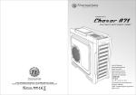
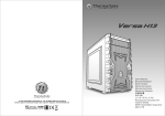
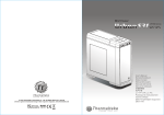
Core V21
Your Build. Our Core
User's Manual
Benutzerhandbuch
Mode d’emploi
Manual del usuario
Manuale dell’utente
Manual do Utilizador
安裝說明書
用戶手冊
ユーザーズマニュアル
Руководство пользователя
kullanıcı elkitabı
(EEE Yönetmeliğine Uygundur)
คู ่ ม ื อ การใช้
© 2014 Thermaltake Technology Co., Ltd. All Rights Reserved. A-2014.10
All other registered trademarks belong to their respective companies. www.thermaltake.com
Tested To Comply
With FCC Standards
FOR HOME OR OFFICE USE
www.thermaltake.com
Contents
Chapter 1. Product Introduction
Micro Case
336 x 320 x 424 mm (13.2 x 12.6 x 16.7 inch)
Side Panel
Transparent Window
1.1
Specification
02
Material
SPCC
1.2
Accessory
02
Cooling System
Front (intake) :
200 x 200 x 30 mm fan (800rpm, 13dBA)
1.3
Warning and Notice
03
Drive Bays
-Hidden
3 x 3.5” , 3 x 2.5”
Expansion Slots
5
Motherboard
6.7" x 6.7" (Mini ITX) , 9.6" x 9.6" (Micro ATX)
I/O Port
USB 3.0 x 2, HD Audio x 1
Chapter 2. Installation Guide
2.1
Side Panel Disassembly
05
2.2
PSU Installation
06
2.3
Motherboard Installation
07
2.4
3.5" & 2.5" HDD Installation
08
2.5
2.5" HDD Installation
09
2.6
PCI Slot Usage
10
2.7
Air Cooling Installation
11
2.8
Liquid Cooling Installation
12
2.9
Bracket Installation
13
2.10
I/O Panel Placement Guide
14
2.11
Stacking Installation
15
Chapter 3. Leads Installation
3.1
Case LED Connection
3.2
USB 3.0 Connection
16
3.3
Audio Connection
16
16
Chapter 4. Other
4.1
Thermaltake Power Supply Series (Optional)
*Picture for reference only
*Information in the user manual is subject to change without notice
1
Case Type
Dimension (H*W*D)
22
Clearance
Figure
CPU cooler height limitation: 185mm
VGA length limitation: 350mm
PSU length limitation: 200mm (Without bottom fan)
Parts Name
Q ' ty
Screw # 6-32 x 6 mm
4
PSU
PSU Rubber
2
PSU (Bottom)
PSU
Used for
PSU Bracket 1
1
PSU Bracket 2
1
PSU
Screw # 6-32 x 6 mm
1
PSU Bracket
Stand-off # 6-32 x 6 mm
2
Motherboard
Screw # 6-32 x 5 mm
9
Motherboard
Screw M3 x 6 mm
18
2.5"HDD
Screw Ø 5 x 10 mm
12
Fan
Cable Tie
7
Cable Management
Screw # 6-32 x 15 mm
2
Stacking
Flange Nut # 6-32
2
Stacking
Stacking Gasket
2
Stacking
2
Warning and Notice
CPU Cooler Height Limitation
VGA ( Add- on card) Length Limitation
Atenção!!
- Limite de altura para o dissipador do CPU:
O limite de altura para o dissipador do CPU é 185 mm (7,3 polegadas).
- Limite de comprimento para VGA (placa gráfica):
O limite de comprimento para VGA (placa gráfica) é 350 mm (13.8 polegadas).
<185 mm
警告!!
- CPU散熱器的高度限制:
CPU散熱器的高度限制為185mm(7.3英吋)。
<350 mm
- VGA(顯示卡)的長度限制:
VGA(顯示卡)的長度限制為350mm(13.8英吋)。
警告!!
Warning!!
- Height limit for the CPU heatsink:
The height limit for the CPU heatsink is 185 mm (7.3 inches).
- Length limit for the VGA (graphics card):
- CPU散热器的高度限制:
CPU散热器的高度限制为185mm(7.3英寸)。
- VGA(显卡)的长度限制:
VGA(显卡)的长度限制为350mm(13.8英寸)。
The length limit for the VGA (graphics card) is 350 mm (13.8 inches).
警告
Warnung!!
- Höhenbeschränkung für CPU-Kühler:
Die Höhenbeschränkung für den CPU-Kühler liegt bei 185 mm (7,3 Zoll).
- Längenbeschränkung für die VGA (Grafikkarte):
- CPUヒートシンクの高さ制限:
CPUヒートシンクの高さ制限は185 mmです。
- VGA(グラフィックスカード)の長さ制限:
VGA(グラフィックスカード)の長さ制限は350 mmです。
Die Längenbeschränkung für die VGA (Grafikkarte) beträgt 350 mm (13.8 Zoll).
Внимание!
Avertissement !
- Hauteur limite du dissipateur thermique du processeur :
La hauteur limite du dissipateur thermique du processeur est de 185 mm (7,3 pouces).
- Longueur limite de la carte VGA (carte graphique) :
- Ограничение по высоте для радиатора ЦП.
Ограничение по высоте для радиатора ЦП составляет 185 мм (7,3 дюйма).
- Ограничение по длине для платы VGA (графическая плата).
Ограничение по длине для платы VGA (графическая плата) составляет 350 мм (13.8 дюйма).
La longueur limite de la carte VGA (carte graphique) est de 350 mm (13.8 pouces).
Uyarı!!
Precaución
- Límite de altura para el disipador de calor de la CPU:
El límite de altura para el disipador de calor de la CPU es de 185 mm (7,3 pulgadas).
- Límite de longitud para la tarjeta gráfica (VGA):
El límite de longitud para la tarjeta gráfica (VGA) en de 350 mm (13.8 pulgadas).
CPU ısı alıcısı için yükseklik sınırı 185 mm’dir (7,3 inç).
- VGA (grafik kartı) için uzunluk sınırı:
VGA (grafik kartı) için uzunluk sınırı 350 mm’dir (13.8 inç).
- Kasaya üst ön fanı takıyorsanız, lütfen ilk 5,25” bölmesine aygıt takmayın.
Attenzione!
คำเตื อ น!!
- Limite di altezza per il dissipatore di calore della CPU:
- ขี ด จำกั ด ความสู ง สำหรั บ ฮี ต ซิ ง ก์ ข อง CPU:
Il limite di altezza per il dissipatore di calore della CPU è 185 mm (7,3’’).
- Limite di lunghezza per la VGA (schede grafiche):
Il limite di lunghezza per la VGA (scheda grafica) è 350 mm (13.8’’).
3
- CPU ısı alıcısı için yükseklik sınırı:
ขี ด จำกั ด ความสู ง สำหรั บ ฮี ต ซิ ง ก์ ข อง CPU คื อ 185 มม. (7.3 นิ ้ ว )
- ขี ด จำกั ด ความยาวสำหรั บ VGA (การ์ ด แสดงผล):
ขี ด จำกั ด ความยาวสำหรั บ VGA (การ์ ด แสดงผล) คื อ 350 มม. (13.8 นิ ้ ว )
4
PSU Installation
Side Panel Disassembly
English /
1. Place the power supply in proper location and
secure it with screws.
2. Place the PSU rubber on bracket.
3. Secure bracket with the case by locking hook.
4. Install the bracket in proper location and secure
it with screws.
1
4
English /
Remove the screws on the back of the chassis,
and open the side panel.
Deutsch /
Entfernen Sie die Schrauben auf der Rückseite
des Gehäuses und öffnen Sie das Seitenteil.
Français /
Enlevez les vis à l’arrière du châssis et ouvrez le
panneau latéral.
Español /
Extraiga los tornillos de la parte posterior de la
caja y abra el panel lateral.
5
繁體中文 /
移除機殼後方螺絲,將側窗打開。
PSU rubber
简体中文 /
卸除机壳后方螺丝,将侧窗打开。
2
日本語 /
シャーシ背面のねじを取り外し、サイドパネ
ルを開きます。
Русский /
Открутите винты на задней стенке корпуса
и откройте боковую панель.
Italiano /
Rimuovere le viti sulla parte posteriore dello
chassis e aprire il pannello laterale.
Türkçe /
Kasanın arkasındaki vidaları çıkarın ve yan
paneli açın.
Português/
Remova os parafusos na parte de trás da caixa e
abra o painel lateral.
ภาษาไทย /
ถอดสกรู ท ี ่ ด ้ า นหลั ง ของแชสซี ส ์
แล้ ว เปิ ด แผงด้ า นข้ า ง
locking hook
3
hole
5
6
3.5" & 2.5" HDD Installation
Motherboard Installation
3.5" HDD
English /
Install the motherboard in proper location and
secure it with screws.
繁體中文 /
將主機板放置在合適的位置並用零件包中之螺絲
固定。
Deutsch /
Installieren Sie die Hauptplatine in ihrer
vorgesehenen Position und sichern Sie sie mit
Schrauben.
简体中文 /
在合适的位置安装主板并以螺丝安全固定。
Français /
Installez la carte mère dans l'endroit approprié et
sécurisez-la avec des vis.
Español /
Instale la placa madre en la ubicación adecuada y
asegúrela con tornillos.
7
日本語 /
マザーボードを適切な場所に取り付け、ねじで固定
します。
Русский /
Установите материнскую плату в надлежащее
место и закрепите ее винтами.
Italiano /
Installare la scheda madre nella posizione
appropriata e fissarla con le viti.
Türkçe /
Ana kartı uygun konuma takın ve vidalarla
sabitleyin.
Português/
Instale a motherboard no local adequado e aparafuse.
ภาษาไทย /
ติดตั้งเมนบอร์ดในตำแหน่งที่เหมาะสมแล้วขันสกรู
ยึดให้แน่น
2.5" HDD
English /
1. Pull the HDD tray out.
2. Place the 2.5” or 3.5” hard drive on the tray and
secure it with screws.
3. Slide the HDD tray back to the HDD cage.
繁體中文 /
1. 將硬碟托盤取出
2. 將2.5”或3.5”硬碟放置在硬碟托盤上,用螺絲固定
硬碟
3. 將硬碟托盤放回硬碟磁架中
Deutsch /
1. Ziehen Sie den HD-Schacht heraus.
2. Montieren Sie die 2,5 oder 3,5 Zoll Festplatte im
Schacht und sichern Sie sie mit Schrauben.
3. Schieben Sie den Schacht wieder in den
Festplattenkäfig.
简体中文 /
1. 将硬盘托盘取出
2. 将2.5”或3.5”硬盘放置在硬盘托盘上,用螺丝固定
硬盘
3. 将硬盘托盘放回硬盘磁架中
Français /
1. Enlevez le boîtier du disque dur.
2. Placez le disque dur de 2,5” ou de 3,5” dans le
boîtier et fixez-le avec des vis.
3. Refaites glisser le boîtier du disque dur dans la
cage de disques durs.
Español /
1. Extraiga la bandeja del disco duro.
2. Coloque el disco duro de 2’5 ó 3’5” en la
bandeja y fíjelo con los tornillos.
3. Vuelva a meter la bandeja del disco duro en su
hueco.
Italiano /
1. Estrarre il vano HDD.
2. Posizionare il disco fisso da 2,5” o 3,5” nel vano
e fissarlo con le viti.
3. Fare scorrere l’HDD indietro verso la struttura a
gabbia HDD.
Português /
1. Puxe a bandeja do disco rígido para fora.
2. Coloque o disco rígido de 2,5” ou 3,5” na
bandeja e fixe com parafusos.
3. Deslize a bandeja do disco rígido de volta para
a caixa do disco rígido.
日本語 /
1. HDDトレイを引き出して外します。
2. 2.5インチHDD、SSD もしくは 3.5インチHDD
ドライブをトレイにネジで固定します。
3. HDDトレイをHDDケージに戻します。
Русский /
1. Вытяните лоток для жестких дисков.
2. Установите 2,5- или 3,5-дюймовый жесткий
диск в лоток и закрепите его винтами.
3. Установите лоток для жестких дисков
обратно в каркас.
Türkçe /
1. HDD tepsisini dışarı çekin.
2. 2,5” veya 3,5” sabit disk sürücüsünü tepsinin
üzerine yerleştirin ve vidalarla sabitleyin.
3. HDD tepsisini HDD kafesine geri yerleştirin.
ภาษาไทย /
1. ดึงถาด HDD ออกมา
2. วางฮาร์ดไดร์ฟขนาด 2.5” หรือ 3.5”
ลงบนถาดแล้วขันสกรูยึดให้แน่น
3. เลื่อนถาด HDD กลับเข้าในโครง HDD
8
PCI Slot Usage
2.5" HDD Installation
English /
Place the 2.5” HDD on proper location and secure it
with screws.
Deutsch /
Platzieren Sie die 2,5 Zoll HDD an ihrer Position und
sichern Sie sie mit Schrauben.
Français /
Mettez le disque dur 2.5” dans le bon emplacement
et sécurisez le avec des vis.
Español /
Sitúe el HDD de 2,5 pulgadas en la ubicación
adecuada del HDD y asegúrelo con tornillos.
Italiano /
Posizionare l’HDD da 2,5” nella posizione
appropriata e fissarlo con le viti.
Português /
Coloque o disco rígido de 2,5” na devida localização
e aparafuse.
繁體中文 /
將 2.5” 硬碟置於適當位置,然後用螺絲固定。
简体中文 /
将 2.5” 硬盘置于正确位置并以螺丝固定硬盘。
日本語 /
1. 適切な場所に2.5” HDDを置き、
ねじで締め付けます。
Русский /
Установите 2,5-дюймовый жесткий диск в
надлежащий отсек и закрепите его винтами.
Türkçe /
2.5” HDD’yi uygun konuma yerleştirin ve vidalarla
sabitleyin.
ภาษาไทย /
ใส่ HDD ขนาด 2.5”
ในตำแหน่งที่เหมาะสมแล้วขันสกรูยึดให้แน่น
English /
1. Loosen the screws with a screwdriver.
2. Install the PCI card in proper location and secure
it with screws.
繁體中文 /
1. 用螺絲起子將螺絲取下.
2. 將擴充卡放置在合適的位置並用螺絲固定。
Deutsch /
1. Lösen Sie die Schrauben mit einem
Schraubendreher.
2. Installieren Sie die PCI-Card in der
vorgesehenen Position und sichern Sie sie mit
Schrauben.
简体中文 /
1. 用螺丝起子将螺丝取下.
2. 将扩充卡放置在合适的位置并用螺丝固定。
Français /
1. Desserrez les vis à l’aide d’un tournevis.
2. Installez la carte PCI dans l'endroit approprié et
fixez-la avec des vis.
Español /
1. Afloje los tornillos con un destornillador.
2. Instale la tarjeta PCI en la ubicación adecuada y
asegúrela con tornillos.
Italiano /
1. Allentare le viti con un cacciavite.
2. Installare la scheda PCI nella posizione
appropriata e fissarla con le viti.
Português /
1. Desaperte os parafusos com a chave de fendas.
2. Instale a placa PCI no local adequado e
aparafuse.
9
日本語 /
1.ドライバーでねじを緩めます。
2. PCI カードを適切な場所に取り付け、ねじで固
定します。
Русский /
1. Ослабьте винты отверткой.
2. Установите плату PCI в надлежащий разъем
и закрепите ее винтами.
Türkçe /
1. Vidaları, bir tornavida ile gevşetin.
2. PCI kartını uygun konuma takın ve vidalarla
sabitleyin.
ภาษาไทย /
1. ใช้ไขควงขันสกรูออก
2. ติดตั้งการ์ด PCI
ในตำแหน่งที่เหมาะสมแล้วขันสกรูยึดให้แน่น
10
Liquid Cooling Installation
Air Cooling Installation
Fan Support:
Front:
1 x 120mm or 2 x 120mm
1 x 140mm or 2 x 140mm
1 x 200mm
Top:
1 x 120mm or 2 x 120mm or 3 x 120mm
or 4 x 120mm
1 x 140mm or 2 x 140mm
Rear:
1 x 120mm
1 x 140mm
Bottom:
1 x 120mm or 2 x 120mm
Left / Right Side:
1 x 120mm or 2 x 120mm
1 x 140mm or 2 x 140mm
Top
14cm x 2 + 12cm x 2
Radiator Support:
Top
Front:
1 x 120mm or 1 x 240mm
1 x 140mm
Top:
2 x 120mm or 2 x 240mm
1 x 140mm or 1 x 280mm
Rear:
1 x 120mm
Left / Right Side:
1 x 120mm or 1 x 240mm
1 x 140mm or 1 x 280mm
24cm x 1 + 28cm x 1
or
24cm x 2
Side
or
Side
12cm x 4
Rear
or
Rear
28cm x 1
18cm x 1
12cm x 2
12cm x 1
14cm x 1
24cm x 1
14cm x 2
12cm x 1
Front
Side
Side
12cm x 2
20cm x 1
12cm x 2
18cm x 1
14cm x 2
12cm x 2
28cm x 1
24cm x 1
14cm x 2
Bottom
11
Front
24cm x 1
12
I/O Panel Placement Guide
Bracket Installation
For Air Cooling
For Liquid Cooling
C
B
Mount the fans and radiators on bracket and
secure it with screws.
A
Secure the bracket
by locking clip
2
Magnetic
LOGO
1
Install the bracket
in proper location
13
Note:
14
Stacking Installation
Leads Installation
English
2
Leads Installation Guide
Case LED Connection / On the front of the case, you can find some LEDs and switch leads. Please consult your user
manual of your motherboard manufacturer, then connect these leads to the panel header on the motherboard.
USB 3.0 connection /
1. Make sure your motherboard supports USB 3.0 connection.
2. Connect the USB 3.0 cable to the available USB 3.0 port on your computer.
Audio Connection / Please refer to the following illustration of Audio connector and your motherboard user manual.
Please select the motherboard which used AC’97 or HD Audio(Azalia),(be aware of that your audio supports AC’97 or HD
Audio (Azalia)) or it will damage your device(s).
Deutsch
Complete
Anschlüsse herstellen
Gehäuse-LED-Verbindungen / Auf der Gehäusevorderseite finden Sie einige LEDs und Verbindungen. Bitte nehmen
Sie die Gebrauchsanweisung Ihres Motherboard Herstellers zur Hilfe und schließen Sie diese Verbindungen an die Panel
Header Belegung des Motherboards an.
USB 3.0 Anschluss /
1. Stellen Sie sicher, dass Ihre Hauptplatine den USB 3.0 Anschluss unterstützt.
2. Verbinden Sie das USB 3.0 Kabel mit dem USB 3.0 Port auf Ihrem Computer.
Audio Anschlüsse / Bitte beachten Sie die folgende Abbildung der Audio Anschlüsse und die Anweisung in der
Gebrauchsanweisung Ihres Motherboards. Bitte wählen Sie das Motherboard, das AC’97 oder HD Audio(Azalia)
verwendet, (achten Sie darauf, dass Ihr Audio AC’97 bzw. HD Audio (Azalia unterstützt)). Andernfalls entstehen schwere
Schäden an Ihrem(n) Gerät(en)!!!
AUDIO HD AUDIO Function
Note:
PORT1 L
BROWN
BLACK
AUD GND
PORT1 R
RED
BLACK
PRESENCE#
ORANGE
SENSE1_RETURN
PORT2 R YELLOW
SENSE_SEND PURPLE
PORT2 L
KEY
BLUE
GREEN
SENSE2_RETURN
USB Function
USB 3.0 Connection
15
VCC1
RED2
D1-
WHITE2
RED1
VCC2
WHITE1
D2-
D1+
GREEN2
GREEN1
D2+
GND
BLACK2
BLACK1
GND
NC
N.C
KEY
KEY
16
Français
Italiano
Guide d'installation des fils
Guida di installazione dei contatti
Connexion des voyants du boîtier / Sur la face avant du boîtier, vous trouverez plusieurs voyants et les fils des
boutons. S'il vous plaît consultez le guide d'utilisateur du fabricant de votre carte mère, puis connectez ces fils aux
onnecteurs sur la carte mère.
Connexion USB 3.0 /
1. Vérifiez que votre carte mère prend en charge la connexion USB 3.0.
2. Connectez le câble USB 3.0 au port USB 3.0 disponible sur votre ordinateur.
Connexion Audio / S'il vous plaît référez vous à l'illustration suivante du connecteur audio et au guide de l'utilisateur de
votre carte mère. S'il vous plaît sélectionnez une carte mère supportant AC'97 ou HD Audi (Azalia), (faites attention que
votre audio supporte l'AC'97 ou HD Audio (Azalia)) sinon cela pourrait endommager votre matériel.
Connessione del LED del case / Nella parte anteriore del case, sono presenti alcuni contatti per interruttori e LED.
Consultare il manuale utente del produttore della scheda madre, quindi connettere i contatti alla parte superiore del
pannello sulla scheda madre.
Connessione USB 3.0 /
1. Accertarsi che la scheda madre supporti la connessione USB 3.0.
2. Collegare il cavo USB 3.0 alla porta USB 3.0 disponibile sul computer.
Connessione Audio / Fare riferimento all’illustrazione riportata di seguito del connettore Audio e al manuale utente per
la scheda madre.Selezionare la scheda madre relativa a AC’97 o HD Audio (Azalia) e considerare che il supporto audio è
compatibile con AC’97 o HD Audio (Azalia); in caso contrario, le periferiche potrebbero venire danneggiate.
Português
Español
Guía de Instalación de Cables
Guia de Instalação Eléctrica
Conexión del LED de la caja / En la parte frontal de la caja, encontrará algunos LED y cables de interruptores. Consulte
el manual del usuario del fabricante de la placa madre, a continuación conecte estos cables al conector de la placa madre.
Conexión USB 3.0 /
1. Asegúrese de que la placa base admite conexión USB 3.0.
2. Conecte el cable USB 3.0 al puerto USB 3.0 disponible en el equipo.
Conexión de Audio / Consulte la siguiente ilustración del conector de Audio y el manual del usuario de la placa madre.
Seleccione la placa madre que utiliza AC’97 o HD Audio (Azalia), (asegúrese de que su audio admite AC’97 o HD Audio
(Azalia)) si no, sus dispositivos resultarán dañados
Ligação do LED da Caixa / Na parte dianteira da caixa pode encontrar alguns LEDs e fios eléctricos. Consulte o
manual de utilizador do fabricante da sua motherboard e ligue os fios à parte superior do painel na motherboard.
Ligação USB 3.0 /
1. Certifique-se que a sua motherboard suporta ligação USB 3.0.
2. Ligue o cabo USB 3.0 à porta USB 3.0 disponível no seu computador.
Ligação Áudio / Consulte a imagem seguinte do conector Áudio e o manual de utilizador da sua motherboard.
Seleccione a motherboard que utiliza AC’97 ou HD Áudio(Azalia), (verifique se a sua placa de áudio suporta AC’97 ou HD
Áudio(Azalia)) ou irá danificar o(s) seu(s) dispositivo(s).
AUDIO HD AUDIO Function
AUDIO HD AUDIO Function
PORT1 L
BROWN
BLACK
AUD GND
PORT1 L
BROWN
BLACK
AUD GND
PORT1 R
RED
BLACK
PRESENCE#
PORT1 R
RED
BLACK
PRESENCE#
ORANGE
SENSE1_RETURN
ORANGE
SENSE1_RETURN
PORT2 R YELLOW
SENSE_SEND PURPLE
PORT2 L
PORT2 R YELLOW
SENSE_SEND PURPLE
KEY
BLUE
GREEN
SENSE2_RETURN
PORT2 L
USB Function
USB 3.0 Connection
17
VCC1
RED2
D1-
WHITE2
KEY
BLUE
GREEN
SENSE2_RETURN
USB Function
RED1
VCC2
WHITE1
D2-
VCC1
RED2
D1-
WHITE2
RED1
VCC2
WHITE1
D2-
D1+
GREEN2
GREEN1
D2+
D1+
GREEN2
GREEN1
D2+
GND
BLACK2
BLACK1
GND
GND
BLACK2
BLACK1
GND
NC
N.C
KEY
NC
N.C
KEY
KEY
KEY
USB 3.0 Connection
18
繁體中文
日本語
線材安裝說明
リード線の取り付けガイド
機殼LED連接方式 / 在機殼前方的面板後面,可以找到一些LED與開關線材(POWER Switch….),請參考主機板使用說明書,
並將機殼上的線材正確地連接到主機板上,這些線材通常都會印有標籤在上面,如果沒有的話,請找出機殼前方面板上線材原
本的位置以知道正確的來源。
USB 3.0 連接 /
1. 請確認主機板是否支援USB 3.0傳輸介面。
2. 連接USB 3.0傳輸線至主機板上的USB3.0接埠。
音效連接 / 請根據下面的音源接頭圖示與主機板使用手冊來連接音效裝置,請確認主機板上的音效裝置是支援AC' 97音效或是
HD音效(Azalia),裝置錯誤可能會導致主機板音效裝置的毀損,某些主機板的音效裝置不會與下方的圖示完全相同,請參酌主
機板使用手冊以得到正確的安裝資訊
简体中文
ケース LED の接続 / ケース前面には、LEDとスイッチリード線があります。 マザーボードメーカーのユーザーマニュアル
を参照し、これらのリード線をマザーボードのパネルヘッダに接続してください。
USB 3.0 の接続 /
1. お使いのマザーボードがUSB 3.0接続をサポートしていることを確認してください。
2. USB 3.0ケーブルをコンピュータの空いているUSB 3.0ポートに接続します。
オーディオ接続 / オーディオコネクタの次の図とマザーボードのユーザーマニュアルを参照してください。AC’97または
HDオーディオ(Azalia)を使用するマザーボードを選択してください(オーディオがAC’97またはHDオーディオ(Azalia)をサポ
ートしていることを確認してください)。サポートしていないと、デバイスが損傷します)。
Русский
Указания по прокладке кабелей
线材安装说明
机壳LED连接方式 / 在机壳前方的面板后面,可以找到一些LED与开关线材(POWER Switch….),请参考主板使用说明
书,并将机壳上的线材正确地连接到主板上,这些线材通常都会印有标签在上面,如果没有的话,请找出机壳前方面板上线
材原本的位置以知道正确的来源。
USB 3.0 连接 /
1.请确认主板是否支持USB 3.0传输接口。
2.连接USB 3.0传输线至主板上的USB3.0接埠。
音效连接 / 请根据下面的音源接头图示与主板使用手册来连接音效装置,请确认主板上的音效装置是支持AC' 97音效或是
Подключение индикаторов корпуса / В передней части корпуса расположены индикаторы и провода выключателей.
Перед подсоединением этих проводов к монтажной колодке панели на материнской плате изучите руководство пол
ьзователя производителя материнской платы.
Подключение USB 3.0 /
1. Убедитесь, что материнская плата поддерживает подключение по стандарту USB 3.0.
2. Подсоедините кабель USB 3.0 к свободному порту USB 3.0 компьютера.
Подключение аудиоразъема / См. следующую иллюстрацию аудиоразъема и руководство пользователя материнско
й платы. Выберите материнскую плату, в которой используется кодек AC'97 или HD Audio (Azalia) (убедитесь, что зв
уковая плата поддерживает кодек AC'97 или HD Audio (Azalia)). В противном случае можно повредить устройства.
HD音效(Azalia),装置错误可能会导致主板音效装置的毁损,某些主板的音效装置不会与下方的图标完全相同,请参酌主板
使用手册以得到正确的安装信息
AUDIO HD AUDIO Function
AUDIO HD AUDIO Function
PORT1 L
BROWN
BLACK
AUD GND
PORT1 L
BROWN
BLACK
AUD GND
PORT1 R
RED
BLACK
PRESENCE#
PORT1 R
RED
BLACK
PRESENCE#
ORANGE
SENSE1_RETURN
ORANGE
SENSE1_RETURN
PORT2 R YELLOW
SENSE_SEND PURPLE
PORT2 L
PORT2 R YELLOW
SENSE_SEND PURPLE
KEY
BLUE
GREEN
SENSE2_RETURN
PORT2 L
USB Function
USB 3.0 Connection
19
VCC1
RED2
D1-
WHITE2
KEY
BLUE
GREEN
SENSE2_RETURN
USB Function
RED1
VCC2
WHITE1
D2-
VCC1
RED2
D1-
WHITE2
RED1
VCC2
WHITE1
D2-
D1+
GREEN2
GREEN1
D2+
D1+
GREEN2
GREEN1
D2+
GND
BLACK2
BLACK1
GND
GND
BLACK2
BLACK1
GND
NC
N.C
KEY
NC
N.C
KEY
KEY
KEY
USB 3.0 Connection
20
Thermaltake Power Supply Series (Optional)
Türkçe
Ara Kablo Kurulum Kılavuzu
Kasa ışık bağlantısı / Kasanın ön kısmında bazı ışıklar ve anahtar ara kabloları görebilirsiniz. Lütfen anakart üreticinizin
sağladığı kullanım kılavuzuna bakın ve daha sonra, bu ara kabloları, anakart üzerindeki panel bağlantı noktalarına bağlayın.
USB 3.0 Bağlantısı /
1. Ana kartınızın USB 3.0 bağlantısını desteklediğinden emin olun.
2. USB 3.0 kablosunu, bilgisayarınızdaki kullanılabilir USB 3.0 bağlantı noktasına bağlayın.
Ses Bağlantısı / Lütfen aşağıdaki Ses konektörü resmine ve anakartınızın kullanım kılavuzuna bakın. Lütfen AC’97 veya HD
Audio(Azalia) spesifikasyonunu kullanan bir anakart seçin (ses sisteminizin AC’97 veya HD Audio (Azalia) spesifikasyonunu
desteklediğini unutmayın); aksi takdirde, aygıt(lar)ınız zarar görür.
ภาษาไทย
As today’s technology updates rapidly, consumers are always requesting for higher and higher PC
performance, which also increases loads to power supplies. Therefore, selecting a suitable and reliable
power supply becomes a necessary lesson for all PC users.
Why Choose Thermaltake Power Supply?
Quality From Within
คู ่ ม ื อ การติ ด ตั ้ ง สายไฟ
การเชื ่ อ มต่ อ ไฟ LED ของเคส / ที ่ ด ้ า นหน้ า ของเคส คุ ณ จะเห็ น ไฟ LED และสายไฟของสวิ ต ซ์
กรุ ณ าศึ ก ษารายละเอี ย ดจากคู ่ ม ื อ ผู ้ ใ ช้ ข องผู ้ ผ ลิ ต แผงวงจรหลั ก ของคุ ณ
จากนั ้ น ให้ เ ชื ่ อ มต่ อ สายไฟเหล่ า นี ้ เ ข้ า กั บ ส่ ว นหั ว ของแผงบนแผงวงจรหลั ก
การเชื ่ อ มต่ อ USB 3.0 /
1. ตรวจดู ใ ห้ แ น่ ใ จว่ า แผงวงจรหลั ก ของคุ ณ รองรั บ การเชื ่ อ มต่ อ USB 3.0
2. เชื ่ อ มต่ อ สาย USB 3.0 เข้ า กั บ พอร์ ต USB 3.0 ที ่ ส ามารถใช้ ง านได้ บ นคอมพิ ว เตอร์ ข องคุ ณ
การเชื ่ อ มต่ อ อุ ป กรณ์ ร ั บ ส่ ง สั ญ ญาณเสี ย ง/ กรุ ณ าดู ร ายละเอี ย ดจากภาพประกอบของตั ว เชื ่ อ มต่ อ สั ญ ญาณเสี ย งต่ อ ไปนี ้
และคู ่ ม ื อ ผู ้ ใ ช้ ข องผู ้ ผ ลิ ต แผงวงจรหลั ก ของคุ ณ
กรุ ณ าเลื อ กแผงวงจรหลั ก ที ่ ใ ช้ AC’97 หรื อ HD Audio(Azalia)
(กรุ ณ าตรวจสอบให้ แ น่ ใ จว่ า อุ ป กรณ์ ร ั บ ส่ ง สั ญ ญาณเสี ย งของคุ ณ รองรั บ AC’97 หรื อ HD Audio (Azalia))
มิ ฉ ะนั ้ น อุ ป กรณ์ ข องคุ ณ อาจเสี ย หายได้
PORT1 L
BROWN
BLACK
AUD GND
PORT1 R
RED
BLACK
PRESENCE#
ORANGE
SENSE1_RETURN
PORT2 R YELLOW
PORT2 L
Less is more
In order to prevent wasted energy, all of Thermaltake’s products should have at least 80% of
transforming efficiency, and we’re also one of the manufacturers that have the most 80 PLUS
certificates. Because Thermaltake knows how to save for the earth and customers; we know what makes
less to be more.
Being Supportive By All Means
A product with better quality can have longer life and working hours but less pollution. Thermaltake
obeys and respects all environmental clauses in all countries and make sure all of our products are both
user and environmental-friendly. Therefore we show our supports by giving 2 to7-year warranties, which
is not only a quality commitment to the users, but also love to this planet by reducing resources and
wastes.
AUDIO HD AUDIO Function
SENSE_SEND PURPLE
Every power supply units from Thermaltake should pass a very strict quality control before sent to
customers, including BIT(Burn-in-test) for over 8 continuous hour in a 45℃ room to test if a unit can run
normally under usual scene, and Hipot test to ensure the power supply unit can survive and protect both
users and their systems when the voltage volume surges.
KEY
BLUE
GREEN
SENSE2_RETURN
USB Function
USB 3.0 Connection
21
VCC1
RED2
D1-
WHITE2
RED1
VCC2
WHITE1
D2-
D1+
GREEN2
GREEN1
D2+
GND
BLACK2
BLACK1
GND
NC
N.C
KEY
KEY
Thermaltake has several power supply product lines;
please refer to our official website and Facebook Fan Page for more detail information!
Brand official website:
http://www.thermaltake.com/
Global Facebook :
https://www.facebook.com/ThermaltakeInc
Taiwan Facebook
https://www.facebook.com/ThermaltakeTW
22