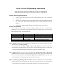
1
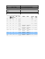
Speed Controller Programming Instructions
20A/30A/40A/45A/60A/70A/80A/100A/125A/200A
Phrases 1 Enter programming Mode
1.
Connect your motor and receiver to the speed controller, but do not connect the
battery yet.
2.
Turn on your transmitter and move the throttle stick to the full throttle position (full
up). Please Note: Most Futaba transmitters have the throttle channel reversed by
default.
3.
Connect your battery and the controller will initialize with a musical tone.
Phrases 2 Programming
After 3 seconds, the controller will start beeping a sequence of tones – a musical tone
followed by one or more beeps. Each sequence represents a parameter that you can program
and is repeated 3 times. The parameters are:
—
—.—
—.—.—
————
—————
——————
Tone + 1 Beep
Tone + 2 Beeps
Tone + 3 Beeps
Tone + 4 Beeps
Tone + 5 Beeps
Tone + 6 Beeps
Cell Type and No. of Cells
Throttle Setting
Brake Setting /Throttle type (for Heli)
Direction and Cutoff Type
Timing Mode
Pulse Width Modulation (PWM)
Step 1. Starting. When you hear the sequence for the parameter you wish to program, move the
throttle stick to the center position.
The controller will then start beeping a Morse code sequence of short and long beeps
representing the possible options you may choose for the selected parameter. See table 2 for
a list of all programmable options. Each option sequence is repeated 3 times.
Step 2. Select and save, the select the option, move the throttle stick back to the full up
position., When you hear the sequence for the option you wish to select. The controller will
then save the selected option, and sound a long beep as a confirmation. It then goes back
to the beginning of the programming sequence (phrases 2 step 1).
Step 3. Complete programming and save options. Setup all the parameters you need to change.
When complete, move the throttle stick to the lowest (down) position. The controller will
save all options and re-initialize in normal running mode so you can start your motor.
The table below summarizes the various programming options for each parameter:
A- Aircraft
B- Helicopter
A: Options for Aircraft
1.1 For (2S-7S)-ESC--Cell Type and Number
of Cells
• — 1 Short + 1 Long
• — — • 1 Short + 2 Long + 1 Short
• — • — 1 Short + 1 Long + 1 Short + 1 Long
• — • • 1 Short + 1 Long + 2 Short
• • — — 2 Short + 2 Long
• • — • 2 Short + 1 Long + 1 Short
1.2 For (4S-8S) ESC--Cell Type and Number
of Cells
• — 1 Short + 1 Long
• — — • 1 Short + 2 Long + 1 Short
• — • — 1 Short + 1 Long + 1 Short + 1 Long
• — • • 1 Short + 1 Long + 2 Short
• • — — 2 Short + 2 Long
• • — • 2 Short + 1 Long + 1 Short
1.3 For (6S-10s) ESC --Cell Type and
Number of Cells
• — 1 Short + 1 Long
• — — • 1 Short + 2 Long + 1 Short
• — • — 1 Short + 1 Long + 1 Short + 1 Long
• — • • 1 Short + 1 Long + 2 Short
• • — — 2 Short + 2 Long
• • — • 2 Short + 1 Long + 1 Short
2. Throttle Setting
•• — 2 Short + 1 Long
•• — — 2 Short + 2 Long
•• — — — 2 Short + 3 Long
•• — — — — 2 Short + 4 Long
3. Brake Setting
••• — 3 Short + 1 Long
••• — — 3 Short + 2 Long
••• — — — 3 Short + 3 Long
••• — — — — 3 Short + 4 Long
4. Direction and Cutoff Type
NiMh/NiCD Auto Cell Count - 0.8V/Cell
Cutoff Voltage
7S Li-Po (25.9V) – 21V Cutoff Voltage
6S Li-Po (22.2V) –18V Cutoff Voltage
5S Li-Po (18.5V) – 15V Cutoff Voltage
4S Li-Po (14.8V) – 12V Cutoff Voltage
3S Li-Po (11.1V) – 9V Cutoff Voltage
2S Li-Po (7.4V) – 8V Cutoff Voltage
NiMh/NiCD Auto Cell Count - 0.8V/Cell
Cutoff Voltage
8S Li-Po (29.6V) – 24V Cutoff Voltage
7S Li-Po (25.9V) – 21V Cutoff Voltage
6S Li-Po (22.2V) – 18V Cutoff Voltage
5S Li-Po (18.5V) – 15V Cutoff Voltage
4S Li-Po (14.8V) – 12V Cutoff Voltage
NiMh/NiCD Auto Cell Count - 0.8V/Cell
Cutoff Voltage
10S Li-Po (37V) – 30V Cutoff Voltage
9S Li-Po (33.3V) – 27V Cutoff Voltage
8S Li-Po (29.6V) – 24V Cutoff Voltage
7S Li-Po (25.9V) – 21V Cutoff Voltage
6S Li-Po (22.2V) – 18V Cutoff Voltage
Auto Throttle Range *
1.1ms to 1.8ms
Hard start*
Soft start
No Brake
Soft Brake*
Medium Brake
Hard Brake
•••• — 4 Short + 1 Long
Clockwise Rotation *
•••• — — 4 Short + 2 Long
Counterclockwise Rotation
•••• — — — 4 Short + 3 Long
Soft Cutoff
•••• — — — — 4 Short + 4 Long
Hard Cutoff *
5. Timing Mode Setting
••••• — 5 Short + 1 Long
••••• — — 5 Short + 2 Long
••••• — — — 5 Short + 3 Long
••••• — — — — 5 Short + 4 Long
6. Pulse Width Modulation (PWM) Setting
•••••• — 6 Short + 1 Long 8KHz
•••••• — — 6 Short + 2 Long 16KHz
1º - For 2-4 Pole Inrunner Motors *
7º - For 6-8 Pole Motors
15º- For 10-14 Pole Outrunner Motors
30º - For 10-14 Pole High-RPM Outrunner
Motors
– For low RPM and low pole count motors *
– For most out runner motors
B: Options for Helicopter
1.1 For (2S-6S)-ESC--Cell Type and Number
of Cells
• — 1 Short + 1 Long
• — — • 1 Short + 2 Long + 1 Short
• — • — 1 Short + 1 Long + 1 Short + 1 Long
• — • • 1 Short + 1 Long + 2 Short
• • — — 2 Short + 2 Long
• • — • 2 Short + 1 Long + 1 Short
1.2 For (4S-8S) ESC--Cell Type and Number
of Cells
• — 1 Short + 1 Long
• — — • 1 Short + 2 Long + 1 Short
• — • — 1 Short + 1 Long + 1 Short + 1 Long
• — • • 1 Short + 1 Long + 2 Short
• • — — 2 Short + 2 Long
• • — • 2 Short + 1 Long + 1 Short
1.3 For (6S-10s) ESC --Cell Type and
Number of Cells
• — 1 Short + 1 Long
NiMh/NiCD Auto Cell Count - 0.8V/Cell
Cutoff Voltage
6S Li-Po (22.2V) –18V Cutoff Voltage
5S Li-Po (18.5V) – 15V Cutoff Voltage
4S Li-Po (14.8V) – 12V Cutoff Voltage
3S Li-Po (11.1V) – 9V Cutoff Voltage
2S Li-Po (7.4V) – 8V Cutoff Voltage
NiMh/NiCD Auto Cell Count - 0.8V/Cell
Cutoff Voltage
8S Li-Po (29.6V) – 24V Cutoff Voltage
7S Li-Po (25.9V) – 21V Cutoff Voltage
6S Li-Po (22.2V) – 18V Cutoff Voltage
5S Li-Po (18.5V) – 15V Cutoff Voltage
4S Li-Po (14.8V) – 12V Cutoff Voltage
• — — • 1 Short + 2 Long + 1 Short
• — • — 1 Short + 1 Long + 1 Short + 1 Long
• — • • 1 Short + 1 Long + 2 Short
• • — — 2 Short + 2 Long
• • — • 2 Short + 1 Long + 1 Short
NiMh/NiCD Auto Cell Count - 0.8V/Cell
Cutoff Voltage
10S Li-Po (37V) – 30V Cutoff Voltage
9S Li-Po (33.3V) – 27V Cutoff Voltage
8S Li-Po (29.6V) – 24V Cutoff Voltage
7S Li-Po (25.9V) – 21V Cutoff Voltage
6S Li-Po (22.2V) – 18V Cutoff Voltage
2. Throttle Setting
•• — 2 Short + 1 Long
•• — — 2 Short + 2 Long
•• — — — 2 Short + 3 Long
•• — — — — 2 Short + 4 Long
Auto Throttle Range
1.1ms to 1.8ms
Hard start
Soft start
3. Throttle Type
••• — 3 Short + 1 Long
••• — — 3 Short + 2 Long
••• — — — 3 Short + 3 Long
••• — — — — 3 Short + 4 Long
Normal *
Governor Mode with 2-4 poles motors
Governor Mode with 6-10 poles motors
Governor Mode with 12-14 poles motors
4. Direction and Cutoff Type
•••• — 4 Short + 1 Long
Clockwise Rotation
•••• — — 4 Short + 2 Long
Counterclockwise Rotation
•••• — — — 4 Short + 3 Long
Soft Cutoff
•••• — — — — 4 Short + 4 Long
Hard Cutoff
5. Timing Mode Setting
••••• — 5 Short + 1 Long
••••• — — 5 Short + 2 Long
••••• — — — 5 Short + 3 Long
••••• — — — — 5 Short + 4 Long
1º - For 2-4 Pole Inrunner Motors
7º - For 6-8 Pole Motors
15º- For 10-14 Pole Outrunner Motors
30º - For 10-14 Pole High-RPM Outrunner Motors
6. Pulse Width Modulation (PWM)
Setting
•••••• — 6 Short + 1 Long 8KHz
•••••• — — 6 Short + 2 Long 16KHz
– For low RPM and low pole count motors
– For most outrunner motors
Electronics Speed Controllers Specification
BEC Input
Cons- Max
Current
Curren
t
4-10NIMH
15A
1A
10A
10A
TIMING
PWM
Weight
(G)
11//6
Size
24x17x5
2-3LIPO
20A
20A
25A
2A
4-10NIMH
18//11
32x24x7
23//14
45X24X9
2-3LIPO
30A
30A
40A
2A
4-10NIMH
~2-3LIPO
45A
45A
60A
NO
65A
65A 80A
NO
100A LV
100A
150A
NO
Programmable
- 1/7/15/30
programmable
- 8/16K
43//34
46X35X8
~2-7LIPO
618NIMH
Programmable
- 1/7/15/30
programmable
- 8/16K
55//45
55x35X8 programmable
- 1/7/15/30
programmable
- 8/16K
67//56
55X35X15
programmable
- 1/7/15/30
programmable
- 8/16K
63//54
77X53X8
programmable
- 1/7/15/30
programmable
- 8/16K
78//62
77X53X13
6-18NIMH
~2-7LIPO
12-18NIMH
~4-7LIPO
80A HV
80A
100A
NO
16-32NIMH
~6-10LIPO
100A
-HV
100A
125A
NO
12-32NIMH
~6-10LIPO