1
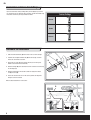
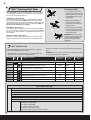
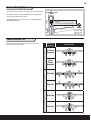
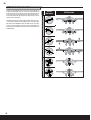
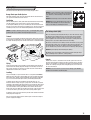
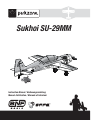
Sukhoi SU-29MM Instruction Manual / Bedienungsanleitung Manuel d’utilisation / Manuale di Istruzioni EN NOTICE All instructions, warranties and other collateral documents are subject to change at the sole discretion of Horizon Hobby, LLC. For up-to-date product literature, visit www.horizonhobby.com and click on the support tab for this product. Meaning of Special Language: The following terms are used throughout the product literature to indicate various levels of potential harm when operating this product: NOTICE: Procedures, which if not properly followed, create a possibility of physical property damage AND little or no possibility of injury. CAUTION: Procedures, which if not properly followed, create the probability of physical property damage AND a possibility of serious injury. WARNING: Procedures, which if not properly followed, create the probability of property damage, collateral damage, and serious injury OR create a high probability of superficial injury. WARNING: Read the ENTIRE instruction manual to become familiar with the features of the product before operating. Failure to operate the product correctly can result in damage to the product, personal property and cause serious injury. This is a sophisticated hobby product. It must be operated with caution and common sense and requires some basic mechanical ability. Failure to operate this Product in a safe and responsible manner could result in injury or damage to the product or other property. This product is not intended for use by children without direct adult supervision. Do not use with incompatible components or alter this product in any way outside of the instructions provided by Horizon Hobby, LLC. This manual contains instructions for safety, operation and maintenance. It is essential to read and follow all the instructions and warnings in the manual, prior to assembly, setup or use, in order to operate correctly and avoid damage or serious injury. WARNING AGAINST COUNTERFEIT PRODUCTS: If you ever need to replace your Spektrum product found in a Horizon Hobby product, always purchase from Horizon Hobby, LLC. or a Horizon Hobby authorized dealer to ensure authentic high-quality Spektrum product. Horizon Hobby, LLC. disclaims all support and warranty with regards, but not limited to, compatibility and performance of counterfeit products or products claiming compatibility with DSM or Spektrum. Age Recommendation: Not for children under 14 years. This is not a toy. Safety Precautions and Warnings As the user of this product, you are solely responsible for operating in a manner that does not endanger yourself and others or result in damage to the product or the property of others. • Always keep a safe distance in all directions around your model to avoid collisions or injury. This model is controlled by a radio signal subject to interference from many sources outside your control. Interference can cause momentary loss of control. • Always operate your model in open spaces away from full-size vehicles, traffic and people. • Always carefully follow the directions and warnings for this and any optional support equipment (chargers, rechargeable battery packs, etc.). • Always keep all chemicals, small parts and anything electrical out of the reach of children. 2 • Always avoid water exposure to all equipment not specifically designed and protected for this purpose. Moisture causes damage to electronics. • Never place any portion of the model in your mouth as it could cause serious injury or even death. • Never operate your model with low transmitter batteries. • Always keep aircraft in sight and under control. • Always use fully charged batteries. • Always keep transmitter powered on while aircraft is powered. • Always remove batteries before disassembly. • Always keep moving parts clean. • Always keep parts dry. • Always let parts cool after use before touching. • Always remove batteries after use. • Always ensure failsafe is properly set before flying. • Never operate aircraft with damaged wiring. • Never touch moving parts. EN Table of Contents Control Direction Test ...................................................................................... 9 AS3X Control Direction Test........................................................................... 10 Flying Tips .................................................................................................... 11 Guidlines for Flying 3D .................................................................................. 12 Motor Service ............................................................................................... 13 Troubleshooting Guide SAFE ......................................................................... 13 Troubleshooting Guide .................................................................................. 14 Limited Warranty .......................................................................................... 15 Warranty and Service Contact Information .................................................... 15 Compliance Information for the European Union ............................................ 16 Replacement Parts........................................................................................ 62 Optional Parts ............................................................................................... 63 Transmitter and Receiver Binding.................................................................... 4 Battery Installation and ESC Arming ................................................................ 4 Landing Gear Installation ................................................................................ 5 Wing Installation ............................................................................................. 5 Control Horn and Servo Arm Settings .............................................................. 6 Horizontal Tail Installation ............................................................................... 6 Control Surface Centering ............................................................................... 7 Trimming ........................................................................................................ 7 Transmitter Setup ........................................................................................... 7 Dual Rates and Expos ..................................................................................... 7 SAFE™ Technology Flight Modes ..................................................................... 8 Center of Gravity (CG) ..................................................................................... 9 Box Contents CG Quick Start Reference 82mm Flight Timer Stetting Trimming 3.23 inches back from the leading edge of the wing at the root. First Flight 5 Min. 7 Min. Only trim this aircraft in AS3X® Precision Flight Mode. Specifications 44.0 inches (1120mm) BNF Basic Motor 10-size BL10 brushless outrunner, 1250Kv (EFLM7225) 42.3 inches (1074mm) 4 Servos (EFLR7155) ESC 40-Amp Switch-Mode BEC Brushless ESC (EFLA1040LB) Receiver Spektrum AR636 6-Channel Sport Receiver Recommended Battery 11.1V 3S 2200mAh 30C Li-Po (EFLB22003S30) Recommended Battery Charger 2- to 3-Cell DC Li-Po Balancing Charger (PKZ1040) Recommended Transmitter Full-Range 4-Channel (or more) 2.4GHz with Spektrum™ DSM2®/DSMX® technology. (DX6 or DX6I minimum) 9 Preflight Checklist 1. Read this instruction manual thoroughly. 2. Remove and inspect the contents. 3. Charge the flight battery. 4. Fully assemble the model. 5. Install the flight battery in the aircraft (once it has been fully charged). 6. Bind the aircraft to your transmitter. 7. Make sure the linkages move freely. 8. Perform the Control Direction Test with the transmitter. 9. Perform the AS3X Control Direction Test with the aircraft. 10. Adjust the flight controls and transmitter. 11. Perform a radio system Range Check. 12. Find a safe and open area. 13. Plan flight for flying field conditions. Weight: 40.6 oz (1150 g) with battery 9 Post Flight Checklist 1. Disconnect the flight battery from the ESC (Required for Safety and battery life). 2. Power OFF the transmitter. 3. Remove the flight battery from the aircraft. 4. Recharge the flight battery. 5. Repair or replace all damaged parts. 6. Store the flight battery apart from the aircraft and monitor the battery charge. 7. Make note of the flight conditions and flight plan results, planning for future flight. To register your product online, visit www.parkzone.com 3 EN Transmitter and Receiver Binding 9 Binding Procedure Reference Table IMPORTANT: The included AR636 receiver has been programmed for operation in only this aircraft. 1. Refer to your transmitter instructions for binding to a receiver. For a list of compatible DSM2/DSMX transmitters, please visit www.bindnfly.com. 3. Make sure the transmitter controls are at neutral, the throttle is in the low position and the aircraft is immobile. * 2. Ensure the transmitter is powered off. 4. Install a bind plug in the receiver bind port. 5. Connect the flight battery in the aircraft, then power on the ESC switch. The ESC will produce a series of sounds. One long tone, then three short tones confirm that the LVC is set for the ESC. CAUTION: When using a Futaba® transmitter with a Spektrum DSM® module, you must reverse the throttle channel and rebind. Refer to your Spektrum module manual for binding and failsafe instructions. Refer to your Futaba transmitter manual for instructions on reversing the throttle channel. 6. The receiver LED will begin to flash rapidly. 7. Power on the transmitter while holding the transmitter bind button or switch. Bind Plug Installation 8. When the receiver binds to the transmitter, the light on the receiver will turn solid and the ESC will produce a series of three ascending tones. The tones indicate the ESC is armed, provided the throttle stick and throttle trim are low enough to trigger arming. 9. Remove the bind plug from the bind port. 10. Safely store the bind plug. 11. The receiver should retain the binding instructions received from the transmitter until another binding is done. Failsafe If the receiver loses transmitter communication, the failsafe will activate. When activated, the airplane controls return to the neutral position established during step 3 of the binding procedure. * The throttle will not arm if the transmitter’s throttle control is not put at the lowest position. If you encounter problems, follow the binding instructions and refer to the transmitter troubleshooting guide for other instructions. If needed, contact the appropriate Horizon Product Support office. Battery Installation and ESC Arming Battery Selection • We recommend the E-flite® 2200mAh 11.1V 3S 30C Li-Po (EFLB22003S30). • If using another battery, the battery must be at least a 2200mAh 25C battery. • Your battery should be approximately the same capacity, dimensions and weight as the E-flite Li-Po battery to fit in the fuselage without changing the center of gravity a large amount. A 1. Lower the throttle and throttle trim to the lowest settings. Power on the Transmitter, then wait 5 seconds. 2. Push the button (A) into the fuselage and remove the battery hatch. 3. Install the fully charged battery (B) all the way to the front of the battery compartment. See the Adjusting the Center of Gravity instructions for more information. 4. Make sure the flight battery is secured using the hook and loop strap (C). 5. Connect the battery to the ESC. C 6. Power on the ESC Switch (D). Keep the aircraft immobile and away from wind for 5 seconds or the system will not initialize. • The ESC will sound a series of tones (refer to step 5 of the binding instructions for more information). • An LED will light on the receiver. If the ESC sounds a continuous double beep after the flight battery is connected, recharge or replace the battery. 7. After the SAFE™ system initializes, the control surfaces will move back and forth, then come to neutral to indicate the SAFE system has initialized and is ready to operate. 8. Reinstall the battery hatch. Push the rear of the battery hatch securely to ensure the latch is fully engaged. 4 D B EN Landing Gear Installation B 1. Install the landing gear strut (A) as shown. A 2. Install the U-cover (B) on the fuselage. 3. Install the fairings (C) on the strut. 4. Secure the landing gear assembly by using 4 screws (D). Tip: Carefully support the aircraft while installing or removing screws. Disassemble in reverse order. D 2 X 10mm (4) C Wing Installation 1. Slide the wing tube (A) into the fuselage. CAUTION: DO NOT crush or otherwise damage the wiring when attaching the wing to the fuselage. 2. Install the left and right wing (B and C) over the wing tube and into the wing slot of the fuselage while inserting the aileron servo connectors through the provided holes. B 3. Invert the fuselage so the landing gear is facing up. Secure the left and right wings to the fuselage using the included screws (D). 4. Remove the canopy (E) from the fuselage. A Tip: If needed, use hemostats or pliers to pull the servo connectors into the fuselage. 5. Connect the aileron servos from the wings to the Y-harness connectors in the fuselage. The left and right aileron servos can be connected to either side of the Y-harness. 6. Replace the canopy. Disassemble in reverse order. IMPORTANT: Correct operation of the AS3X system requires connection of both ailerons to the included Y-harness and the AILE channel of the receiver. D C 3 X 22mm (2) 5 EN Control Horn and Servo Arm Settings Fly the aircraft at these factory settings. After your first flights, if you desire a less responsive feel, only adjust the rates for aileron, elevator and rudder using the dual rate function of your computerized transmitter. Factory Settings Elevator Rudder Ailerons Horizontal Tail Installation 1. Slide the horizontal tail tube (A) into the hole in the rear of the fuselage. 2. Install the left and right horizontal tails (B) onto the fuselage as shown. Ensure the control horn faces down. B 3. Apply 4 pieces of tape (C) to the fuselage mounts (one on the top and bottom of each half of the horizontal tail). 4. Attach the linkage (D) to the outermost hole in the elevator servo arm using the link keeper (E). A 5. Attach the ball link (F) to the elevator control horn using the included nut (G) and screw (H). 6. Ensure the elevator servo arm is in the correct position, then adjust the linkage to center the elevator. C When needed, disassemble in reverse order. D F E H 6 G EN Control Surface Centering Tip: Use needle-nose pliers or ball link pliers (RVO1005) to remove or install a link on a control horn. IMPORTANT: Perform the Control Direction Test before performing control surface centering. • Turn the linkage clockwise or counterclockwise until the control surface is centered. Control Surface Centering and Adjusting a Linkage While AS3X® technology is inactive (before advancing the throttle), mechanically center the control surfaces. • Attach the linkage to the servo arm or control horn after adjustment. After binding a transmitter to the airplane’s receiver, set the trims and subtrims to 0, ensure the servo arms are in the correct positions, then adjust the linkages to center the control surfaces. Trimming IMPORTANT: Only trim this aircraft in AS3X Precision Flight Mode. 2 Seconds After adjusting transmitter trim in the air or on the ground, do not touch the control sticks for 2 seconds. This allows the receiver to learn the correct settings to optimize AS3X performance. Failure to do so could affect flight performance. Transmitter Setup IMPORTANT: The included AR636 receiver has been programmed for operation in only this aircraft. A DSM2/DSMX four-channel (or better) transmitter with dual rates is required for flying this aircraft. The Spektrum™ DX6i, DX6, DX7s, DX8, DX9, DX10t, DX18 and JR® X9503, 11X or 12X transmitters may be used. A DSM2/DSMX computerized transmitter with adjustable dual rates and expo is recommended for the best flight performance of this aircraft. Transmitters DX6i and Above Servo travel ......................................................................................100% Always leave servo travel at 100%. Although the flight modes are factory set, it is strongly recomended that dual rates and expo are also used to further reduce control sensitivity for first flights. If you are a less experienced pilot we strongly recommend adjusting rates and expo to these settings. 9 Transmitter Setup Checklist Before binding your Computerized Transmitter (DX6i, DX6, DX7/DX7se, DX7s, DX8, DX9, DX10t, DX18): 1. Choose a blank model memory with only default (zero) settings (including trim and sub-trim). After binding: 1. Check and adjust the servos so each arm’s neutral position is perpendicular or as close to 90° as possible (loosen and adjust the servo arm splines on the servo only when needed). DO NOT use sub-trims to make fine adjustments, off-center sub-trim will affect servo travel and AS3X operation. Take first flights in low rate. Dual Rates and Expos High Rate Expo Low Rate Expo Aileron 100% 0% 50% 15% 3. Set rates in the transmitter as recommended. Elevator 100% 0% 100% 20% CAUTION: For safe operation, always re-bind the airplane after setup is complete to ensure the failsafe is updated with the latest setup. Rudder 100% 0% 40% 15% 2. Adjust linkage lengths so the control surfaces center when the servo arm is close to perpendicular. 7 EN SAFE™ Technology Flight Modes Panic Recovery Mode • If you feel you have lost control in any mode, hold the Panic Recovery button and reduce throttle. The SAFE technology will return the aircraft to upright flight. The included AR636 receiver has been programmed for operation in only this aircraft, providing the following selectable flight modes. The programming in this receiver cannot be changed by the user. Stagility™ Mode: Switch position 0 This mode delivers agile response, with the important addition of automatic recovery from any attitude. Release BOTH sticks and the aircraft returns to upright, flight. Releasing only one stick will not provide automatic recovery. Use this mode for slow flying and 3D maneuvers such as Harrier Rolls. Flying at high speed in this mode will cause oscillation. • Always fly at a safe altitude, as Panic Recovery may cause the aircraft to lose some altitude when leveling the wings. AS3X 3D Mode: Switch position 1 This mode uses high rates and high gains to deliver extreme maneuverability with maximum stability at low airspeeds. Use this mode for slow flying and 3D maneuvers such as Hovers and Harriers. Flying at high speed in this mode will cause oscillation. • Release the Panic Recovery button to turn off Panic mode and return to the current SAFE flight mode with full stick control again. AS3X Precision Mode: Switch position 2 This mode uses low rates and low gains to deliver precise response at high airspeeds. Use this mode to trim the aircraft and fly fast precision maneuvers. IMPORTANT: If the aircraft is upside down when the Panic Recovery button is pressed, sufficient altitude is required for the aircraft to return to upright flight. SAFE™ Transmitter Setup If using any DSM2/DSMX transmitter, the radio will have to be configured correctly for the SAFE system to work properly. *Refer to your transmitter’s manual for more information about transmitter setup. • SAFE Flight mode is selected using Channel 5 signal (high, middle, low) • Panic mode is selected with Channel 6 signal (high, low) IMPORTANT: A transmitter with a 2-position channel 5 switch will only allow the use of position 0 or position 2 flight modes. Transmitter Gear/ Ch 5 Aux 1 Flight Mode/ Panic Switch SAFE Flight Modes Panic Recovery SAFE Flight Mode Supported Switch Switch Throttle, Aileron, Elevator and Rudder are in Normal position. DX6i R N *(Flap System) Norm 100 Land 100 DX6 N R *(Channel Input Config) Gear is B, Aux1 is switch i DX7 N N DX7s N DX8 N 2 pos / 3-pos Flaps GEAR / F MODE 3 pos Bind / i B *(Flap System) Norm 100 Mid 100 Land 100 (3 pos Aux1 switch–0 & 1 are normal 2 is panic 2 pos Flaps GEAR R *(Switch Select) Gear to INH, FM to INH, Flap to Gear, Trainer to Aux1 3 pos Trainer Flaps R *(Switch Select) Gear to INH, FM to Gear, Flap to INH, Trainer to Aux 1 3 pos Trainer F MODE DX9 N R *(Channel Input Config) Gear is B, Aux1 is switch i 3 pos Bind / i B DX10t N R *(Channel Input Config) Gear is A, Aux1 is R stick 3 pos R-Stick A DX18 N R *(Channel Input Config) Gear is B, Aux1 is switch i 3 pos Bind / i B N = Normal R = Reverse DX6i 3 flight modes setup 1. Go to the SETUP LIST MENU DX6i 2. Set MODELTYPE: ACRO 3. Set REVERSE: Gear Channel 4. Go to ADJUST LIST MENU 5. Set TRAVEL ADJ: Gear/Fmode (0) 100%; Gear/Fmode (1) 40% 6. Set FLAPS: Norm 100; LAND 100 7. Set MIX 1: ACT; Gear Gear ACT, RATE D 0%; U + 100%, SW MIX, TRIM INH Resulting in: The Gear and Mix switches operate the 3 SAFE modes Gear 0; Mix 0 = Stagility™ Mode Gear 1; Mix 0 = AS3X 3D Mode Gear 1; Mix 1 = AS3X Precision Mode The Flap switch operates Panic Recovery: Position 0=Off, Position 1=On. (not a momentary switch) 8 EN Center of Gravity (CG) The CG location is 82mm back from the leading edge of the wing at the root. For first flights, install the recommended flight battery all the way forward. Secure the battery with the strap as shown. Aircraft CG and weight is based on an E-flite 11.1V 2200mAh 30C battery (EFLB22003S30) installed. 82mm 3.23 inches back from the leading edge of the wing at the root. Control Direction Test Move the controls on the transmitter to make sure the aircraft control surfaces move in the proper direction. Aileron Elevator Transmitter Command Aircraft Reaction Up Elevator Command Down Elevator Command Stick Right Stick Left Rudder Stick Right Stick Left 9 EN AS3X Control Direction Test Rudder Aileron The AS3X system will not activate until the throttle stick or trim is increased for the first time after the flight battery is connected and the ESC switch is in the ON position. Once the AS3X is active, the control surfaces may move rapidly on the aircraft. This is normal. AS3X will remain active until the battery is disconnected or the ESC switch is in the OFF position. Aircraft movement Elevator Perform the Control Direction Test to ensure the aircraft responds correctly to your transmitter. Once you are sure the aircraft responds correctly, move the aircraft as shown to ensure the AS3X system moves the control surfaces in their proper direction. If the control surfaces do not respond as shown, do not fly the aircraft. Refer to the receiver manual for more information. 10 AS3X Reaction EN Flying Tips Consult local laws and ordinances before choosing a flying location. Range Check your Radio System After final assembly, range check the radio system with the aircraft. Refer to your specific transmitter instruction manual. NOTICE: If a crash is imminent, reduce the throttle and trim fully. Failure to do so could result in extra damage to the airframe, as well as damage to the ESC and motor. NOTICE: Crash damage is not covered under warranty. Oscillation Once the AS3X system is active (after advancing the throttle for the first time), you will normally see the control surfaces react to aircraft movement. In some flight conditions you may see oscillation (the aircraft rocks back and forth on one axis due to overcontrol). If oscillation occurs, decrease airspeed. If oscillation persists, refer to the Troubleshooting Guide for more information. NOTICE: Fast flight in 3D Mode (switch position 1) and Stagility Mode (switch position 0) will cause oscillation and may damage the aircraft. Takeoff Place the aircraft in position for takeoff (facing into the wind). Select low rates for first takeoff and gradually increase the throttle to 3/4 to full and steer with the rudder. Pull back gently on the elevator and climb to a comfortable altitude. nd Wi NOTICE: When you are finished flying, never leave the aircraft in direct sunlight or in a hot, enclosed area such as a car. Doing so can damage the foam. Always decrease throttle at propeller strike. Low Voltage Cutoff (LVC) When a Li-Po battery is discharged below 3V per cell, it will not hold a charge. The ESC protects the flight battery from over-discharge using Low Voltage Cutoff (LVC). Before the battery charge decreases too much, LVC removes power supplied to the motor. Power to the motor pulses, showing that some battery power is reserved for flight control and safe landing. Disconnect and remove the Li-Po battery from the aircraft after use to prevent trickle discharge. Charge your Li-Po battery to about half capacity before storage. During storage, make sure the battery charge does not fall below 3V per cell. LVC does not prevent the battery from over-discharge during storage. Fly in this area NOTICE: Repeated flying to LVC will damage the battery. 600 feet (182 Tip: Monitor your aircraft battery’s voltage before and after flying by using a Li-Po Cell Voltage Checker (EFLA111, sold separately). .8 m ) Stand here Repairs Flying Fly the aircraft and trim it for level flight in Precision Mode (switch position 2) at 3/4 throttle. After landing, adjust the linkages mechanically to account for trim changes and then reset the trims to neutral. Ensure the aircraft will fly straight and level with no trim or sub-trim. Thanks to the Z-Foam™ construction of this aircraft, repairs to the foam can be made using virtually any adhesive (hot glue, regular CA, epoxy, etc). When parts are not repairable, see the Replacement Parts List for ordering by item number. For a listing of all replacement and optional parts, refer to the list at the end of this manual. NOTICE: Use of CA accelerant on your aircraft can damage paint. DO NOT handle the aircraft until accelerant fully dries. Landing For your first flights, set your transmitter timer or a stopwatch to 5 minutes. Adjust your timer for longer or shorter flights once you have flown the model. If the motor pulses, land the aircraft immediately and recharge the flight battery. It is not recommended to fly the battery to Low Voltage Cutoff (LVC). To land the aircraft, fly the aircraft down to the ground using 1/4 –1/3 throttle to allow for enough energy for a proper flare. The aircraft is easiest to land doing a wheel landing (two point), where the aircraft touches down on the main landing gear first while the tailwheel is still off the ground. The aircraft can also be landed in a three-point attitude, where all three wheels touch down at the same time. When the aircraft touches down, reduce back pressure on the elevator stick to prevent the plane from becoming airborne again. If landing on grass, it is best to hold full up elevator after touchdown and when taxiing to prevent nosing over. Once on the ground, avoid sharp turns until the plane has slowed enough to prevent scraping the wingtips. 11 EN Guidlines for Flying 3D Getting Started This aircraft and its SAFE™ system were designed together to help an intermediate pilot apply standard flying skills to the demands of 3D flying. The calmer the wind conditions, the easier it is to execute maneuvers. Select the SAFE flight mode that supports the maneuver you want to perform. Hold the panic recovery button to help you escape difficulty in a maneuver. You may want to fly low airspeed, high rate maneuvers at an altitude that allows you space to escape into forward flight. For your first hover attempts, fly with the canopy toward you for easier orientation. When you fly 3D, manage your throttle smoothly, but quickly respond to keep your model in the air and oriented the direction you want. If desired, use spotters to keep others from distracting you. Advanced 3D maneuvers always seem to attract a curious audience. You may want to master the Harrier first, an essential maneuver used to enter and exit other 3D maneuvers. Building Your Skills Advanced 3D Maneuvers Increasing your skills takes time. Practice regularly and try following a plan for increasing your skills. Mastering one maneuver at a time may be more beneficial than trying to learn everything all at once. Always stay aware of your aircraft’s performance in different conditions and attitudes: Harrier: What response can you consistently get from your aircraft? • Set up your aircraft for consistent response in all attitudes and flight conditions where you choose to fly. Not all challenges are due to the equipment, just as not all challenges are due to the pilot’s skills. Hover: • If you feel you reach a plateau in your skills, see if you have built the right habits in the fundamentals of 3D flying. Play to your strengths and the strengths of your aircraft while minimizing reliance on areas of weakness. • Know yourself and your equipment well enough so you can confidently take on greater challenges. Push yourself, but avoid pushing past your aircraft’s performance envelope. • Seek fun ways to safely share your enjoyment of 3D flying. 12 Inverted Harrier: Torque Roll Harrier Roll: Waterfall: Inverted Waterfall: The aircraft flies forward slowly in a nose high (approximately 45º) attitude. The inverted aircraft flies forward slowly in a nose high (approximately 45º) attitude. The aircraft nose is pointed up while the prop thrust keeps the model in the air with little or no change in altitude. The aircraft hovers with little or no change in altitude while rotating left around its roll axis. The aircraft does a harrier while rotating around its roll axis. The aircraft turns over completely (360 degrees) in the pitch axis with very little forward motion or change in altitude. The inverted aircraft turns over completely (360 degrees) in the pitch axis with very little forward motion or change in altitude. EN Motor Service Disassembly CAUTION: Always disconnect the flight battery from the aircraft before removing the propeller. 1. Remove the screw (A) and spinner (B) from the collet (C). 2. Remove the spinner nut (D), propeller (E), spinner backplate (F), backplate (G) and collet from the motor shaft (H). You will need a tool to turn the spinner nut. 3. Remove the 3 screws (I) from the cowling (J). Carefully remove the cowling from the fuselage. Paint may keep the cowling attached to the fuselage. 4. Remove the 4 screws (K) from the motor mount (L) and the fuselage. 5. Disconnect the motor wires from the ESC wires. 6. Remove the 4 screws (M) and motor (N) from the motor mount. Assembly Assemble in reverse order. • Correctly align and connect the motor wire colors with the ESC wires. • The propeller size numbers (12 x 4) must face out from the motor for correct propeller operation. • A tool is required to tighten the spinner nut on the collet. • Ensure the spinner is fully connected to the spinner backplate for safe operation. Not all wiring shown. A E F B D Troubleshooting Guide Problem Oscillation Possible Cause Flying too fast in Stagility or 3D mode Flying over recommended airspeed Damaged propeller or spinner Imbalanced propeller Motor vibration Loose receiver Loose aircraft controls Worn parts Irregular servo rotation Receiver did not save trim setting Trim change when flight mode is switched Incorrect Incorrect direction settings in response to the the receiver, which can cause AS3X Control a crash Direction Test C J I N G K H L M SAFE Solution Change to Precision Mode Reduce air speed Replace propeller or spinner Balance the propeller. For more information, view John Redman’s propeller balancing video at www. horizonhobby.com Replace parts or correctly align all parts and tighten fasteners as needed Align and secure receiver in fuselage Tighten or otherwise secure parts (servo, arm, linkage, horn and control surface) Replace worn parts (especially propeller, spinner or servo) Replace servo After adjusting transmitter trim in the air or on the ground, do not touch the control sticks for 2 seconds DO NOT fly. Correct the direction settings (refer to the receiver manual), then fly 13 EN Troubleshooting Guide Problem Aircraft will not respond to throttle but responds to other controls Extra propeller noise or extra vibration Possible Cause Throttle not at lowest position or throttle trim too high Throttle servo travel is lower than 100% Make sure throttle servo travel is 100% or greater Throttle channel is reversed Motor disconnected from ESC Damaged propeller and spinner, collet or motor Reverse throttle channel on transmitter Make sure motor is connected to the ESC Replace damaged parts Propeller is out of balance Prop nut is too loose Spinner is not tight or fully seated in place Reduced flight time Flight battery charge is low or aircraft underpow- Propeller installed backwards ered Flight battery damaged Flight conditions may be too cold Battery C rating is too low Aircraft will not Bind Transmitter too near aircraft during binding process (during binding) to transmitter Aircraft or transmitter is too close to large metal object, wireless source or another transmitter The bind plug is not installed correctly in the bind port Flight battery/Transmitter battery charge is too low Bind switch or button not held long enough during bind process ESC is powered off Transmitter too near aircraft during connecting process Aircraft will not connect (after binding) to transmitter Aircraft or transmitter is too close to large metal object, wireless source or another transmitter Bind plug left installed in bind port Aircraft bound to different model memory (ModelMatchTM radios only) Flight battery/Transmitter battery charge is too low Transmitter may have been bound using different DSM protocol ESC is powered off Control surface does Control surface, control horn, linkage or servo damage not move Wire damaged or connections loose Aircraft control surfaces do not move after switch is turned on Controls reversed Motor power pulses then motor loses power 14 Solution Reset controls with throttle stick and throttle trim at lowest setting Balance or replace propeller Tighten the prop nut Tighten the spinner or remove the spinner and turn it 180 degrees Completely recharge flight battery Install propeller with numbers facing forward Replace flight battery and follow flight battery instructions Make sure battery is warm before use Replace battery or use battery with correct C rating Move powered transmitter a few feet from aircraft, disconnect and reconnect flight battery to aircraft Move aircraft and transmitter to another location and attempt binding again Install bind plug in bind port and bind the aircraft to the transmitter Replace/recharge batteries Power off transmitter and repeat bind process. Hold transmitter bind button or switch until receiver is bound Power on the ESC switch Move powered transmitter a few feet from aircraft, disconnect and reconnect flight battery to aircraft Move aircraft and transmitter to another location and attempt connecting again Rebind transmitter to the aircraft and remove the bind plug before cycling power Select correct model memory on transmitter Replace/recharge batteries Bind aircraft to transmitter Power on the ESC switch Replace or repair damaged parts and adjust controls Do a check of wires and connections, connect or replace as needed Transmitter is not bound correctly or the incorrect model was selected Re-bind or select correct model in transmitter Flight battery charge is low BEC (Battery Elimination Circuit) of the ESC is damaged ESC is powered off Aircraft was moving during initialization Fully recharge flight battery Replace ESC Power on the ESC switch Keep aircraft still during initialization Transmitter settings are reversed Perform the Control Direction Test and adjust the controls on transmitter appropriately ESC uses default soft Low Voltage Cutoff (LVC) Recharge flight battery or replace battery that is no longer performing Weather conditions might be too cold Battery is old, worn out, or damaged Battery C rating might be too small Postpone flight until weather is warmer Replace battery Use recommended battery EN Limited Warranty What this Warranty Covers Horizon Hobby, LLC. (“Horizon”) warrants to the original purchaser that the product purchased (the “Product”) will be free from defects in materials and workmanship at the date of purchase. What is Not Covered This warranty is not transferable and does not cover (i) cosmetic damage, (ii) damage due to acts of God, accident, misuse, abuse, negligence, commercial use, or due to improper use, installation, operation or maintenance, (iii) modification of or to any part of the Product, (iv) attempted service by anyone other than a Horizon Hobby authorized service center, (v) Product not purchased from an authorized Horizon dealer, or (vi) Product not compliant with applicable technical regulations. OTHER THAN THE EXPRESS WARRANTY ABOVE, HORIZON MAKES NO OTHER WARRANTY OR REPRESENTATION, AND HEREBY DISCLAIMS ANY AND ALL IMPLIED WARRANTIES, INCLUDING, WITHOUT LIMITATION, THE IMPLIED WARRANTIES OF NON-INFRINGEMENT, MERCHANTABILITY AND FITNESS FOR A PARTICULAR PURPOSE. THE PURCHASER ACKNOWLEDGES THAT THEY ALONE HAVE DETERMINED THAT THE PRODUCT WILL SUITABLY MEET THE REQUIREMENTS OF THE PURCHASER’S INTENDED USE. Purchaser’s Remedy Horizon’s sole obligation and purchaser’s sole and exclusive remedy shall be that Horizon will, at its option, either (i) service, or (ii) replace, any Product determined by Horizon to be defective. Horizon reserves the right to inspect any and all Product(s) involved in a warranty claim. Service or replacement decisions are at the sole discretion of Horizon. Proof of purchase is required for all warranty claims. SERVICE OR REPLACEMENT AS PROVIDED UNDER THIS WARRANTY IS THE PURCHASER’S SOLE AND EXCLUSIVE REMEDY. Limitation of Liability HORIZON SHALL NOT BE LIABLE FOR SPECIAL, INDIRECT, INCIDENTAL OR CONSEQUENTIAL DAMAGES, LOSS OF PROFITS OR PRODUCTION OR COMMERCIAL LOSS IN ANY WAY, REGARDLESS OF WHETHER SUCH CLAIM IS BASED IN CONTRACT, WARRANTY, TORT, NEGLIGENCE, STRICT LIABILITY OR ANY OTHER THEORY OF LIABILITY, EVEN IF HORIZON HAS BEEN ADVISED OF THE POSSIBILITY OF SUCH DAMAGES. Further, in no event shall the liability of Horizon exceed the individual price of the Product on which liability is asserted. As Horizon has no control over use, setup, final assembly, modification or misuse, no liability shall be assumed nor accepted for any resulting damage or injury. By the act of use, setup or assembly, the user accepts all resulting liability. If you as the purchaser or user are not prepared to accept the liability associated with the use of the Product, purchaser is advised to return the Product immediately in new and unused condition to the place of purchase. Law These terms are governed by Illinois law (without regard to conflict of law principals). This warranty gives you specific legal rights, and you may also have other rights which vary from state to state. Horizon reserves the right to change or modify this warranty at any time without notice. WARRANTY SERVICES Questions, Assistance, and Services Your local hobby store and/or place of purchase cannot provide warranty support or service. Once assembly, setup or use of the Product has been started, you must contact your local distributor or Horizon directly. This will enable Horizon to better answer your questions and service you in the event that you may need any assistance. For questions or assistance, please visit our website at www.horizonhobby.com, submit a Product Support Inquiry, or call the toll free telephone number referenced in the Warranty and Service Contact Information section to speak with a Product Support representative. Inspection or Services If this Product needs to be inspected or serviced and is compliant in the country you live and use the Product in, please use the Horizon Online Service Request submission process found on our website or call Horizon to obtain a Return Merchandise Authorization (RMA) number. Pack the Product securely using a shipping carton. Please note that original boxes may be included, but are not designed to withstand the rigors of shipping without additional protection. Ship via a carrier that provides tracking and insurance for lost or damaged parcels, as Horizon is not responsible for merchandise until it arrives and is accepted at our facility. An Online Service Request is available at http:// www.horizonhobby.com/content/_service-center_render-service-center. If you do not have internet access, please contact Horizon Product Support to obtain a RMA number along with instructions for submitting your product for service. When calling Horizon, you will be asked to provide your complete name, street address, email address and phone number where you can be reached during business hours. When sending product into Horizon, please include your RMA number, a list of the included items, and a brief summary of the problem. A copy of your original sales receipt must be included for warranty consideration. Be sure your name, address, and RMA number are clearly written on the outside of the shipping carton. NOTICE: Do not ship LiPo batteries to Horizon. If you have any issue with a LiPo battery, please contact the appropriate Horizon Product Support office. Warranty Requirements For Warranty consideration, you must include your original sales receipt verifying the proof-of-purchase date. Provided warranty conditions have been met, your Product will be serviced or replaced free of charge. Service or replacement decisions are at the sole discretion of Horizon. Non-Warranty Service Should your service not be covered by warranty, service will be completed and payment will be required without notification or estimate of the expense unless the expense exceeds 50% of the retail purchase cost. By submitting the item for service you are agreeing to payment of the service without notification. Service estimates are available upon request. You must include this request with your item submitted for service. Non-warranty service estimates will be billed a minimum of ½ hour of labor. In addition you will be billed for return freight. Horizon accepts money orders and cashier’s checks, as well as Visa, MasterCard, American Express, and Discover cards. By submitting any item to Horizon for service, you are agreeing to Horizon’s Terms and Conditions found on our website http://www.horizonhobby.com/ content/_service-center_render-service-center. ATTENTION: Horizon service is limited to Product compliant in the country of use and ownership. If received, a non-compliant Product will not be serviced. Further, the sender will be responsible for arranging return shipment of the un-serviced Product, through a carrier of the sender’s choice and at the sender’s expense. Horizon will hold non-compliant Product for a period of 60 days from notification, after which it will be discarded. Warranty and Service Contact Information Country of Purchase United States of America Horizon Hobby Horizon Service Center (Repairs and Repair Requests) Horizon Product Support (Product Technical Assistance) Sales United Kingdom Germany France China Service/Parts/Sales: Horizon Hobby Limited Horizon Technischer Service Sales: Horizon Hobby GmbH Service/Parts/Sales: Horizon Hobby SAS Service/Parts/Sales: Horizon Hobby – China Phone Number/Email Address Address servicecenter.horizonhobby.com/RequestForm/ www.quickbase.com/db bghj7ey8c?a=GenNewRecord 888-959-2305 [email protected] 888-959-2305 [email protected] +44 (0) 1279 641 097 [email protected] +49 (0) 4121 2655 100 [email protected] +33 (0) 1 60 18 34 90 [email protected] +86 (021) 5180 9868 4105 Fieldstone Rd Champaign, Illinois, 61822 USA Units 1–4 , Ployters Rd, Staple Tye Harlow, Essex, CM18 7NS, United Kingdom Christian-Junge-Straße 1 25337 Elmshorn, Germany 11 Rue Georges Charpak 77127 Lieusaint, France Room 506, No. 97 Changshou Rd. Shanghai, China 200060 15 EN FCC Infromation This device complies with part 15 of the FCC Rules. Operation is subject to the following two conditions: (1) This device may not cause harmful interference, and (2) this device must accept any interference received, including interference that may cause undesired operation. IC Infromation This device complies with Industry Canada licence-exempt RSS standard(s). Operation is subject to the following two conditions: (1) this device may not cause interference, and (2) this device must accept any interference, including interference that may cause undesired operation of the device. Compliance Information for the European Union Declaration of Conformity (in accordance with ISO/IEC 17050-1) Instructions for disposal of WEEE by users in the European Union No. HH2014051801 Product(s): Item Number(s): Equipment class: Sukhoi SU-29MM BNF Basic PKZ8050 1 The object of declaration described above is in conformity with the requirements of the specifications listed below, following the provisions of the European R&TTE Directive 1999/5/EC and EMC Directive 2004/108/EC: EN301 489-1 V1.9.2: 2012 EN301 489-17 V2.1.1: 2009 EN55022:2010 + AC:2011 EN55024:2010 Signed for and on behalf of: Horizon Hobby, LLC Champaign, IL USA May 18, 2014 16 Robert Peak Chief Financial Officer Horizon Hobby, LLC This product must not be disposed of with other waste. Instead, it is the user’s responsibility to dispose of their waste equipment by handing it over to a designated collections point for the recycling of waste electrical and electronic equipment. The separate collection and recycling of your waste equipment at the time of disposal will help to conserve natural resources and ensure that it is recycled in a manner that protects human health and the environment. For more information about where you can drop off your waste equipment for recycling, please contact your local city office, your household waste disposal service or where you purchased the product. Replacement Parts • Ersatzteile • Pièces de rechange • Pezzi di ricambio Part # | Nummer Numéro | Codice Description Beschreibung Description PKZ8002 Decal Set: SU-29MM Dekorbogen: SU-29MM Planche de décalcomanies : SU-29MM Foglio con decalcomanie: SU-29MM PKZ8008 Spinner: SU-29MM Spinner: SU-29MM Cône : SU-29MM PKZ8006 Main gear set: SU-29MM Fahrwerksset: SU-29MM Jambes de train principal : SU-29MM Set ingranaggio principale: SU-29MM PKZ8021 Wing Tube: SU-29MM Flächenverbinder: SU-29MM Clé d’aile : SU-29MM Tubo ala: SU-29MM PKZ8005 Hatch and Canopy SU-29MM Kabinenhaube u. Klappe: SU-29MM Verrière avec trappe : SU-29MM Portello e capottina: SU-29MM PKZ8025 Horizontal Stab: SU-29MM Höhenruder: SU-29MM Stabilisateur : SU-29MM Stabilizzatore orizzontale: SU-29MM PKZ8022 Pushrod set: SU-29MM Gestängeset: SU-29MM Set de tringleries : SU-29MM Set rinvii di comando: SU-29MM Ogiva: SU-29MM PKZ8067 Bare Fuse: SU-29MM PKZ8020 Wing Set: SU-29MM PKZ8026 Rudderw/tail wheel: SU-29MM Leitwerk m. Spornrad: SU-29MM Roues et roulette : SU-29MM Timone con ruotino di coda: SU-29MM PKZ8013 Cowl: SU-29MM Parkzone SU-29MM Motorhaube: SU29MM Capot : SU-29MM Capottina motore: SU-29MM PKZ6528 Motor mount: VisionAire Support moteur : VisionAire Supporto del motore: VisionAire EFLM7225 BL10 Motor: VisionAire Moteur BL10 : VisionAire Motore BL10: VisionAire EFLM72252 Prop Adapter: VisionAire Adaptateur d’hélice : VisionAire Adattatore elica: VisionAire EFLA1040LB 40-Amp Lite Pro Switch-Mode BEC Brushless ESC (V2) Motorbefestigung: VisionAire Parkzone VisionAire BL10 Motor: VisionAire Parkzone VisionAire Propeller Adapter: VisionAire E-flite 40-Amp Lite Pro Switch-Mode BEC Brushless Regler (V2) Contrôleur Brushless 40A Lite Pro Switch mode BEC V2 Regolatore 40-Amp Pro Switch-Mode BEC Brushless ESC (V2) AR636 Sukhoi SU-29MM Replace- Sukhoi SU-29MM: Ersatzempfänger Récepteur de rechange : Sukhoi SU-29MM Ricevitore di ricambio: Sukhoi SU29MM EFLP12040E Propeller: 12 x 4E Propeller: 12 x 4E Hélice 12x4E Elica: 12x4E EFLR7155 13 g Digital Micro Servo E-flite 13g Digital Micro Servo Micro servo digital 13g Micro servo digitale 13g BL10 Motor Shaft: VisionAire Parkzone VisionAire BL10 Motorwelle: VisionAire Axe de moteur BL10 Albero motore BL10: VisionAire SPMAR636SU ment Receiver EFLM72251 62 Parkzone SU-29MM Rumpf o. Einbauten: Fuselage nu : SU-29MM SU-29MM Parkzone SU-29MM Tragflächenset: Aile : SU-29MM SU-29MM Descrizione Solo fusoliera: SU-29MM Set ala: SU-29MM Optional Parts • Optionale Bauteile • Pièces optionnelles • Pezzi opzionali Part # | Nummer Numéro | Codice Description Beschreibung Description Descrizione EFLA250 Park Flyer Tool Assortment, 5 pc E-flite Park Flyer Werkzeugsortiment; 5 teilig Assortiment d'outils park flyer, 5pc Park Flyer assortimento attrezzi, 5 pc EFLAEC302 EC3 Battery Connector (2) E-flite EC3 Akkukabel, Buchse (2) Prises EC3 coté batterie (2) Connettore batteria EFLAEC303 ite EC3 Kabelsatz, Stecker/ EC3 Device/Battery Connector E-fl Buchse Prises EC3 coté contrôleur (2) Connettore batteria/dispositivo RVO1005 Ball Link Pliers EFLB22003S30 11.1V 3S 30C 2200MAH Li-Po 11.1V 3S 30C 2200mAh LiPo 11.1V 3S 30C 2200MAH Li-Po PKZ1029 11.1V 3S 25C 2200MAH Li-Po 11.1V 3S 25C 2200mAh LiPo 11.1V 3S 25C 2200MAH Li-Po EFLA111 Li-Po Cell Voltage Checker E-flite Li-Po Cell Volt Checker DYNC2010 Contrôleur de tension Li-Po Chargeur-équilibreur CC Li-Po 2–3 2-3 DC Lipo balancing charger 2-3 DC Lipo-Balancer-Ladegerät cellules Prophet Sport Plus 50W AC DC Dynamite Ladegerät Prophet Sport Chargeur Prophet Sport Plus 50W Charger Plus 50W AC/DC EU AC DC DYN1405 Li-Po Charge Protection Bag, Large Dynamite LiPoCharge Protection Bag groß Sac de charge Li-Po, grand modèle Busta protezione grande par LiPo DYN1400 Li-Po Charge Protection Bag, Small Dynamite LiPoCharge Protection Bag klein Sac de charge Li-Po, petit modèle Busta protezione piccola par LiPo DX6i DSMX 6-Channel Transmitter Spektrum DX6i DSMX 6-Kanal Sender Emetteur DX6i DSMX 6 voies DX6i DSMX Trasmettitore 6 canali DX6 DSMX 6-Channel Transmitter Spektrum DX6 DSMX 6-Kanal Sender Emetteur DX6 DSMX 6 voies DX6 DSMX Trasmettitore 6 canali DX7s DSMX 7-Channel Transmitter Spektrum DX7s DSMX 7 Kanal Sender Emetteur DX7s DSMX 7 voies DX7s DSMX Trasmettitore 7 canali DX8 DSMX 8-Channel Transmitter Spektrum DX8 DSMX 8 Kanal Sender Emetteur DX8 DSMX 8 voies DX8 DSMX Trasmettitore 8 canali DX9 DSMX 9-Channel Transmitter Spektrum DX9 DSMX 9 Kanal Sender Emetteur DX9 DSMX 9 voies DX9 DSMX Trasmettitore 9 canali DX18 DSMX 18-Channel Transmitter Spektrum DX18 DSMX 18 Kanal Sender Emetteur DX18 DSMX 18 voies DX18 DSMX Trasmettitore 18 canali PKZ1040 Revolution Deluxe Kugelkopfzange Pince à rotules Pinze per attacchi a sfera 11.1V 3S 30C 2200MAH Li-Po 11.1V 3S 25C 2200MAH Li-Po Controllo tensione batteria LiPo Caricabatteria con bilanciatore per 2 o 3 celle Li-Po Prophet Sport Plus 50W AC DC Caricabatterie 63 © 2014 Horizon Hobby, LLC. ParkZone, E-flite, Prophet, SAFE, the SAFE logo, AS3X, EC3, DSM, DSM2, DSMX, Z-Foam, the BNF logo, and ModelMatch are trademarks or registered trademarks of Horizon Hobby, LLC. The Spektrum trademark is used with permission of Bachmann Industries, Inc. JR is a registered trademark of JR Americas. Futaba is a registered trademark of Futaba Denshi Kogyo Kabushiki Kaisha Corporation of Japan. All other trademarks, service marks and logos are property of their respective owners. www.parkzone.com PKZ8050 Created 08/14 42459.2