1
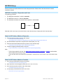
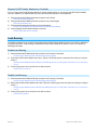
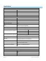
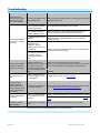
On/Off Outdoor Module
Owner’s Manual
2634-222
Page 1 of 13
2634-222 - Rev: 1/21/2014 7:45 AM
TABLE OF CONTENTS
About On/Off Outdoor Module................................................................................................................................... 3
Features and Benefits ............................................................................................................................................... 3
Before Installation ....................................................................................................................................................... 4
Installation ................................................................................................................................................................... 4
Using On/Off Outdoor Module ................................................................................................................................... 5
Local Control Operation ............................................................................................................................................ 5
LED Activity ............................................................................................................................................................... 5
Adjust Local Settings ................................................................................................................................................. 5
LED On or Off ............................................................................................................................................................ 5
Blink on Traffic ........................................................................................................................................................... 5
Programming Lock .................................................................................................................................................... 5
INSTEON Setup ........................................................................................................................................................... 6
INSTEON Controllers, Responders and Links .......................................................................................................... 6
Make On/Off Outdoor Module a Responder ............................................................................................................. 6
Make On/Off Outdoor Module a Controller ............................................................................................................... 6
Groups ....................................................................................................................................................................... 7
Scenes....................................................................................................................................................................... 7
Remove On/Off Outdoor Module as a Responder .................................................................................................... 7
Remove On/Off Outdoor Module as a Controller ...................................................................................................... 8
Load Sensing............................................................................................................................................................... 8
Enable Load Sensing ................................................................................................................................................ 8
Disable Load Sensing ............................................................................................................................................... 8
Specifications .............................................................................................................................................................. 9
Troubleshooting ........................................................................................................................................................ 11
Phase Bridge Detect Beacon/RF Range Test......................................................................................................... 12
Factory Reset .......................................................................................................................................................... 12
Certification and Warranty ....................................................................................................................................... 13
Certification.............................................................................................................................................................. 13
FCC and Industry Canada Compliance Statement ................................................................................................. 13
ETL/UL Warning (Safety Warning) .......................................................................................................................... 13
Limited Warranty ..................................................................................................................................................... 13
Page 2 of 13
2634-222 - Rev: 1/21/2014 7:45 AM
About On/Off Outdoor Module
On/Off Outdoor Module is a simple way to remotely control any plug-in device, in or outside your home, at the touch
of a button. Send commands to On/Off Outdoor Module from any INSTEON controller, or link it to other INSTEON
devices as a controller.
Set
button
Status
LED
Outlet
Features and Benefits
-
Installs and links to other INSTEON devices in minutes
-
Controls standard incandescent loads up to 1800 Watts and inductive loads up to 15 Amps
-
Weatherproof to withstand harsh outdoor conditions
-
Indicates INSTEON setup mode activity and operational states with a dual-color Status LED and beeper
-
Load Sensing easily enabled and disabled
-
Stores setup state in memory so settings aren’t lost during power outages
-
Two-year warranty
In the Box
On/Off Outdoor Module
Quick Start Guide
Page 3 of 13
Optional Accessories
Mini Remote
INSTEON Hub
2634-222 - Rev: 1/21/2014 7:45 AM
Before Installation
CAUTIONS AND WARNINGS
Read and understand these instructions before installing and retain them for future reference.
On/Off Outdoor Module is intended for installation in accordance with the National Electric Code and local regulations in the United States or the
Canadian Electrical Code and local regulations in Canada.
On/Off Outdoor Module is not designed nor approved for use on power lines other than 120V 60Hz, single phase. Attempting to use On/Off
Outdoor Module on non-approved power lines may have hazardous consequences.
Prior to installing On/Off Outdoor Module, please review the entire installation procedure and take the following precautions:
-
Be sure On/Off Outdoor Module is connected to a 3-prong AC outlet that includes a Ground Fault Circuit Interrupt (GFCI) feature. If On/Off
Outdoor Module is plugged into an outlet without GFCI protection, make sure there is a GFCI device upstream (at another outlet closer to
the electrical panel or a GFCI circuit breaker).
-
Test your GFCI protection each time On/Off Outdoor Module is plugged in, as well as on a monthly basis. To test your GFCI protection,
make sure On/Off Outdoor Module is plugged in and the connected load is on. Then, push the TEST button on the GFCI outlet or circuit
breaker. This unit must stop operating. Wait about 5 seconds and then push the RESET button on the GFCI outlet or circuit breaker. On/Off
Outdoor Module will begin receiving electricity and the connected load will turn on. If the GFCI circuit does not perform in this manner, there
may be an electrical malfunction, increasing the probability of electric shock. Disconnect the power until the problem has been corrected.
Please see the instructions that came with your GFCI device for specific testing procedures. When in doubt of the GFCI device’s ability to
detect a ground fault, replace the GFCI device.
-
Don’t bury On/Off Outdoor Module, any electrical cable, or component connected to it. A buried power cord may result in electrocution if
improper cables are used or if digging occurs over the cable.
-
Don’t allow vegetation to grow on or around On/Off Outdoor Module
-
Don’t install On/Off Outdoor Module in a manner that allows water to accumulate around it
-
If an extension cord is used, the cord must be properly grounded. Be sure the extension cord is of adequate capacity to provide power to
your load. A “light-duty” or “medium-duty” extension cord may cause a voltage drop, which will cause overheating of the cable, plug, or
socket.
-
Don’t attempt to open On/Off Outdoor Module. The case is sealed and can’t be opened. There are no user-serviceable parts inside.
-
Don’t use On/Off Outdoor Module to control devices that preserve, maintain, or contribute to human or animal safety or life support
-
Don’t plug On/Off Outdoor Module into an outlet controlled by a switch because if the switch is inadvertently turned off, On/Off Outdoor
Module won’t have power
-
Don’t plug On/Off Outdoor Module into a filtered power strip or AC line filter
-
Be sure the device’s built-in switch is in the on position
-
Don’t exceed the load rating of On/Off Outdoor Module. Check and add up all the electrical devices that will be attached and make sure the
total does not exceed 15 Amps.
-
Don’t use any electrical cord or extension cord that is damaged or in poor condition
IMPORTANT!
If you have any difficulties or questions, consult an electrician. If you have any questions, call the INSTEON Support Line at 866-243-8022.
Installation
1) Plug appliance/device (also called the load) you want to control into On/Off Outdoor Module outlet
2) Plug On/Off Outdoor Module into unswitched wall outlet
3)
Status LED will turn on solid green
The load will turn on. (If load does not turn on, tap Set button.)
Allow On/Off Outdoor Module to hang down from outlet (see image)
Note: After completing installation, you will not be able to use the load’s built-in switch to control the load,
unless you have enabled Load Sensing. See Load Sensing.
Page 4 of 13
2634-222 - Rev: 1/21/2014 7:45 AM
Using On/Off Outdoor Module
Local Control Operation
Connected load/responders
Double-tap
Tap
Set Button
On/Off
On/Off
(instant)
LED
Green/
Red
LED Activity
LED
Status/Setup Mode
Solid green
Load is on
Solid red
Load is off
Blinking green
Linking mode
Blinking red
Unlinking mode
Adjust Local Settings
LED On or Off
Default = On
This setting is only adjustable via software or a central controller. When enabled, LED On will cause the LED to be
green when the Load is on and Red when the load is off.
Blink on Traffic
Default = enabled
This setting is only adjustable via software or a central controller. On/Off Outdoor Module LED will blink green for
INSTEON traffic and if it detects noise that could disrupt communication.
Programming Lock
Default = disabled
This setting is only adjustable via software or a central controller. When enabled, Programming Lock will disable the
set button so that a user can not adjust settings or modify links. This is typically used in commercial or installer
applications.
Page 5 of 13
2634-222 - Rev: 1/21/2014 7:45 AM
INSTEON Setup
Some products have subtle differences in their setup procedures. Please refer to the other devices’ owner’s
manuals for details.
INSTEON Controllers, Responders and Links
Let’s define a few terms.
•
The INSTEON “transmitter” is called a controller
•
The INSTEON “receiver” is called a responder
•
The association between the controller and responder is called a link
Link
Controller
Responder
Note that a link is one way. If you wish to have control “the other way,” simply add a link “the other way.”
Make On/Off Outdoor Module a Responder
1) Press and hold controller set button until it beeps
Controller LED will start blinking
You will have four minutes to complete the next steps before linking mode times out
2) Use On/Off Module set button to adjust load to desired state (on or off)
3) Press and hold On/Off Outdoor Module set button until it double-beeps
Controller will double-beep and its LED will stop blinking
4) Test link by tapping controller button on and off
Lamp connected to On/Off Outdoor Module will respond appropriately
Note:
-
The link just created is one way. See Make On/Off Outdoor Module a Controller or Groups to add another
link to keep the two products in sync.
-
If you wish the load to be off when link is activated—such as for an “all off” scene—turn off the load in step
#2.
Make On/Off Outdoor Module a Controller
1)
Press and hold On/Off Module set button until it beeps
On/Off Module LED will start blinking green
2)
Adjust responder to desired brightness state (such as on, 50% or even off)
3)
Press and hold responder set button until it double-beeps
4)
Test by tapping On/Off Module set button to turn on/off
On/Off Module LED will stop blinking
Responder will respond appropriately
Page 6 of 13
2634-222 - Rev: 1/21/2014 7:45 AM
Groups
Devices in a group share all the same settings (e.g., on-level, ramp rate). This keeps all group members
synchronized. Every device in a group is both a controller of, and responder to, all the other devices. The most
common example of a group is a 3-way lighting circuit (2 switches). For simplicity, we will assume that the desired
group level is on.
The following steps will create a virtual 3-way circuit including device “A” and device “B”:
Turn A and B on
Press and hold A set button until it beeps
A status LED will start blinking green
3) Press and hold B set button until it double-beeps
A will double-beep and its LED will stop blinking
4) Press and hold B set button until it beeps
B LED will start blinking green
5) Press and hold A set button until it double-beeps
B will double-beep and its LED will stop blinking
6) Test by turning load on and off from A and then B
The load(s) and both A and B LEDs will remain in synch
1)
2)
Scenes
Devices in a scene can each have different settings. This provides for advanced scene creation. Software is
recommended for scene management.
Example of a scene with 1 controller and On/Off Outdoor Module as a member:
1) Press and hold controller set button until it beeps
Controller LED will start blinking green
2) Tap controller set button
Controller LED will start double-blinking green
3) Use On/Off Module set button to adjust load to desired state (on or off)
4) Press and hold On/Off Outdoor Module set button until it double-beeps
5) For each additional scene member:
a) Adjust member to desired scene brightness
b) Press and hold Set button until it double-beeps
6) Tap controller set button
Controller will beep and LED will stop blinking
7) Test by tapping controller button on and off
On/Off Outdoor Module and other scene responders will all respond appropriately
Remove On/Off Outdoor Module as a Responder
If you no longer want a controller button to control On/Off Outdoor Module, follow these directions.
Note: If you ever wish to uninstall On/Off Outdoor Module, it is important that you remove all On/Off Outdoor
Module responder links. Otherwise, controllers will repetitively retry commands, creating network delays.
1) Press and hold controller button until it beeps
LED will start blinking green
2) Press and hold controller button until it beeps again
LED will start blinking red
3) Press and hold On/Off Outdoor Module set button until it double-beeps
Controller LED will stop blinking
4) Test by tapping controller button on and off
On/Off Outdoor Module will no longer respond
Page 7 of 13
2634-222 - Rev: 1/21/2014 7:45 AM
Remove On/Off Outdoor Module as a Controller
If you no longer want On/Off Outdoor Module to control another device (or are removing On/Off Outdoor Module
from your network) it is important that you follow the instructions below for each responder.
1) Press and hold On/Off Outdoor Module set button until it beeps
LED will start blinking green
2) Press and hold On/Off Outdoor Module set button until it beeps again
LED will start blinking red
3) Press and hold responder set button until it double-beeps
On/Off Outdoor Module will double-beep and LED will stop blinking
4) Test by tapping On/Off Outdoor Module on and off
Former responder will not respond
Load Sensing
Load Sensing allows you to control the load plugged into On/Off Outdoor Module from its local switch in addition to
any linked controllers. Load Sensing is disabled on On/Off Outdoor Module by default, but you can enable it by
following these steps.
Enable Load Sensing
1) Press and hold On/Off Outdoor Module set button until it beeps (3 seconds)
On/Off Outdoor Module Status LED will begin blinking green
2) Triple-tap On/Off Outdoor Module set button. (Be sure to quickly press the set button like clicking a computer
mouse.)
On/Off Outdoor Module Status LED will stop blinking and turn on solid green if the load is on or solid red if
it is off
3) Test by turning the load on and off from its built-in switch
Load will turn on and off
Disable Load Sensing
1) Press and hold On/Off Outdoor Module set button until it beeps (3 seconds)
On/Off Outdoor Module Status LED will begin blinking green
2) Double-tap On/Off Outdoor Module set button. (Be sure to quickly press the set button like clicking a computer
mouse.)
On/Off Outdoor Module Status LED will stop blinking and turn on solid green if the load is on or solid red if
it is off
3) Test by turning the load on and off from its built-in switch
Load will not respond
Page 8 of 13
2634-222 - Rev: 1/21/2014 7:45 AM
Specifications
General
Product name
On/Off Outdoor Module
Brand/manufacturer
INSTEON
Manufacturer product number
2634-222
UPC
813922013375
Warranty
2 years, limited
INSTEON
INSTEON powerline mesh repeater
Yes
INSTEON RF mesh repeater
Yes
INSTEON controller
Yes
INSTEON responder
Yes
Maximum links/scenes
400
LED
Green when load is on, red when load is off
Blinks red or green during setup
Beep on button press
No
Local control
Yes
On
Off
On
Off
Commands supported as controller
Commands supported as responder
Software configurable
RF range
Beep
Yes
Up to 150 feet open air*
*Range may vary due to local interference
Phase bridge detect beacon
Yes
INSTEON device category
0x02 switched lighting control
INSTEON device subcategory
0x38 (US – 915 MHz RF frequency)
X10
N/A
Mechanical
Mounting
Type A (US) AC Outlet
Wires
N/A
Max Cable Size
N/A
Min Cable Size
N/A
Page 9 of 13
2634-222 - Rev: 1/21/2014 7:45 AM
Screw On/Off Outdoor Module
connections
None
Case color
Dark gray
Set button
Yes
Plastic
UV stabilized polycarbonate
Beeper
Yes
LED
1, Red-Green
Dimensions
2.75"W x 4.32"H x 1.27"D (with 6" lead)
70mm W x 110mm H x 32mm D (with 150mm lead)
Weight
.465lbs (7.2 oz) .21kg
Operating environment
Indoor/outdoor
Rainproof rated
NEMA Type 3R Enclosure
Operating temperature range
-4° to 122° F
Storage temperature range
-4 to 158 F
Operating humidity range
0 - 90% relative humidity
o
o
-20° to 50° C
o
o
-20 to 70 C
Electrical
Voltage
120 Volts AC +/- 10%
Frequency
60Hz
Load type(s)
Standard appliances up to 15 Amps and incandescent lights up
to 1800 watts
Maximum load
15 Amps; 1800 Watts (for incandescent loads)
Minimum load
None
User replaceable fuse
None
Retains all settings without power
Yes, saved in non-volatile EEPROM
Standby power consumption
< 1 watt
Safety approval(s)
FCC ID
Page 10 of 13
Conforms to ANSI/UL Std. 508-2005
Certified to CAN/CSA Std. C22.2 #14-05
SBP26342
2634-222 - Rev: 1/21/2014 7:45 AM
Troubleshooting
Problem
The Status LED on
On/Off Outdoor Module
is not turning on and
won’t control the load
On/Off Outdoor Module
won’t link to or work with
a controller
Possible Cause
Solution
On/Off Outdoor Module may
not be getting power
Make sure On/Off Outdoor Module is not plugged into a switched
outlet that is turned off
The controller or might have
been reset without unlinking
On/Off Outdoor Module
Re-link On/Off Outdoor Module to the controller
The controller and On/Off
Outdoor Module may be on
opposite powerline phases
Make sure a least one other INSTEON dual-band device is
properly installed to bridge the two powerline phases.
The INSTEON signal may be
too weak.
Add additional INSTEON devices or move around existing
INSTEON devices. All INSTEON devices act as INSTEON
network repeaters.
Large appliances, such as
refrigerators or air
conditioners, may be
producing electrical noise on
the powerline
Install a power line noise filter (#1626-10) to filter electrical noise
Other electrical devices, such and minimize signal attenuation
as computers, televisions, or
power strips, may be
absorbing the INSTEON
signal
On/Off Outdoor Module
is taking a long time to
respond to a controller
The controller may be
sending commands to a
responder that is no longer in
use. Commands for the
unused responder are being
resent and loading down the
signal.
Unlink any unused responders from the controller.
HINT: If you are using home automation software, you can easily
check scene membership and eliminate unnecessary links.
If the above doesn’t work, perform a factory reset on the
controller
The load turned on by
itself
Another controller or timer
could have triggered On/Off
Outdoor Module.
Perform a factory reset. See Factory Reset.
The controller can turn
off On/Off Outdoor
Module but On/Off
Outdoor Module does
not turn on when I send
an ON command from
the controller
On/Off Outdoor Module may
be Linked at its off state.
Relink On/Off Outdoor Module to the controller, while the load is
on. See Make On/Off Outdoor Module a Responder.
On/Off Outdoor Module
is locked up
A surge or excessive noise
on the powerline may have
glitched it
Unplug On/Off Outdoor Module for 10 seconds and then reinstall
If the above doesn’t work, perform a factory reset. See Factory
Reset.
The load is not being
The load may not be getting
controlled by On/Off
Make sure the load’s built-in switch is in the on position
power
Outdoor Module
If you have tried these solutions, reviewed this Owner’s Manual, and still cannot resolve an issue you are having with On/Off
Outdoor Module, please call INSTEON Support Line at 866-243-8022.
Page 11 of 13
2634-222 - Rev: 1/21/2014 7:45 AM
Phase Bridge Detect Beacon/RF Range Test
On/Off Outdoor Module automatically bridges the electrical phases in your home (via communications with other
dual-band devices on the “other phase”). This is only important in 2-phase homes with powerline-only INSTEON
products or buildings with both 2- and 3- phase circuits. The phase bridge detect beacon can also be used as an
RF range test to see if your devices are within communication range. You will need at least one other INSTEON
dual-band device installed.
1) Quickly tap Set button four times
On/Off Outdoor Module will start beeping once per second
LED will turn solid green
2) Check the LED behavior of other dual-band devices
Phase Bridge Detect Beacon
•
If the other dual-band device is blinking green, it is on the other phase:
Device provides a phase bridge to Micro module
•
If the other dual-band device is blinking red, it is on the same phase:
Device does not provide a phase bridge to Micro module
Relocate if necessary (and practical)
•
If the other dual-band device is not blinking:
Device is not within RF range of Micro module so it does not provide a phase bridge
Relocate if necessary (and practical) or add an additional dual-band device
RF Range Test
•
RF range test: if LED is blinking:
Device is within RF communication range
•
RF range test: if LED is not blinking:
Device is not within RF communication range
Relocate if necessary (and practical) or add an additional dual-band device
3) Tap Set button
On/Off Outdoor Module will stop beeping
Other device LEDs will stop blinking
Factory Reset
All settings, links and scenes will be erased.
1) If you are using a controller to control On/Off Outdoor Module, be sure to unlink it from the controller
2) Unplug On/Off Outdoor Module
3) While pressing and holding Set button, plug On/Off Outdoor Module back in. Do not let go of set button.
On/Off Outdoor Module will begin to emit a long beep
Status LED will turn green
4) When long beep stops, release set button
Status LED will flash red and then turn green
After a few seconds, load will turn on
Page 12 of 13
2634-222 - Rev: 1/21/2014 7:45 AM
Certification and Warranty
Certification
This product has been thoroughly tested by ITS ETL SEMKO, a nationally recognized independent third-party testing laboratory. The North American ETL Listed
mark signifies that the device has been tested to and has met the requirements of a widely recognized consensus of U.S. and Canadian device safety standards,
that the manufacturing site has been audited, and that the manufacturer has agreed to a program of quarterly factory follow-up inspections to verify continued
conformance.
FCC and Industry Canada Compliance Statement
This device complies with FCC Rules Part 15 and Industry Canada RSS-210. Operation is subject to the following two conditions:
(1) This device may not cause harmful interference, and
(2) This device must accept any interference, including interference that may cause undesired operation of the device.
Le present appareil est conforme aux CNR d'Industrie Canada applicables aux appareils radio exempts de licence. L'exploitation est autorise aux deux conditions
suivantes:
(1) l'appareil ne doit pas produire de brouillage, et
(2) l'utilisateur de l'appareil doit accepter tout brouillage radiolectrique subi, mme si le brouillage est susceptible d'en compromettre le fonctionnement.
The digital circuitry of this device has been tested and found to comply with the limits for a Class B digital device, pursuant to Part 15 of the FCC Rules. These limits
are designed to provide reasonable protection against harmful interference in residential installations. This equipment generates, uses, and can radiate radio
frequency energy and, if not installed and used in accordance with the instructions, may cause harmful interference to radio and television reception. However, there
is no guarantee that interference will not occur in a particular installation. If this device does cause such interference, which can be verified by turning the device off
and on, the user is encouraged to eliminate the interference by one or more of the following measures:
- Re-orient or relocate the receiving antenna of the device experiencing the interference
- Increase the distance between this device and the receiver
- Connect the device to an AC outlet on a circuit different from the one that supplies power to the receiver
- Consult the dealer or an experienced radio/TV technician
WARNING: Changes or modifications to this device not expressly approved by the party responsible for compliance could void the user’s authority to operate the
equipment.
ETL/UL Warning (Safety Warning)
CAUTION: To reduce the risk of overheating and possible damage to other equipment, do not install this device to control a receptacle, a motor-operated appliance,
a fluorescent lighting fixture, or a transformer-supplied appliance.
Gradateurs commandant une lampe a filament de tungstene – afin de reduire le risqué de surchauffe et la possibilite d’endommagement a d’autres materiels, ne pas
installer pour commander une prise, un appareil a moteur, une lampe fluorescente ou un appareil alimente par un transformateur.
Limited Warranty
Seller warrants to the original consumer purchaser of this product that, for a period of two years from the date of purchase, this product will be free from defects in
material and workmanship and will perform in substantial conformity to the description of the product in this Owner’s Manual. This warranty shall not apply to defects
or errors caused by misuse or neglect. If the product is found to be defective in material or workmanship, or if the product does not perform as warranted above
during the warranty period, Seller will either repair it, replace it, or refund the purchase price, at its option, upon receipt of the product at the address below, postage
prepaid, with proof of the date of purchase and an explanation of the defect or error. The repair, replacement, or refund that is provided for above shall be the full
extent of Seller’s liability with respect to this product. For repair or replacement during the warranty period, call 800-762-7845 with the Model # and Revision # of the
device to receive an RMA# and send the product, along with all other required materials to:
INSTEON
ATTN: Receiving
16542 Millikan Ave.
Irvine, CA 92606-5027
Limitations
The above warranty is in lieu of and Seller disclaims all other warranties, whether oral or written, express or implied, including any warranty or merchantability or
fitness for a particular purpose. Any implied warranty, including any warranty of merchantability or fitness for a particular purpose, which may not be disclaimed or
supplanted as provided above shall be limited to the two-year of the express warranty above. No other representation or claim of any nature by any person shall be
binding upon Seller or modify the terms of the above warranty and disclaimer.
Home automation devices have the risk of failure to operate, incorrect operation, or electrical or mechanical tampering. For optimal use, manually verify the device
state. Any home automation device should be viewed as a convenience, but not as a sole method for controlling your home.
In no event shall Seller be liable for special, incidental, consequential, or other damages resulting from possession or use of this device, including without limitation
damage to property and, to the extent permitted by law, personal injury, even if Seller knew or should have known of the possibility of such damages. Some states
do not allow limitations on how long an implied warranty lasts and/or the exclusion or limitation of damages, in which case the above limitations and/or exclusions
may not apply to you. You may also have other legal rights that may vary from state to state.
Protected under U.S. and foreign patents (see www.insteon.com/patents)
© Copyright 2013 INSTEON, 16542 Millikan Ave., Irvine, CA 92606, 866-243-8022, www.insteon.com
Page 13 of 13
2634-222 - Rev: 1/21/2014 7:45 AM