1
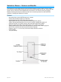
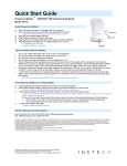
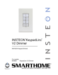
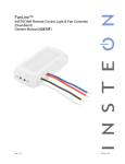
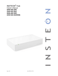
SwitchLinc™ Dimmer
INSTEON® Remote Control Dimmer Switch
Owner’s Manual (rev 5.0+)
(#2476Dxxx)
Page 1 of 21
2476D - Rev: 1/21/2014 7:15 AM
SwitchLinc Dimmer – Features and Benefits ........................................................................................... 3
Features..................................................................................................................................................... 3
What’s in the Box? ..................................................................................................................................... 4
Installing SwitchLinc .................................................................................................................................. 4
Identifying the Electrical Wires in Your Home ........................................................................................... 4
Tools Needed ............................................................................................................................................ 4
Installing SwitchLinc in a Typical 2-Way Circuit ..................................................................................... 4
Understanding Multi-Way Circuits ............................................................................................................ 5
Using SwitchLinc in Virtual Multi-Way Circuits ....................................................................................... 6
Installing Multi-Way SwitchLinc Modules................................................................................................. 7
Special Treatment for 4- or More-Way Circuits ........................................................................................ 8
Using SwitchLinc ........................................................................................................................................ 9
Paddle........................................................................................................................................................ 9
Air Gap....................................................................................................................................................... 9
Local On-Level .......................................................................................................................................... 9
Ramp Rate .............................................................................................................................................. 10
Programming SwitchLinc as Part of an INSTEON Network.................................................................. 10
Make SwitchLinc a Controller .................................................................................................................. 11
Remove SwitchLinc as a Controller ........................................................................................................ 11
Make SwitchLinc a Responder ................................................................................................................ 11
Remove SwitchLinc as a Responder ...................................................................................................... 11
Scenes ..................................................................................................................................................... 12
Power Restore ......................................................................................................................................... 12
Using SwitchLinc in an X10 Network ...................................................................................................... 12
Add an X10 Address ................................................................................................................................ 12
Remove an X10 Address......................................................................................................................... 12
Advanced X10 Programming................................................................................................................... 13
Advanced Features ................................................................................................................................... 13
Make SwitchLinc a Controller of Multiple Responders ............................................................................ 13
Remove SwitchLinc as a Controller of Multiple Responders .................................................................. 13
Groups ..................................................................................................................................................... 13
Change LED Brightness Levels .............................................................................................................. 14
Factory Reset .......................................................................................................................................... 14
Change Paddle and LED Colors ............................................................................................................. 15
Additional Resources ............................................................................................................................... 16
Specifications ............................................................................................................................................ 16
Troubleshooting ........................................................................................................................................ 18
Certification and Warranty ....................................................................................................................... 21
Certification .............................................................................................................................................. 21
FCC and Industry Canada Compliance Statement ................................................................................. 21
ETL/UL Warning (Safety Warning) .......................................................................................................... 21
Limited Warranty ..................................................................................................................................... 21
Limitations ............................................................................................................................................ 21
Page 2 of 21
2476D - Rev: 1/21/2014 7:15 AM
SwitchLinc Dimmer – Features and Benefits
Congratulations on purchasing the high-quality INSTEON SwitchLinc Dimmer Switch. With its elegant
look, smooth touch and stylish LED bar, you can not only control the lights you wire to it, but you can add
remote control to all kinds of other INSTEON and X10 devices in your home to match your lifestyle.
Besides controlling other devices, SwitchLinc itself can be remotely operated from other INSTEON
controllers, including other SwitchLinc modules.
Features
-
Quick setup links to other INSTEON devices in minutes
Controls all incandescent lights up to 600 watts
Integrated dimmer with 32 dim levels and 4 ramp rates
Rocker paddle has tap (on/off) and press-and-hold (brighten/dim) actions
LED bar indicates light brightness level and acts as a gentle nightlight when light is off
Setup state stored in non-volatile memory and preserved through power outages
Swap out default white LED bar with optional green, blue, amber or red LED kit
Change paddle and trim frame colors with optional ivory, almond, black, brown or gray kits
Wires in like a standard wall switch (neutral connection required)
Supports virtual 3-, 4- or more-way circuits with multiple SwitchLinc modules
X10 compatible
Two-year warranty
Page 3 of 21
2476D - Rev: 1/21/2014 7:15 AM
What’s in the Box?
-
SwitchLinc Dimmer
Quick Start Guide
Two (2) mounting screws
Four (4) wire nuts
Installing SwitchLinc
CAUTIONS AND WARNINGS
Read and understand these instructions before installing and retain them for future reference.
This product is intended for installation in accordance with the National Electric Code and local regulations in the United States or
the Canadian Electrical Code and local regulations in Canada. Use indoors only. This product is not designed or approved for
use on power lines other than 120V 60Hz, single phase. Attempting to use this product on non-approved power lines may have
hazardous consequences.
Recommended installation practices:
Use only indoors or in an outdoor rated box.
Be sure that you have turned off the circuit breaker or removed the fuse for the circuit you are installing this product into.
Installing this product with the power on will expose you to dangerous voltages.
Connect using only copper or copper-clad wire.
This product may feel warm during operation. The amount of heat generated is within approved limits and poses no
hazards. To minimize heat buildup, ensure the area surrounding the rear of this product is as clear of clutter as possible.
Each INSTEON product is assigned a unique INSTEON I.D., which is printed on the product’s label.
To reduce the risk of overheating and possible damage to other equipment, do not use this product to control loads in
excess of the specified maximum(s) or, install in locations with electricity specifications which are outside of the product’s
specifications. If this device supports dimming, please note that dimming an inductive load, such as a fan or transformer,
could cause damage to the dimmer, the load-bearing device or both. If the manufacturer of the load device does not
recommend dimming, use a non-dimming INSTEON on/off switch. USER ASSUMES ALL RISKS ASSOCIATED WITH
DIMMING AN INDUCTIVE LOAD.
Identifying the Electrical Wires in Your Home
-
line – carries 120VAC electricity into the wall box, may also be called hot, live or power, commonly black
neutral – returns 120VAC to power company, commonly white and in a multi-wire bundle
load – connects to light/load device, commonly black and in a separate cable jacket
ground – connection to electrical ground, commonly a bare wire, a green wire or a screw on a metal box
IMPORTANT!
If you have any difficulties or questions, consult an electrician. If you are not knowledgeable about and comfortable with electrical
circuitry, have a qualified electrician install the product for you.
Tools Needed
-
Flathead screwdriver
Wire cutter/stripper
-
Phillips screwdriver
Voltage meter
Installing SwitchLinc in a Typical 2-Way Circuit
1)
2)
3)
4)
At the circuit breaker or fuse panel, disable the circuit supplying power to the switch
Remove the faceplate from the existing switch, then unscrew the switch and pull it out from the
wall box
Disconnect the wires from the switch you are replacing and ensure you have 1/2” of bare wire on
the ends
Enable power to the switch from the circuit breaker or fuse panel, then use a line voltage meter to
correctly identify the line, load, neutral and ground wires. Turn the breaker off again. (Refer to
wiring diagram below to properly connect your wires to the INSTEON device.)
Note: Mechanical switches don’t utilize neutral wires, but they are usually available in
the back of the switch box
Page 4 of 21
Rev: 1/21/2014 7:15 AM
5)
6)
7)
8)
9)
Ensure that all wire connectors are firmly attached and that there is no exposed copper except for
the ground wire
Orient SwitchLinc with the LED bar at the left, gently place it into the wall box and screw it into
place
Enable power to the switch from the circuit breaker or fuse panel
Test that SwitchLinc is working properly by using the paddle to turn the light on and off
Reinstall the faceplate
Note: the neutral wire will not normally be connected to the switch you are replacing. If there is no neutral
wire in the box, consult an electrician or call the INSTEON Support line at 1-800-762-7845.
Understanding Multi-Way Circuits
If more than one switch controls a single set of lights (or load), the switches are part of a multi-way circuit.
A 3-way uses two switches to control one load, a 4-way circuit uses three switches and so on. Most
homes have one or more 3-way circuits, such as two switches located on opposite ends of hallways or at
two different entrances to a room. Circuits that are 4- or more-way are less common. Here is how a
typical wired-in 3-way circuit (with two switches) works:
Page 5 of 21
Rev: 1/21/2014 7:15 AM
A wired-in 4- or more-way circuit (with three or more switches) has additional switches added in the
middle of the circuit. In the diagram below, the additional switch (Switch 3+) is shown in two different
positions, since wiring can vary from home to home.
To learn more about multi-way circuits, go to your preferred Internet search engine and enter the search
terms “3-way switch” or “4-way switch.”
Using SwitchLinc in Virtual Multi-Way Circuits
You can use SwitchLinc modules to replace switches in multi-way circuits that are already wired in or to
create multi-way circuits where there is no existing wiring. These are called virtual multi-way circuits.
In a virtual multi-way circuit, only one SwitchLinc (called SwitchLinc Primary) is actually connected to and
controls the load. Any additional SwitchLinc modules (called SwitchLinc Secondaries) are only connected
to the powerline via the line and neutral wires. All SwitchLinc modules can communicate with one another
using INSTEON networking on the powerline. After wiring in SwitchLinc modules, you can create a virtual
multi-way circuit by setting up all of the modules to control each other. The diagram below shows how you
convert a wired-in 3-way circuit using two SwitchLinc modules.
Note: Actual location of SwitchLinc wires may differ with product revision or model.
Page 6 of 21
Rev: 1/21/2014 7:15 AM
•
•
•
•
Notice that the red traveler wires are not used, so they are capped off at both ends with wire nuts
o The black traveler wire (traveler 2) is converted to a line wire
o In SwitchLinc Secondary wall box, connect traveler 2 to the existing line wire and to
SwitchLinc Secondary line wire
o In the wall box at the other end of the circuit, connect traveler 2 to SwitchLinc Primary line
wire
The SwitchLinc Primary load wire is connected to the actual lights being controlled
The load wires on all SwitchLinc Secondaries will not be connected to anything, so cap them off
with wire nuts
All SwitchLinc modules—Primary and Secondaries—must be connected to neutral and ground
o SwitchLinc will not function without a neutral
o The switches you are replacing usually will not have a neutral connection
o If there is no neutral wire in the wall box, consult an electrician or call the INSTEON
Support line at 1-800-762-7845
Installing Multi-Way SwitchLinc Modules
When replacing a 3-way mechanical switch, each switch will have three wires connected to it from the
wall box. Four- or more-way circuits will have four wires connected to the switches in the center of the
circuit. For this tutorial, we will follow the most commonly used wire colors for North American homes:
Line wire (also called hot)
Neutral wire
Ground wire
Load wire
Traveler wires
1)
2)
3)
4)
5)
6)
7)
8)
9)
10)
11)
12)
Black
White wire bundle
Bare copper, green wire or
green screw
Red
Black and/or red
Disable power at the circuit breaker panel
Pull all the switches in the multi-way circuit out of their wall boxes. Each switch should have at
least three wires connected to it, depending on whether it is a 3-way, 4-way or more-way circuit.
Unscrew the wires from the old switches. If the wires cannot be
Fig. 1
unscrewed, cut the wires where they enter the switch and strip ½” of bare
insulation off the ends.
Turn the electricity back on
Make sure the wires are not touching anything. They are not
grounded and could cause an electrical shock.
Fig. 2
Using a voltage meter, individually test and identify each wire (see Fig. 1)
The wire measuring 120VAC is the line wire (usually black)
Turn the electricity back off
Connect the wall box line wire and black traveler wire to SwitchLinc
Secondary line wire. Cap all three wires together with a
Fig. 3
wire nut (see Fig. 2).
Cap wall box red traveler wire with a wire nut
Cap SwitchLinc Secondary red load wire with a wire nut
Locate the neutral wires (usually a white wire bundle) in the rear of the wall
box. Connect SwitchLinc Secondary white neutral wire to the box neutral
wires with a wire nut (see Fig. 3)
Fig. 4
Connect SwitchLinc Secondary bare copper ground wire to the wall box
ground wires with a wire nut (see Fig. 4)
If necessary, install additional SwitchLinc Secondaries by repeating steps
7-11. See Special Treatment for 4- or More-Way Circuits at the end of this
section for more information.
Page 7 of 21
Rev: 1/21/2014 7:15 AM
13)
14)
15)
16)
17)
18)
19)
20)
In the wall box where you will install SwitchLinc Primary, identify the load wire (usually red). This
is the wire that carries power from the switch to the load.
Identify the black traveler wire. If you are unsure, repeat steps 3-6 to measure the voltage and
find the wire measuring 120VAC. This is the wire connected to the line wire in step 7.
Make sure the electricity is turned off before proceeding
Connect SwitchLinc Primary black line wire to the wall box black traveler wire with a wire nut (see
Fig. 2)
Cap the wall box’s red traveler wire with a wire nut
Connect SwitchLinc Primary red load wire to the wall box load wire with a wire nut
Connect SwitchLinc Primary white neutral wire to the box neutral wires with a wire nut (see Fig. 3)
Connect SwitchLinc Primary bare copper ground wire to the wall box ground wires with a wire nut
(see Fig. 4)
Refer to step 6 in Installing SwitchLinc in a Typical 2-Way Circuit to complete installation
Special Treatment for 4- or More-Way Circuits
If your lighting circuit includes more than two switches controlling a single set of lights, those extra
switches will have four wires connected to them. Two of the wires are travelers from the preceding switch,
while the other two are travelers to the next switch in the chain. You will convert the black traveler wires to
line wires and replace the old 4-wire switches with SwitchLinc Secondaries.
Page 8 of 21
Rev: 1/21/2014 7:15 AM
1)
2)
3)
4)
5)
Connect SwitchLinc Secondary black line wire to the wall box black traveler wire with a wire nut
Cap the two unused traveler wires (usually red) with wire nuts
Cap SwitchLinc Secondary red load wire with a wire nut
Connect SwitchLinc Primary white neutral wire to the box neutral wires with a wire nut (see Fig. 3)
Connect SwitchLinc Primary bare copper ground wire to the wall box ground wires with a wire nut
(see Fig. 4)
Using SwitchLinc
Paddle
Like any rocker switch, the paddle top turns on the load while the bottom turns it off. The load’s behavior
changes depending on whether you tap, double-tap or press and hold the paddle.
Paddle
Tap
Double-Tap
Press and Hold
Top
Ramp to local on-level
Instant full-on
Brighten
Bottom
Ramp to full-off
Instant full-off
Dim
Air Gap
Anytime you need SwitchLinc’s controlled circuit to be unpowered but don’t want to turn off the circuit
breaker—such as when replacing light bulbs—use the air gap to quickly and conveniently disable power
to the switch.
Using your fingernail or a small flathead screwdriver, pull out SwitchLinc Set button as far as it will go
(about 1/8”). This opens the mechanical contacts and removes all power from SwitchLinc and its load.
(Because SwitchLinc’s settings are stored in its non-volatile memory, your setup information will not be
lost.) To re-enable power to SwitchLinc, simply push in the Set button until it is flush with the trim frame.
Local On-Level
The local on-level is the brightness setting at which the connected load will turn on. While SwitchLinc
Dimmer’s default on-level is 100% brightness, it is adjustable anywhere from off to 100%.
1) Press and hold SwitchLinc Set button until it beeps
SwitchLinc status LED will blink green
2) Press and hold SwitchLinc Set button until it beeps again
SwitchLinc status LED will blink red
3) Press and hold SwitchLinc Set button until it beeps a third time
SwitchLinc status LED will blink green
4) Press and hold SwitchLinc Set button until it beeps a fourth time
SwitchLinc status LED will blink red
5) Tap SwitchLinc Set button
SwitchLinc will beep
Status LED will double-blink red
6) Use SwitchLinc’s paddle to adjust the connected load(s) to the designed brightness level
Press and hold the paddle top or bottom to gradually brighten/dim the light(s)
Press and hold the paddle bottom to gradually dim the light(s)
Release paddle when you reach the desired brightness level
7) Press and hold SwitchLinc Set button until it beeps
8) Test the local on-level by tapping SwitchLinc’s paddle on and off
The load connected to SwitchLinc will ramp to the local on-level
Page 9 of 21
Rev: 1/21/2014 7:15 AM
Ramp Rate
The local ramp rate is the time it takes for SwitchLinc to reach 100% brightness (from off) when controlled
at the paddle. The default ramp rate is 0.5 seconds, but it is adjustable from instant-on to 9 seconds
(using Set button) or up to 8 minutes (with software).
The ramp rate is set up using the light’s brightness level as the indicator for the ramping speed: the
brighter the light, the faster the ramp rate. Refer to this table to help you set your desired ramp rate:
Brightness Level
Ramp Rate in Seconds
90-100%
0.1
77-86%
0.2
65-74%
0.3
52-61%
2.0
39-48%
2.0
26-35%
4.5
13-23%
6.5
1-10%
8.5
1%
9.0
1) Adjust the connected light(s) to the brightness corresponding with your desired ramp rate (see table
above).
2) Quickly double-tap SwitchLinc’s Set button.
SwitchLinc will beep.
3) Test ramp rate settings but tapping SwitchLinc or controller button on and off.
The connected light(s) will turn on and off at the programmed ramp rate(s).
4) If the ramp rate is not as desired:
a. Go back to step 1 and repeat the process.
b. Your Set button double-tap in step 2 might not have been fast enough, and you may have
accidentually reprogrammed the local on-level instead.
Note: HouseLinc (and other home automation software) will allow you to set on-levels and ramp rates to
your exact specifications—it even extends the maximum ramp rate from 9 seconds to 8 minutes—and
apply them consistently to multiple devices throughout your home.
Programming SwitchLinc as Part of an INSTEON Network
SwitchLinc Dimmer can be added to an INSTEON network as both a controller and a responder.
Additionally, it can act as an Access Point to detect your home’s electrical phases and allow RF-only and
powerline-only devices to communicate with each other.
Page 10 of 21
Rev: 1/21/2014 7:15 AM
Make SwitchLinc a Controller
Follow the steps below to link SwitchLinc as a controller of another INSTEON device.
1) Press and hold SwitchLinc Set button until it beeps (about 3 seconds)
Status LED will blink green
You will have 4 minutes to complete the next steps before linking mode times out
2) Set the responder to the state you want to activate from SwitchLinc (e.g., on, 50% brightness, off)
If the responder is a multi-scene device such as a KeypadLinc, tap the scene button you want to
control so its LED illuminates
3) Press and hold the responder’s Set button for 3 seconds
SwitchLinc will double-beep and status LED will stop blinking
Responder LED will stop blinking and it may double-beep
4) Confirm that linking was successful by tapping SwitchLinc paddle on and off
The responder will respond appropriately
5) If you want SwitchLinc to control multiple responders, repeat steps 1-4 with each additional responder
or see Add Multiple Scene Responders.
Remove SwitchLinc as a Controller
If you are disabling or removing any INSTEON responders that SwitchLinc controls, it is very important
that you unlink each responder from SwitchLinc before disabling or removal. Otherwise, SwitchLinc will
repeatedly try to send commands, causing delays in your INSTEON network’s inter-device
communication.
1) Press and hold SwitchLinc Set button until it beeps (about 3 seconds)
Status LED will blink green
2) Again, press and hold SwitchLinc Set button until it beeps (about 3 seconds)
Status LED will blink red
You will have 4 minutes to complete the next step before unlinking mode times out
3) Press and hold the responder Set button for 3 seconds
SwitchLinc will double-beep and status LED will stop blinking
4) Confirm that unlinking was successful by tapping SwitchLinc paddle on and off
The responder will no longer respond
Make SwitchLinc a Responder
Follow the steps below to make SwitchLinc a responder of another INSTEON controller.
1) Press and hold the controller Set or scene button until it beeps and/or LED blinks (about 3 seconds)
If the controller is a multi-scene device such as a KeypadLinc, press and hold the scene button
you want to use as the controller
Controller LED will blink
You will have 4 minutes to complete the next step before linking mode times out
2) Use SwitchLinc to set the connected load to the state you want to activate from the controller (e.g.,
on, 50% brightness, off)
3) Press and hold SwitchLinc Set button until it double-beeps (about 3 seconds)
SwitchLinc status LED will flash once, then turn on solid
4) Confirm that linking was successful by tapping the controller button on and off
The load connected to SwitchLinc will respond appropriately
Remove SwitchLinc as a Responder
If you are going to disable or remove SwitchLinc, it is very important that you unlink it from all controllers.
Otherwise, the controllers will try sending commands to SwitchLinc, causing delays in your INSTEON
network’s inter-device communication.
Page 11 of 21
Rev: 1/21/2014 7:15 AM
1) Press and hold the controller Set or scene button until it beeps and/or LED blinks (about 3 seconds)
Controller LED will blink
2) Press and hold the controller Set or scene button until it beeps and/or LED blinks again
Controller LED will continue blinking
You will have 4 minutes to complete the next step before unlinking mode times out
3) Press and hold SwitchLinc Set button until it double-beeps
SwitchLinc status LED will flash once, then turn on solid
4) Confirm that unlinking was successful by tapping the controller button on and off
The load connected to SwitchLinc will no longer respond
Scenes
INSTEON scenes let you activate dramatic room ambiences with multiple lights and appliances. For
example, you can set all the lights in a scene to dim to 50% or turn certain lights on while turning others
off, all with the tap of a button on a controller.
INSTEON scenes are very easy to set up: just link more than one responder to the same On/Off or scene
button on a controller. Then, when you press any of the linked buttons on the controller, all of the
INSTEON devices linked in the scene will respond as a group.
To set up an INSTEON scene, you can individually link each device to a controller. Or save time and
create multiple links at once.
Power Restore
SwitchLinc stores all of its scenes, properties, etc. in its internal non-volatile memory so all settings are
retained after a power outage. Upon power being restored, SwitchLinc will return its connected load(s)
and all LEDs to their states prior to power outage.
Using SwitchLinc in an X10 Network
Like most INSTEON devices, SwitchLinc X10-ready, meaning it can both send and respond to X10
commands. However, SwitchLinc does not ship with an X10 address, so you must set one up when first
installing SwitchLinc or after performing a factory reset.
Add an X10 Address
1) Press and hold SwitchLinc Set button until it beeps (about 3 seconds)
SwitchLinc status LED will blink
You will have 4 minutes to complete the next step before linking mode times out
2) Using an X10 controller, send the X10 address you want to assign to SwitchLinc followed by the ON
command three times
For example, to assign the address A1, you would send A1-ON-A1-ON-A1-ON
3) Once SwitchLinc Dimmer has received the sequence, it will exit linking mode
SwitchLinc will double-beep
Remove an X10 Address
If you are no longer going to utilize an X10 address associated with SwitchLinc, it is very important that
you remove its X10 address. Otherwise, SwitchLinc will still listen for X10 commands (somewhat
hindering INSTEON reception) and may respond to spurious X10 “noise.” Furthermore, SwitchLinc will
transmit an X10 address and command every time the button is tapped.
1) Press and hold SwitchLinc Set button until it beeps (about 3 seconds)
Page 12 of 21
Rev: 1/21/2014 7:15 AM
SwitchLinc status LED will blink
2) Press and hold SwitchLinc Set button until it beeps again
SwitchLinc status LED will continue blinking
You will have 4 minutes to complete the next step before unlinking mode times out
3) Using an X10 controller, send the X10 address you want to remove followed by the ON command
three times
For example, to remove the address A1, you would send A1-ON-A1-ON-A1-ON
4) Once SwitchLinc has received the sequence, it will exit unlinking mode
SwitchLinc will beep.
Advanced X10 Programming
Instructions on setting X10 primary address and scene addresses can be found at
http://www.insteon.com/insteon-x10-programming.html.
Advanced Features
Make SwitchLinc a Controller of Multiple Responders
1) Press and hold SwitchLinc Set button until it beeps
SwitchLinc status LED will start blinking green
2) Tap SwitchLinc Set button
SwitchLinc status LED will double-blink green
3) For each responder you are adding:
a. Tap on/off or press and hold to adjust responder to desired state
b. Press and hold responder Set button until it beeps (or LED flashes)
SwitchLinc will double-beep
4) After all responders have been added, tap SwitchLinc Set button
SwitchLinc LED will stop blinking
5) Test by tapping SwitchLinc on and off a couple of times
All the responders added will respond
Remove SwitchLinc as a Controller of Multiple Responders
1) Press and hold SwitchLinc Set button until it beeps
SwitchLinc status LED will start blinking green
2) Press and hold SwitchLinc Set button again until it beeps again
SwitchLinc status LED will start blinking red
3) Tap SwitchLinc Set button
SwitchLinc status LED will double-blink red
4) For each responder you are removing:
a. If multi-button device, tap the responding button
b. Press and hold responder Set button until it beeps (or LED flashes)
5) Tap SwitchLinc Set button
SwitchLinc status LED will stop blinking
6) Test by tapping controller button a couple of times
All responders removed will not respond
Groups
Groups are scenes in which all members stay synchronized. Common examples include 3-way lighting
circuits and scenes with a single load-bearing device.
Example: 2-Switch Circuit
Page 13 of 21
Rev: 1/21/2014 7:15 AM
1) Link SwitchLinc as a controller of another INSTEON device. (See Make SwitchLinc a Controller.)
2) Link the same INSTEON device as a controller of SwitchLinc. (See Make SwitchLinc a Responder.)
3) Test the group by controlling the load from SwitchLinc Dimmer and the other device
The load, SwitchLinc LEDs and the other INSTEON device LEDs will remain in synch
Example: Multi-Way Circuit
Although we recommend using home automation software (such as HouseLinc) to set up multi-way circuit
groups, the following steps will also work when carefully followed.
1)
2)
3)
4)
5)
6)
7)
8)
Turn on load(s) to desired same level
Press and hold SwitchLinc Set button until it beeps
Tap SwitchLinc Set button
Initiate linking mode on secondary INSTEON device, usually by pressing and holding the Set button
for about 3 seconds
Repeat step 3 for each addition INSTEON device in the circuit
Once all INSTEON devices are in linking mode, tap SwitchLinc Set button
Repeat steps 2-6 for each device in the circuit until each has been linked as a controller and
responder of all group members
Test the group by controlling the load(s) from SwitchLinc and the other devices
Change LED Brightness Levels
SwitchLinc LEDs can be adjusted to shine brighter or dimmer, or even turned off.
1) Press and hold Set button until it beeps
SwitchLinc status LED will blink green
2) Press and hold Set button until it beeps again
SwitchLinc status LED will blink red
3) Press and hold Set button until it beeps a third time
SwitchLinc status LED will blink green
4) Tap Set button
SwitchLinc will beep and its status LED will double-blink green
5) Press and hold the paddle top/bottom to brighten/dim the LEDs to your desired brightness
6) Once LEDs are adjusted, press and hold Set button until it beeps
Factory Reset
Factory Reset clears all user settings from SwitchLinc, including INSTEON scenes, on-levels, ramp rates,
X10 addresses, etc.
1) Pull out SwitchLinc Set button to create an air gap
2) Wait 10 seconds
3) Push in Set button and hold it. Do not let go.
SwitchLinc will begin to emit a long beep
4) When beep stops, release Set button
A few seconds will pass
SwitchLinc will double-beep
LEDs will return to normal brightness
The connected load will turn on
Page 14 of 21
Rev: 1/21/2014 7:15 AM
Change Paddle and LED Colors
You can swap out the included white LEDs and/or front paddle and trim frame assembly with a colorchange kit before or after SwitchLinc is installed. During the changeover process, power and load may
remain on and operating. There are no dangerous voltages or unsafe areas under the paddle.
• LED kits available: frosted white, four color (includes red, amber, green and blue)
• Paddle kits available: almond, light almond, ivory, gray, black, brown, white
1) If SwitchLinc is already installed in the wall, remove the
wallplate from the switch wall box
2) Remove the four Phillips screws that hold the paddle
assembly to the metal frame
3) Pull the entire paddle straight away from the switch. You may
have to wiggle the bottom of the frame to get it free from the
Set button
Figure 1: Paddle assembly and SwitchLinc
body separated
4) Using a flat blade or needlenose pliers, snap the large light
pipe out of the frame (as shown in Figure 2 at right). Do the
same for the small light pipe
Figure 2: Snap out the light pipes with a
flat tool.
5) Choose which LEDs and/or paddle and trim frame you would like to install into SwitchLinc
6) Orient the new small light pipe with its protrusion facing
toward center of the new frame. Snap it into place. If placed
in backwards or reverse, it will not click into place. (Refer to
Figure 3 at right.)
7) Orient the new large light pipe with side that has the most
protrusions facing toward the center of the new frame. Using
only finger pressure, snap the light pipe into the frame.
(Refer to Figure 3 at right).
Figure 3: Insert the new light pipes with the
protrusions facing the center
8) If both light pipes are installed correctly, they will stick straight out from the back of the frame
(as shown in Figure 4, below left). If installed incorrectly, they will appear to be tilted (as shown
Page 15 of 21
Rev: 1/21/2014 7:15 AM
in Figure 5, below right).
Figure 4: LED light pipes correctly installed
Figure 5: LED light pipes incorrectly installed
9) Gently place the paddle assembly onto front of SwitchLinc. A little force may be necessary to
snap the assembly over the Set button. Reinstall four screws that you removed in step 2.
Additional Resources
Find home automation solutions, helpful tips, interactive demos, videos, user forums, and more at the
INSTEON Learning Center: www.smarthome.com/learningcenter.html
Specifications
General
Product Name
SwitchLinc Dimmer
Brand
INSTEON
Manufacturer Product Number
2476D, INSTEON SwitchLinc Dimmer
UPC
White - 2476D: 891114000082
Almond - 2476DAL: 689076406345
Light Almond - 2476DLAL: 813922011562
Black -2476DBK: 689076406444
Gray - 2476DGY: 689076406741
Ivory - 2476DIV: 689076406642
Brown - 2476DBR: 689076406543
Patent Number
U.S. Patent No. 7,345,998, International patents pending
Warranty
Two years, limited
INSTEON
INSTEON Address
1 hard-coded out of 16,777,216 possible
Maximum Scene Memberships
417
Brightness Levels
32
On-Level
4 locally, increments of 1% with software
Ramp Rate
0.1 to 2 seconds if programmed locally, 0.125 seconds to 8
minutes if programmed remotely)
Page 16 of 21
Rev: 1/21/2014 7:15 AM
Scene Commands Supported as
Controller
Scene Commands Supported as
Responder
On
Fast-on
Off
Fast-off
Dim
Brighten
On
Fast-on
Off
Fast-off
Dim
Brighten
Software Configurable
Yes
RF Range
915 MHz
X10 Support
Yes
X10 Addresses
1 optional (ships unassigned)
INSTEON Device Category
Dimmer switches
INSTEON Device Subcategory
Mechanical
Mounting
Wire Nuts
Wires
Mounts in single or multiple-ganged wall box. Control 200W
less load for each immediately adjacent SwitchLinc Dimmer
installed. For example, 600 W load control becomes 400 W
with another dimmer to the immediate right or left. Use a triplegang box with a mechanical switch in the center to avoid derating.
4 included
line (black)
load (red)
neutral (white)
ground (bare copper)
Case Color
White
Set Button
Yes
Beeper
Yes
LED
Dual-color red/green setup LED, 9 white LEDs
Dimensions
4.1" H x 1.8" W x 1.2" D
Weight
3.6 oz.
Operating Environment
Indoors
Operating Temperature Range
32°F to 104°F
Operating Humidity Range
Up to 85% relative humidity
Electrical
Voltage
120 volts AC +/- 10%, 60 Hertz, single phase
Maximum Dimmer load
600 watts (uses 12-Amp triac dimmer)
load Type(s)
Wired-in incandescent lighting devices
Retains all settings without power
Non-volatile EEPROM
Standby power consumption
0.59 watts
Page 17 of 21
Rev: 1/21/2014 7:15 AM
Certifications
Safety tested for use in USA and Canada (ETL #3017581)
Troubleshooting
Problem
Possible Cause
Solution
Make sure the circuit breaker is turned on
The LED bar on
SwitchLinc is not turning SwitchLinc is not getting
on at all and SwitchLinc power
won't control my light
The switch I'm replacing
only has two wires
SwitchLinc is not
receiving signals from
INSTEON or X10
controllers
Check wall box wires to ensure all connections
are tight and no bare wires are exposed
Check the light fixture to ensure all connections
are tight and no bare wires are exposed
SwitchLinc needs a neutral
wire in order to operate
Look in the rear of the wall box for a group of
white wires all tied together with a wire nut.
Those are the neutral wires. Connect the
neutral SwitchLinc wire there.
SwitchLinc and the controller
are on opposite powerline
phases
Make sure two Access Points (#2443) or other
dual-band INSTEON products are properly
installed to detect the two powerline phases
The controller is plugged into
a power strip
Powerline signals can't travel through power
filters. Plugging the Controller directly into a
wall outlet works best.
Other modules are loading
down the signal
Move the other modules or the controller to
another outlet
SwitchLinc is not linking
to or working with an
INSTEON controller or
device
The INSTEON signal may be
too weak
SwitchLinc doesn't
always respond to an
INSTEON controller
The INSTEON controller may
have been reset without first
unlinking SwitchLinc from it
The light turned on by
itself
Another controller, a timer or
stray X10 signals triggered
SwitchLinc
Add new INSTEON devices or move around
existing INSTEON devices. All INSTEON
devices act as INSTEON network repeaters.
Make sure you are not experiencing
interference with older X10 BoosterLinc
technology. Upgrade to INSTEON-compatible
BoosterLinc modules (#4827).
Relink SwitchLinc to the INSTEON controller.
See Adding SwitchLinc Relay as an INSTEON
Responder.
Install a powerline signal blocker in your home
to keep X10 signals from neighboring homes
from interfering. Consider not using SwitchLinc
in X10 mode.
If the above doesn't work, perform a factory
reset. See Factory Reset.
Install a powerline noise filter (such as
FilterLinc) between the load and SwitchLinc
SwitchLinc turns on, but
not off, using another
controller
The load is producing
electrical noise that is
interfering with the reception
of powerline signal
Install additional INSTEON devices to boost
the INSTEON signal
Increase the X10 signal strength with an
INSTEON-compatible X10 booster to
overcome the power line noise
Remove the X10 address from the button on
your INSTEON controller so it doesn’t send
Page 18 of 21
Rev: 1/21/2014 7:15 AM
both INSTEON and X10 commands
My light only turns off
when I tap the paddle
top on SwitchLinc, but I
can brighten and dim it
If the INSTEON device is still available, unlink it
You may have removed an
from SwitchLinc. See Removing SwitchLinc as
INSTEON device that your
an INSTEON Controller.
SwitchLinc is trying to operate
SwitchLinc is retrying the
Perform a factory reset. See Factory Reset.
missing INSTEON device
When I press the paddle
on SwitchLinc, it takes a
long time for other
INSTEON responders to
respond
You may have removed an
INSTEON device that your
SwitchLinc is trying to operate.
SwitchLinc is retrying the
missing INSTEON device
SwitchLinc doesn't
respond to X10 address
A1 when I first set it up
Unlike previous X10-only
products, SwitchLinc does not Set up an X10 address. See Adding an X10
have an X10 address set up at Address.
the factory
The load is buzzing
when on or dim
The buld filaments are vibrating. Use roughThe dimming component
service, 130V or appliance-grade bulbs to
inside SwitchLinc "chops" the reduce the noise.
powerline sine wave to reduce
Run SwitchLinc in “full-on” mode or switch to a
the power
non-dimming SwitchLinc On/Off Relay.
SwitchLinc is locked up
Pull the Set button on SwitchLinc all the way
out to create an air gap, wait 10 seconds, then
A surge or excessive noise on push it back in until it’s flush with the trim frame
the powerline may have
(don't push it all the way in).
glitched it
If the above doesn't work, perform a factory
reset. See Factory Reset.
SwitchLinc is getting
warm to the touch
SwitchLinc Dimmer will dissipate about 1W per
It is normal for wall dimmers to 100W controlled. Using metal wall boxes,
feel warm, but not hot
removing insulation around the box or
controlling a smaller load can lessen the heat.
SwitchLinc can turn off
my responder, but
nothing happens when I
send an ON command
from SwitchLinc
Your responder may be linked Relink your responder to SwitchLinc, while the
at its off state
responding device is on
If the INSTEON device is still available, unlink it
from SwitchLinc. See Removing SwitchLinc
Relay as an INSTEON Responder.
Perform a factory reset. See Factory Reset.
My controller can turn off
SwitchLinc, but
SwitchLinc does not turn SwitchLinc may be linked at its Relink SwitchLinc to your controller, while the
on when I send an ON
off state
load is on
command from my
controller
After wiring in
SwitchLinc, the unit lets
out a continuous beep
SwitchLinc trips the Arc
Fault Circuit Interrupter
(AFCI)
Turn off the circuit breaker and try reinstalling
SwitchLinc is issuing an error
SwitchLinc. If you are still experiencing an error
beep because the unit is wired
beep, consult an electrician to help you install
incorrectly
SwitchLinc.
The AFCI might be too
sensitive
Replace your AFCI with a less sensitive brand
or model from a hardware store with a
customer-friendly return policy. SwitchLinc
modules do not trip when used with the
following AFCI models:
Page 19 of 21
Rev: 1/21/2014 7:15 AM
•
•
There might be loose
connections within your
home’s wiring
GE 15 Amp Combination Arc Fault
Breaker #THQL1115AFP2
Murray 2-Pole Combination Type Arc
Fault Circuit Interrupter #MP215AFCP
Install a powerline noise filter (such as a
FilterLinc) between the output and the lead.
The status LEDS are
Dim the LEDs. See Changing the LED
The status LEDS are too
adjustable and might be set at
Brightness.
bright
the brightest level
If you have tried these solutions, reviewed this Owner's Manual, and still cannot resolve an issue you are
having with SwitchLinc Dimmer, please call the INSTEON Support line at 1-800-762-7845.
Page 20 of 21
Rev: 1/21/2014 7:15 AM
Certification and Warranty
Certification
This product has been thoroughly tested by ITS ETL SEMKO, a nationally recognized independent third-party testing laboratory. The North American
ETL Listed mark signifies that the device has been tested to and has met the requirements of a widely recognized consensus of U.S. and Canadian
device safety standards, that the manufacturing site has been audited, and that the manufacturer has agreed to a program of quarterly factory followup inspections to verify continued conformance.
FCC and Industry Canada Compliance Statement
This device complies with FCC Rules Part 15 and Industry Canada RSS-210 (Rev. 7 or 8). Operation is subject to the following two conditions:
(1) This device may not cause harmful interference, and
(2) This device must accept any interference, including interference that may cause undesired operation of the device.
Le present appareil est conforme aux CNR d'Industrie Canada applicables aux appareils radio exempts de licence. L'exploitation est autorise aux deux
conditions suivantes:
(1) l'appareil ne doit pas produire de brouillage, et
(2) l'utilisateur de l'appareil doit accepter tout brouillage radiolectrique subi, mme si le brouillage est susceptible d'en compromettre le
fonctionnement.
The digital circuitry of this device has been tested and found to comply with the limits for a Class B digital device, pursuant to Part 15 of the FCC Rules.
These limits are designed to provide reasonable protection against harmful interference in residential installations. This equipment generates, uses,
and can radiate radio frequency energy and, if not installed and used in accordance with the instructions, may cause harmful interference to radio and
television reception. However, there is no guarantee that interference will not occur in a particular installation. If this device does cause such
interference, which can be verified by turning the device off and on, the user is encouraged to eliminate the interference by one or more of the following
measures:
- Re-orient or relocate the receiving antenna of the device experiencing the interference
- Increase the distance between this device and the receiver
- Connect the device to an AC outlet on a circuit different from the one that supplies power to the receiver
- Consult the dealer or an experienced radio/TV technician
WARNING: Changes or modifications to this device not expressly approved by the party responsible for compliance could void the user’s authority to
operate the equipment.
ETL/UL Warning (Safety Warning)
CAUTION: To reduce the risk of overheating and possible damage to other equipment, do not install this device to control a receptacle, a motoroperated appliance, a fluorescent lighting fixture, or a transformer-supplied appliance.
Gradateurs commandant une lampe a filament de tungstene – afin de reduire le risqué de surchauffe et la possibilite d’endommagement a d’autres
materiels, ne pas installer pour commander une prise, un appareil a moteur, une lampe fluorescente ou un appareil alimente par un transformateur.
Limited Warranty
Seller warrants to the original consumer purchaser of this product that, for a period of two years from the date of purchase, this product will be free
from defects in material and workmanship and will perform in substantial conformity to the description of the product in this Owner’s Manual. This
warranty shall not apply to defects or errors caused by misuse or neglect. If the product is found to be defective in material or workmanship, or if the
product does not perform as warranted above during the warranty period, Seller will either repair it, replace it, or refund the purchase price, at its
option, upon receipt of the product at the address below, postage prepaid, with proof of the date of purchase and an explanation of the defect or error.
The repair, replacement, or refund that is provided for above shall be the full extent of Seller’s liability with respect to this product. For repair or
replacement during the warranty period, call the INSTEON Support line at 800-762-7845 with the Model # and Revision # of the device to receive an
RMA# and send the product, along with all other required materials to:
INSTEON
ATTN: Receiving
16542 Millikan Ave.
Irvine, CA 92606-5027
Limitations
The above warranty is in lieu of and Seller disclaims all other warranties, whether oral or written, express or implied, including any warranty or
merchantability or fitness for a particular purpose. Any implied warranty, including any warranty of merchantability or fitness for a particular purpose,
which may not be disclaimed or supplanted as provided above shall be limited to the two-year of the express warranty above. No other representation
or claim of any nature by any person shall be binding upon Seller or modify the terms of the above warranty and disclaimer.
Home automation devices have the risk of failure to operate, incorrect operation, or electrical or mechanical tampering. For optimal use, manually verify
the device state. Any home automation device should be viewed as a convenience, but not as a sole method for controlling your home.
In no event shall Seller be liable for special, incidental, consequential, or other damages resulting from possession or use of this device, including
without limitation damage to property and, to the extent permitted by law, personal injury, even if Seller knew or should have known of the possibility of
such damages. Some states do not allow limitations on how long an implied warranty lasts and/or the exclusion or limitation of damages, in which case
the above limitations and/or exclusions may not apply to you. You may also have other legal rights that may vary from state to state.
Protected under U.S. and foreign patents (see www.insteon.com).
© Copyright 2012 INSTEON, 16542 Millikan Ave., Irvine, CA 92606, 800-762-7845, www.insteon.com
Page 21 of 21
Rev: 1/21/2014 7:15 AM