Transcript
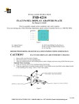
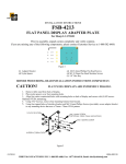
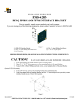
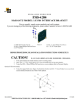
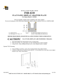
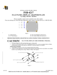
INSTALLATION INSTRUCTIONS
FSB-4202
ZENITH L20V26 INTERFACE BRACKET
Prior to assembly, unpack carton completely and verify contents.
If you are missing any of the following components, please contact Customer Service at 1-800/582-6480
Figure 1
(1) Interface Bracket
(4) M4-.7 x 16mm Phillips Pan Head Screw
(1) 1/8” Hex Key
(4) M4 Flat Washer
(4) ½” X 1/4” Nylon Spacer
(4) M4-.7 x 6mm Phillips Pan Head Screw
BEFORE PROCEEDING, READ INSTALLATION INSTRUCTIONS COMPLETELY
CAUTION!
FLAT PANEL DISPLAYS ARE EXTREMELY FRAGILE.
1. If flat panel display has stand attached, remove existing stand.
2. Place (4) ½” X 1/4” Nylon spacers over four mounting holes in flat panel display.
3. Using (4) M4 x 16mm Phillips pan head screws, secure adapter plate to flat panel display.
Optional VESA Mounting
4. Using 1/8” hex key, remove (4) mounting buttons from adapter bracket.
5. Using four tapped holes (see Figure 2) of interface bracket and M4-.7 X 6mm Phillips Screws (provided),
secure interface bracket to any 75mm VESA pattern.
Figure 2
8804-000036
12/10/03
CHIEF MANUFACTURING INC. 1-800-582-6480, Fax: 1-877-894-6918, Email: [email protected]