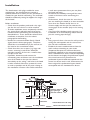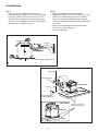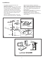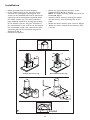
1
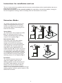
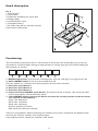
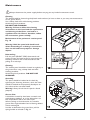
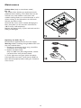
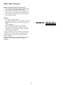
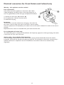
KCDP 9010/I
Instructions for use
Warnings
4
Safeguarding the environment
5
Instructions for installation and use
6
Extraction Modes
6
Installation
7
Hood description
11
Functioning
11
Maintenance
12
After-Sales Service
14
Warnings
• This appliance should not be used by children or people with limited physical or mental
abilities and with no experience or knowledge of its use, unless they are supervised by
someone in charge of their safety or who has taught them how to use the appliance.
• Children should not play with the appliance.
1.
Do not connect the appliance to the mains supply until the installation is completely finished.
Before carrying out any cleaning or maintenance work, always disconnect the hood from the mains
supply by pulling out the plug or turning off the mains switch in the house.
2. Do not flambé food under the hood since the flames generated could cause a fire.
3. Do not leave a frying pan unattended when frying food as the cooking oil could catch fire.
4. Constant cleaning and maintenance of your hood will ensure it works properly. Regularly remove all the
ingrained food from dirty surfaces. Regularly remove and clean or change the filter. Do not use
inflammable material to convey exhaust air.
5. If the hood is used in conjunction with other appliances that run on gas or other fuels, the negative
pressure of the room should be no greater than 4Pa (4 x 10⁻⁵ bar). This is why you should make sure
the room is well aired.
6. Exhaust air from the hood should not be eliminated through the heating system chimney or appliances
that run on gas or other fuels.
7. The room should be sufficiently ventilated when the hood is used together with other appliances that
run on gas or other fuels.
8. Before touching the light bulbs, make sure they have cooled down.
Note: always use gloves when installing or carrying out maintenance work.
Electrical connection
The mains voltage should correspond with the voltage shown on the specifications label found inside the
hood. If there is no plug, connect the hood to a socket that complies with current legislation and is in an
easily accessible location. If there is no plug (direct connection to the mains supply) or the plug is not in an
easily accessible location, fit a legally complying bi-polar switch that ensures the complete disconnection of
the mains in the event of a category III line surge, in compliance with the installation regulations.
IMPORTANT: before reconnecting the hood circuit to the power supply, check that it is
working properly, that the mains cable has been properly fitted and that it has NOT been
crushed in its holder during installation.
Cleaning the hood
Warning! Failure to remove oil/grease (at least once a month) could lead to a fire breaking out. Use a soft
cloth and mild cleaning product. Never use harsh substances or alcohol.
Before using the hood
To get best performance from the hood, please read these user instructions carefully and keep them for
future reference.
Keep the packaging material (plastic bags, pieces of polystyrene, etc.) out of children’s reach as they can be
dangerous.
Make sure the hood has not been damaged during transportation.
The installation and the electrical connections, replacement of power cables with plug or flexible cable
should be carried out by a qualified technician in compliance with current legislation in force.
This appliance was designed to be used by adults.
4
Warnings
Declaration of conformity
This product has been designed, manufactured and marketed according to the following:
- safety objectives of the “Low Voltage” Directive 2006/95/CE (wich replaces 73/23/CEE and subsequent
amendments).
- protection requirements of “EMC” Directive 89/336/EEC amended by Directive 93/68/EEC.
Troubleshooting guide
Hood does not work:
• Is the electrical power supply switched on?
• Is there a power failure?
Insufficient suction power:
• Did you set the right speed?
• Do the filters need to be cleaned or replaced?
• Are the air outlets blocked?
Light does not work:
• Does the bulb need to be replaced?
• Is the bulb correctly fitted?
Safeguarding the environment
1. Packing
The packaging material is entirely recyclable and marked with the recycling symbol
. Follow local
regulations for scrapping. Keep the packaging materials (plastic bags, polystyrene parts, etc.) out of reach
of children, as they are potentially dangerous.
2. Product
This appliance is marked according to the European Directive 2002/96/EC, Waste Electrical and Electronic
Equipment (WEEE).
By ensuring that this product is disposed of correctly, you will help prevent potentially negative
consequences for the environment and human health.
The symbol
on the product or on the documents accompanying the product indicates that this
appliance may not be treated as household waste. Instead, it should be handed over to the applicable
collection point for the recycling of electrical and electronic equipment.
Disposal must be carried out in accordance with local environmental regulations for waste disposal.
For more detailed information on treatment, recovery and recycling of this product, contact your local
authority, the household waste disposal service or the shop where you purchased the product.
5
Instructions for installation and use
This is an excessively heavy product and the movement and installation of the hood should be done by at
least two or more people.
Follow the instructions in this manual carefully. All responsibility is denied for problems, damage or
fire to the appliance resulting in failure to comply with the instructions in this manual.
Extraction Modes
The hood is designed to be used in two
modes: Venting exhaust fumes to the
outside, or by passing the air through a
charcoal filter brfore recirculating the air
back into the kitchen.
Vented Mode
The hood comes with an upper air outlet
B for the discharge of fumes to the
outside (vented exhaust pipe and fixing
straps are not supplied). Fig. 1
Recirculation Mode
If the fumes and steam from cooking
cannot be discharged towards the
outside, you can use the recirculation
mode by fitting an activated carbon filter
(not supplied, this must be purchased
seperately) and the deflector F on the
support (bracket) G; the fumes and steam
are recirculated via the upper grid H and
an exhaust pipe, connected to the upper
air outlet B and the connection ring fitted
to the deflector F (venting exhaust pipe
and fixing straps are not supplied). Fig. 2
Installation
The minimum distance between the
upper pan support surfaces on the
cooking appliance and the lowest part of
the cooker hood should be no less than
50 cm in the case of electrical cookers
and 70 cm in the case of gas or mixed
cookers. If the installation instructions for the gas
cooking appliance specify a greater distance, then
follow that instruction.
6
Installation
The hood comes with plugs suitable for most
walls/ceilings. You should however consult a
qualified technician to make sure the installation is
suitable for your kind of wall/ceiling. The wall/roof
should be sufficiently strong to support the weight
of the hood.
it with some protection where you can place
the hood and parts.
• Disconnect the hood by turning off the mains
switch in the house when connecting the
electrics.
• Furthermore, check that near the area where
you are installing the hood (in an area accessible
even when the hood is fitted) there is an
electric supply and that you can connect the
venting pipe to the outside (only in the venting
mode).
• Carry out all the building work necessary (e.g.:
installation of an electrical plug and/or hole to
pass the venting pipe through).
Before installation:
• Check that the product purchased is the right
size for the area where it is to be installed.
• To make installation easier, temporarily remove
the grease filters and other parts that can be
removed whose dismantling and assembly are
described here. These should be refitted when
installation is complete. See the relative
paragraph for dismantling.
• Remove the activated carbon filter/s if fitted
(again consult relative paragraph). This/these
should be re-assembled only if you wish to use
the hood in the recirculation mode.
• Check that there are no parts (e.g. bags with
screws, warranty) inside of the hood (for
transport reasons). If there are, remove them
and put to the side.
• If possible, disconnect and remove the
surrounding units and those near the installation
area of the hood so that you have better
accessibility to the ceiling / wall where the hood
is to be installed. Otherwise, protect the units
as much as possible and all the parts relating to
the installation. Choose a flat surface and cover
Fig. 3
• Using a pencil, draw a line on the wall up to the
ceiling that corresponds with the centre line;
this will make installation easier.
• Establish the most suitable distance from the
work surfaces according to your needs
(Important! Respect the minimum distances
specifically indicated in this instruction booklet),
draw a horizontal line on the wall corresponding
to this distance and apply the perforation layout:
the vertical centre line printed on the
perforation layout should correspond with the
centre line drawn on the wall; furthermore the
lower edge of the perforation layout should
correspond with the horizontal line drawn.
ceiling
wall
Venting exhaust
pipe passages
and side cabinet
side cabinet
min. width of hood
centre line
Cooking surface
7
* Recirculation mode only
all measurements in mm
Installation
Fig. 4
• Place the lower support bracket on the
perforation layout aligning it with the sketched
rectangle. Mark the two external holes, then
drill the holes. Remove the perforation layout
and insert 2 wall plugs and fix the hood support
bracket with 2 5x45mm screws.
Fig. 5
• Hang the hood on the lower bracket.
• Adjust the distance of the hood from the wall.
• Adjust the horizontal position of the hood.
• From the inside of the hood, make 2 pencil
marks for the holes ready for the final fitting of
the hood.
• Remove the hood from the lower bracket.
• Drill in the points indicated.
• Insert 2 wall plugs.
Centre line
support
bracket
mounting height reference
centre line
support bracket
FRONT VIEW
hooks
bottom fastener
locations Ø 8 mm
REAR VIEW
bottom screw hole
(inside the canopy)
hooks
8
Installation
• The hood has two identical brackets for
attaching the chimney.
Attach the first bracket (G – the side with fixing
holes facing upwards – see Fig. 6) to the wall
next to the ceiling, using the support bracket as
a template (the small slots cut in the bracket
should coincide with the centre lines previously
traced on the wall), mark 2 holes with a pencil,
drill the holes and attach the bracket with 2
screws and plugs.
Attach the second bracket (M – the side with
holes for attaching facing upwards – see Fig. 6)
above the lower bracket at a distance of
200mm, attach the bracket with 2 screws and
plugs. 2 rubber strips should be attached to the
sides of this second bracket (one strip on each
side – cut the rubber strip provided into two
identical halves).
• Recirculation mode Only: fit the deflector to
the chimney support bracket. Fig. 6
• Chimney size: the chimney is supplied in a
standard size and can then be cut to measure as
shown in Fig. 7.
chimney
support
bracket
centre line
Deflector
lower
support bracket
lower
fitting device
bracket
bottom
fastener locations
9
chimney
support bracket
Installation
• Hook the hood onto the lower bracket.
• Fit the hood securely to the wall with screws
• Connect the venting pipe (Venting pipe and
straps are not provided and must be purchased
seperately) to the connection ring found above
the motor suction unit. The other end of the
pipe should be attached to venting pipe leading
to the outside if you are using the extractor in
the vented mode. If you wish to use the hood in
the recirculation mode, then connect the other
end of the pipe to the connection ring on the
deflector F. Fig. 8
• Connect the electrics.
• Attach the upper chimney and fix it to the
support bracket G with 2 screws.
Note: The upper chimney should also cover the
bracket M. Fig. 6
• Install the lower chimney covering the power
unit and insert it into its locating slot on the
hood.
• Attach the lower chimney with 2 screws. Fig. 8.
• Attach the lower suction of the chimneys with
2 screws.
Vented extraction only
Recirculation mode only
10
Hood description
Fig. 9
1. Control panel
2. Grease filter
3. Handle for unhooking the grease filter
4. Halogen bulbs
5. Steam deflector screen
6. Telescopic chimney
7. Air outlet (only for use with filter version)
8. Perimetric suction panel
Functioning
Turn to maximum speed when there is a lot of steam in the kitchen. We would advise you to turn the
extraction on 5 minutes before starting to cook and leave it running after you have finished cooking for
about another 15 minutes.
1. ON/OFF light button: press once for a dimmed light, twice for a full light. Press again to turn off
2. Motor ON/OFF button: Press to turn the hood on or off.
Once the hood is on, it extracts at the speed (power) of the previous selection.
3. Extraction speed button 1
4. Extraction speed button 2
5. Extraction speed button 3
6. Intense extraction ON/OFF speed button: This feature lasts for 5 minutes, after which the hood
returns to previously selected extraction speed.
7. Timer ON/OFF button: pressing this button can limit the running duration of the extraction
rate selected to the following:
Speed 1 for 20 minutes.
Speed 2 for 15 minutes.
Speed 3 for 10 minutes.
Intensive speed for 5 minutes.
After which the hood turns itself off.
If there are any problems, before contacting the Customer Care Centre, disconnect the appliance from
the mains for at least 5 seconds, then reconnect again.
If the problem persists, contact the Customer Care Centre.
11
Maintenance
Always disconnect the power supply before carrying out any kind of maintenance work.
Cleaning
The hood should be cleaned regularly both inside and out (at least as often as you carry out maintenance
on the grease filters).
Use a damp cloth with mild cleaning products.
Avoid using harsh products.
DO NOT USE ALCOHOL!
Warning: Failure to follow the cleaning
instructions on the hood and the replacement
and cleaning of the filters, can lead to a
significant fire risk. Please, therefore, follow
the instructions given carefully.
Maintenance of the perimetric suction panel.
Fig. 10
Warning! Hold the panel with both hands
when dismantling or re-fitting it to ensure it
does not fall and harm people or damage
objects.
Dismantling:
Pull the panel (FRONT SIDE) downwards and
release it from the back hinges by unscrewing the
fastening elements with a flat screwdriver and
pulling on it sideways.
Cleaning:
The suction panel should be cleaned as regularly as
the grease filter, using a damp cloth and mild
cleaning products.
Avoid using harsh products. DO NOT USE
ALCOHOL!
Assembly:
The panel should be hooked on the back by
tightening the fastening elements, while the front
should be locked to the purposely fitted pins on
the surface of the extractor hood.
Warning! Always check that the panel is fitted
properly.
Grease filter
It should be cleaned by hand once a month with
mild cleaning products, or in the dishwasher at a
low temperature and on the short cycle.
When washing in the dishwasher, the metallic
grease filter might discolour but its filtering abilities
remain unchanged.
In order to dismantle the grease filter, pull the
spring handle to unhook it. Fig. 11
12
Maintenance
Carbon filter (only in recirculation mode)
Fig. 12
The Carbon filter absorbs any unpleasant smells
produced when cooking. The carbon filter can be
washed every two months in hot water with
suitable cleaning fluids, or in the dishwasher at 65°C
(when washing in the dishwasher, do a full wash
without any plates inside).
Shake off any excess water without damaging the
filter, then place it in the oven for 10 minutes at
100°C to dry it off completely.
Replace the sponge every 3 years and each time the
cloth gets damaged.
Replacing the bulbs Fig. 13
Disconnect the appliance from the mains supply.
Warning! Before touching the light bulbs make sure
they have cooled down.
1. Remove the protective cover using a small flat
screwdriver or a similar tool.
2. Replace the blown bulb.
Only use 20W max (G4) halogen bulbs, and do
not touch them with your bare hands.
3. Fit the light cover on again (clicks into place).
If the light does not work, check that the bulb has
been inserted properly before calling the Customer
Care Centre.
13
After-Sales Service
Before calling Customer Care Centre:
1. See if you can solve the problem yourself with
the help of the “Troubleshooting guide”.
2. Switch off the hood for a few minutes and restart it to see if the problem has cleared itself.
3. If the malfunction persists, call the Customer
Care Centre Service.
Specify:
• the nature of the problem,
• the product model on the rating plate inside the
hood and visible when you remove the grease
filters,
• your full address,
• your telephone number and area code,
• the service code (number below the word
SERVICE on the rating plate inside the hood
behind the grease filter).
If repair work has to be carried out, contact the
Customer Care Centre (this is a guarantee that
original spare parts will be used and a proper
repair job done).
Failure to comply with these instructions could
compromise the safety and quality of your
appliance.
14
Electrical connection for Great Britain and Ireland only
Warning - this appliance must be earthed
Fuse replacement
If the mains lead of this appliance is fitted with a BS 1363A
13amp fused plug, to change a fuse in this type of plug use an
A.S.T.A. approved fuse to BS 1362 type and proceed as follows:
1. Remove the fuse cover (A) and fuse (B).
2. Fit replacement 13A fuse into fuse cover.
3. Refit both into plug.
Important:
The fuse cover must be refitted when changing a fuse and if the
fuse cover is lost the plug must not be used until a correct replacement is fitted.
Correct replacement are identified by the colour insert or the colour embossed in words on the base of
the plug.
Replacement fuse covers are available from your local electrical store.
For the Republic of Ireland only
The information given in respect of Great Britain will frequently apply, but a third type of plug and socket
is also used, the 2-pin, side earth type.
Socket outlet / plug (valid for both countries)
If the fitted plug is not suitable for your socket outlet, please contact KitchenAid Service for further
instruction. Please do not attempt to change plug yourself. This procedure needs to be carried out by a
qualified technician in compliance with the manufactures instructions and current standard safety
regulations.
15
Printed in Italy
05/07
5019 718 02007
n
GB