1
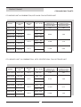
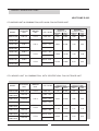
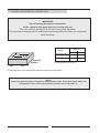
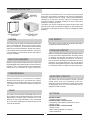
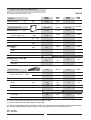
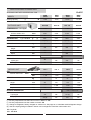
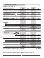
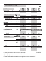
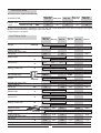
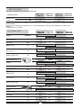
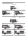
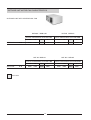
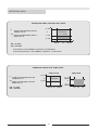
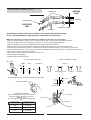
APPLICATION
GUIDE
WING
Congratulations you have made a wise choice with the purchase of your Lennox
air conditioning unit.
This product has been designed, assembled and supplied in one of our world class manufacturing facilities
and we feel sure that it will meet your expectations.
Lennox an international organisation with world wide distribution takes pride in supplying you with this
product.
CONTENTS
CONTENTS
PÁGE
. PRODUCT RANGE
. SYSTEM CONFIGURATION
. GENERAL DESCRIPTION
. SPECIFICATIONS
. ELECTRICAL DATA
. ELECTRICAL CONNECTIONS
. INDOOR MOTOR FAN CHARACTERISTICS
. OPERATING LIMITS
. REFRIGERANT CONNECTIONS
. DIMENSIONS AND SETTING UP TEMPLATES OUTDOOR UNIT
. DESCRIPTION OUTDOOR UNIT
. ENTRANCE STANDARD/ OPTIONAL OUTDOOR UNIT
. DIMENSIONS AND SETTING UP TEMPLATES INDOOR UNIT
. INSTALATION AND MOUNTING
. OPTIONS
MAINTENANCE
. POINTS TO KEEP IN MIND
1
2-3
4
5
6-9
10-11
12-14
15
16
17-19
20
21-22
23
24
25
26-27
28
29
PRODUCT RANGE
COOLING ONLY R-407C
LTX INDOOR UNIT IN COMBINATION, WITH AXIAL FAN OUTDOOR UNIT
MODEL
OUTDOOR
UNIT
INDOOR
UNIT
V / Ph / 50 Hz
NOMINAL
CAPACITY W
COOLING ONLY
NOMINAL
CAPACITY KW
COOLING ONLY
WING 2,8TFK
KJF 2,8K
LTX 3
230V-1Ph
7.350
3,06
WING 3TFK
KJF 3K
WING 3TFK
KJF 3K
9.500
3,85
WING 3TFK
KJF 3K
400 V - 3Ph
WING 4TFK
KJF 4K
230 V - 3Ph
WING 4TFK
KJF 4K
11.600
4,70
WING 5TFK
KJF 5K
WING 5TFK
KJF 5K
13.500
5,60
230V -1Ph
LTX 3
230 V - 3Ph
LTX 5
400 V - 3Ph
230 V - 3Ph
LTX 5
400 V - 3Ph
LTX INDOOR UNIT IN COMBINATION, WITH CENTRIFUGAL FAN OUTDOOR UNIT
MODEL
OUTDOOR
UNIT
INDOOR
UNIT
V / Ph / 50 Hz
NOMINAL
CAPACITY W
COOLING ONLY
NOMINAL
CAPACITY KW
COOLING ONLY
WING 2,8CFK
KCF 2,8K
LTX 3
230V-1Ph
7.130
3,07
WING 3CFK
KCF 3K
WING 3CFK
KCF 3K
9.100
3,86
WING 3CFK
KCF 3K
WING 4CFK
KCF 4K
12.100
5,17
14.000
7,00
WING 4CFK
KCF 4K
WING 5CFK
KCF 5K
WING 5CFK
KCF 5K
230V -1Ph
LTX 3
230 V - 3Ph
400 V - 3Ph
230 V - 3Ph
LTX 5
400 V - 3Ph
230 V - 3Ph
LTX 5
400 V - 3Ph
2
PRODUCT RANGE HEAT PUMP
HEAT PUMP R-22C
LTX INDOOR UNIT IN COMBINATION, WITH AXIAL FAN OUTDOOR UNIT
MODEL
OUTDOOR
UNIT
INDOOR
UNIT
V / Ph / 50 Hz
WING 2,8TB
KJB 2,8
LTX 3
230V-1Ph
WING 3TB
KJB 3
WING 3TB
KJB 3
WING 3TB
KJB 3
WING 4TB
KJB 4
NOMINAL
CAPACITY W
NOMINAL
CAPACITY KW
COOLING
ONLY
HEAT
PUMP
COOLING
ONLY
HEAT
PUMP
7.350
7.800
3,06
2,60
9.250
9.000
3,70
3,00
11.600
12.100
4,70
3,90
13.700
14.600
5,90
5,00
230V -1Ph
LTX 3
230 V - 3Ph
400 V - 3Ph
230 V - 3Ph
LTX 5
WING 4TB
KJB 4
400 V - 3Ph
WING 5TB
KJB 5
230 V - 3Ph
WING 5TB
KJB 5
LTX 5
400 V - 3Ph
LTX INDOOR UNIT IN COMBINATION, WITH CENTRIFUGAL FAN OUTDOOR UNIT
MODEL
OUTDOOR
UNIT
INDOOR
UNIT
V / Ph / 50 Hz
WING 2,8CB
KCB 2,8S
LTX 3
230V-1Ph
WING 3CB
KCB 3S
WING 3CB
KCB 3S
WING 3CB
KCB 3S
WING 4CB
KCB 4S
KCB 4S
WING 5CB
KCB 5S
LTX 3
230 V - 3Ph
KCB 5S
COOLING
ONLY
HEAT
PUMP
COOLING
ONLY
HEAT
PUMP
7.130
8.150
3,07
2,77
9.100
10.220
3,86
3,40
12.100
13.500
5,17
4,33
14.000
17.400
7,00
6,40
400 V - 3Ph
230 V - 3Ph
400 V - 3Ph
230 V - 3Ph
LTX 5
WING 5CB
NOMINAL
CAPACITY KW
230V -1Ph
LTX 5
WING 4CB
NOMINAL
CAPACITY W
400 V - 3Ph
3
SYSTEM CONFIGURATION (INDOOR UNIT)
IMPORTANT
Prior of making the electrical connections,
set the switch for heat pump unit or for cooling only unit.
This unit is valid for operating as a cold only or heat pump application.
The unit should be configured prior to making the electrical connections, by setting the configuration
switch as follows:
SWITCH
MODEL
Switch 2
Switch 1
ON
1
2
COOLING ONLY
(*)
OFF
ON
HEAT PUMP
ON
ON
(*) Configuration from factory..
OFF
Check page 8 for more information about the situation of this switch.
NOTE:
If errors are made during the configuration of the system, switch off the main power supply, set
configuration switch in the correct position and then switch the power on.
4
GENERAL DESCRIPTION
INDOOR
UNIT LTX
OUTDOOR UNIT
KJF/KJB
The ceiling air conditioner SPLIT, on version cooling only and
heat pump, are units air condensed. The indoor unit with direct
air supply, realise function of cooling , heating dehumidification,
cleaning air of the sites. Also the option to incorporate with
maximum facilities a heating resistance on units cooling only
and also on heat pump units.
The indoor unit can be combine with outdoor units provide with
axial fan (KJF/ KJB) for outside installation or with outdoor unit
provide with centrifugal fan (KCF/ KCB) for installation inside
buildings.
OUTDOOR UNIT
KCF/KCB
AIR SWEEP
CABINE
The indoor unit (LTX) have an automatic dispositive
to distribute horizontal air flow.
The outdoor unit is made on electrozinced steel with
epoxy painted finish, able to work outdoors under
the worst conditions. its dimensions and features
allow the unit to be positioned in almost any location.
It incorporate thermal acoustic insulation. The indoor
unit is finished in a decorative plastic with thermal
acoustic insulation.
COOLING CIRCUIT
Made of welded dehydrated copper pipe with service
port on the suction and liquid lines. Coupling valves
on outdoor unit and flare connexion on indoor unit
to facilitate the refrigerant connexion. A muffler in
the compressor discharge line eliminates noise and
pulsation of the discharge line. The unit includes
filter dryer and expansion system. It has unidirectional
and reversing valves of 4 pipes for unit in heat pump.
HEAT EXCHANGER
Made of cooper tubes and aluminium fins. Coils have
been designed and manufactured to ensure maximum
efficiency. The L shaped outside unit heat exchanger
makes this unit compact an highly efficiency.
COMPRESSOR
ELECTRIC CIRCUIT
An hermetically sealed compressor, with internal
thermal protection. It is mounted on vibration
absorbent blocks both on the inside and outside,
statically an dynamically balanced. In all cases the
compressors are acoustically isolated, resulting in
low noise.
The indoor unit electrical panel includes a printed
board, which control the operating of the unit,
defrosting timer thermostat and system of reversing
on heat pump cycle. The unit is controlled from an
infrared remote controller.
FANS
OPTIONS
The indoor units includes centrifugal motor fan of
three speed, with exceptional features on noise level
Depending on outdoor type, it includes one or two
axial motor fan (units KJF/KJB), or one centrifugal
fan (units KCF/ KCB),with exceptional features in
noise level and flow .
OUTDOOR UNIT
• Heating electrical heater.
OUTDOOR UNIT TYPE KJF/KJB
• Supporting with braxkets( depends on units)
• Winter control.
OUTDOOR UNIT TYPE KCF/KCB
• Winter control
• Main switch (depends on models)
• Grille external air
5
SPECIFICATIONS COOLING ONLY
R-407C
OUTDOOR UNIT WITH AXIAL FAN
MODEL
Cooling capacity
(*)
W
OUTDOOR UNIT
COMPRESSOR
Nª / Type
WING
2,8TFK
WING
3TFK
WING
4TFK
WING
5TFK
7.350
9.500
11.600
13.500
KJF 2,8K
KJF 3K
KJF 4K
KJF 5K
1 / ALT.
1 / ALT.
1 / ALT.
1 / ALT.
3.100
5.100
5.400
5.400
1650
2500
2600
2600
Capillary
Capillary
Capillary
FAN
Air flow outdoor unit
REFRIGERANT
m3/h.
Type / R-407C
gr.
EXPANSIÓN
(1)
Capillary
WEIGHT
Kg
78
85
96
98
DIMENSIONS
Height
mm.
781
1035
1035
1035
Width
mm.
973
973
973
973
Depth
mm.
333
333
333
333
mm.
845 x 1060 x 385
PACKING DIMENSIONS
REFRIGERANT COUPLING
Liquid pipe
Gas pipe
Air flow indoor unit
3/8"
3/8"
3/8"
1/2"
5/8"
3/4"
3/4"
3/4"
LTX 3
LTX 3
LTX 5
LTX 5
Max.
1.300
1.300
2.100
2.100
Min.
1.100
1.100
1.800
1.800
INDOOR UNIT
FAN
1085 x 1275 x 385
m3/h.
WEIGHT
Kg
40
40
57
57
DIMENSIONS
Height
mm.
267
267
312
312
Width
mm.
1.409
1.409
1.719
1.719
Depth
mm.
656
656
756
756
PACKING DIMENSIONS
mm.
310 x 1430 x 680
REFRIGERANT COUPLING
Liquid pipe
Gas pipe
352 x 1749 x 776
3/8"
3/8"
1/2" (2)
1/2"
3/4"
3/4" (2)
3/4"
3/4"
(*) Air entry temperature into the indoor unit 27°C DB/19 °C WB
(*) Air entry temperature into the outdoor unit 35ºC DB
(1) Charge of refrigerant, factory charged on outdoor unit. See page 22, to calculate model refrigerant charge.
(2) Use the coupling fittings included in indoor unit for refrigerant connection with outdoor unit.
DB.- Dry Bulb
WB.- Wet Bulb
6
SPECIFICATIONS COOLING ONLY
R-407C
OUTDOOR UNIT WITH CENTRIFUGAL FAN
MODEL
W
(*)
Cooling capacity
OUTDOOR UNIT
COMPRESSOR
Nª / Type
WING
2,8CFK
WING
3CFK
WING
4CFK
WING
5CFK
7.180
9.100
12.100
14.000
KCF 2,8K
KCF 3K
KCF 4K
KCF 5K
1 / ALT.
1 / ALT.
1 / ALT.
1 / ALT.
2.500
2.500
3.400
5.000
40
40
50
50
2255
2350
3070
4950
FAN
Air flow outdoor unit
m3/h.
Available pressure
Pa
REFRIGERANT
Type / R-407C
gr.
(1)
Capillary
EXPANSIÓN
Capillary
Capillary
Capillary
WEIGHT
Kg
89
91
125
140
DIMENSIONS
Height
mm.
505
505
525
575
Width
mm.
1050
1050
1300
1300
Depth
mm.
750
750
855
855
PACKING DIMENSIONS
630 x 1140 x 850
mm.
REFRIGERANT COUPLING
Líquid pipe
775 x 1330 x 865
3/8"
3/8"
3/8"
1/2"
Gas pipe
5/8"
3/4"
3/4"
3/4"
INDOOR UNIT
LTX 3
LTX 3
LTX 5
LTX 5
Max.
1.300
1.300
2.100
2.100
Min.
1.100
1.100
1.800
1.800
40
40
57
57
FAN
Air flow indoor unit
m3/h.
WEIGHT
Kg
DIMENSIONS
Height
mm.
267
267
312
312
Width
mm.
1.409
1.409
1.719
1.719
Depth
mm.
656
656
756
756
PACKING DIMENSIONS
REFRIGERANT COUPLING
Líquid pipe
Gas pipe
mm.
310 x 1430 x 680
352 x 1749 x 776
3/8"
3/8"
1/2" (2)
1/2"
3/4" (2)
3/4"
3/4"
3/4"
(*) Air entry temperature into the indoor unit 27°C DB/19 °C WB
(*) Air entry temperature into the outdoor unit 35ºC DB
(1) Charge of refrigerant, factory charged on outdoor unit. See page 22, to calculate model refrigerant charge.
(2) Use the coupling fittings included in indoor unit for refrigerant connection with outdoor unit.
DB.- Dry Bulb
WB.- Wet Bulb
7
SPECIFICATIONS HEAT PUMP
R-22
OUTDOOR UNIT WITH AXIAL FAN
MODEL
WING
2,8TB
WING
3TB
WING
4TB
WING
5TB
Cooling capacity
(*)
W
7.350
9.250
11.600
13.700
Heating capacity
(**)
W
7.800
9.000
12.100
14.600
KJB 2,8
KJB 3
KJB 4
KJB 5
1 / ALT.
1 / ALT.
1 / ALT.
1 / ALT.
m3/h.
3.100
3.100
5.400
5.600
gr.
1775
2500
2800
3500
Capillary
Capillary
Capillary
Restrictor
OUTDOOR UNIT
COMPRESSOR
Nª / Type
FAN
Air flow outdoor unit
REFRIGERANT
Type / R-22
EXPANSIÓN
WEIGHT
Kg
81
83
99
129
DIMENSIONS
Height
mm.
781
781
1035
1330
Width
mm.
973
973
973
1005
Depth
mm.
333
333
333
386
1085 x 1275
x 385
1495 x 1057
x 430
845 x 1060 x 385
mm.
PACKING DIMENSIONS
REFRIGERANT COUPLING
Líquid pipe
Gas pipe
3/8"
3/8"
3/8"
1/2"
5/8"
3/4"
3/4"
3/4"
LTX 3
LTX 3
LTX 5
LTX 5
Max.
1.300
1.300
2.100
2.100
Min.
1.100
1.100
1.800
1.800
WEIGHT
Kg
40
40
57
57
DIMENSIONS
Height
mm.
267
267
312
312
Width
mm.
1.409
1.409
1.719
1.719
Depth
mm.
656
656
756
756
INDOOR UNIT
FAN
Air flow indoor unit
m3/h.
PACKING DIMENSIONS
mm.
310 x 1430 x 680
REFRIGERANT COUPLING
Líquid pipe
Gas pipe
352 x 1749 x 776
3/8"
3/8"
1/2" (2)
1/2"
3/4" (2)
3/4"
3/4"
3/4"
DB.- Dry Bulb
(*) Air entry temperature into the indoor unit 27°C DB/19 °C WB
WB.- Wet Bulb
(*) Air entry temperature into the outdoor unit 35ºC DB
(**) Air entry temperature into the indoor unit 20°C DB/12 °C WB
(**) Air entry temperature into the outdoor unit 7ºC DB/6ºCWB
(1) Charge of refrigerant, factory charged on outdoor unit. See page 22, to calculate model refrigerant charge
(2) Use the coupling fittings included in indoor unit for refrigerant connection with outdoor unit..
8
SPECIFICATIONS HEAT PUMP
R-22
OUTDOOR UNIT WITH CENTRIFUGAL FAN
MODEL
WING
2,8CB
WING
3CB
WING
4CB
WING
5CB
Cooling capacity
(*)
W
7.180
9.100
12.100
14.000
Heating capacity
(**)
W
8.150
10.220
13.500
17.400
KCB 2,8S
KCB 3S
KCB 4S
KCB 5S
1 / ALT.
1 / ALT.
1 / ALT.
1 / ALT.
2.500
2.500
3.400
5.000
40
40
50
50
OUTDOOR UNIT
COMPRESSOR
Nª / Type
FAN
Air flow outdoor unit
m3/h.
Available pressure
Pa
REFRIGERANT
Type / R-22
gr.
EXPANSIÓN
(1)
2425
Capillary
2525
Capillary
3400
Capillary
5300
Capillary
Kg
92
94
135
150
mm.
505
505
525
575
Width
mm.
1050
1050
1300
1300
Depth
mm.
750
750
855
855
mm.
630 x 1140 x 850
WEIGHT
DIMENSIONS
Height
PACKING DIMENSIONS
REFRIGERANT COUPLING
Líquid pipe
775 x 1330 x 865
3/8"
3/8"
3/8"
1/2"
Gas pipe
5/8"
3/4"
3/4"
3/4"
INDOOR UNIT
LTX 3
LTX 3
LTX 5
LTX 5
Max.
1.300
1.300
2.100
2.100
Min.
1.100
1.100
1.800
1.800
Kg
40
40
57
57
mm.
267
267
312
312
Width
mm.
1.409
1.409
1.719
1.719
Depth
mm.
656
656
756
756
FAN
Air flow indoor unit
m3/h.
WEIGHT
DIMENSIONS
Height
PACKING DIMENSIONS
REFRIGERANT COUPLING
Líquid pipe
Gas pipe
mm.
310 x 1430 x 680
3/8"
3/4" (2)
3/8"
3/4"
352 x 1749 x 776
1/2" (2)
3/4"
1/2"
3/4"
DB.- Dry Bulb
(*) Air entry temperature into the indoor unit 27°C DB/19 °C WB
WB.- Wet Bulb
(*) Air entry temperature into the outdoor unit 35ºC DB
(**) Air entry temperature into the indoor unit 20°C DB/12 °C WB
(**) Air entry temperature into the outdoor unit 7ºC DB/6ºCWB
(1) Charge of refrigerant, factory charged on outdoor unit. See page 22, to calculate model refrigerant charge
(2) Use the coupling fittings included in indoor unit for refrigerant connection with outdoor unit..
9
SPECIFICATIONS
SET WITH AXIAL FAN OUTDOOR UNIT
SOUND LEVEL
Sound
pressure (Lp)
level
Indoor unit (1)
dBA
Outdoor unit (2)
dBA
WING 2,8TFK
WING 2TB
WING 3TFK
WING 3TB
41/46 (*)
41/46 (*)
41/46 (*)
43/48 (*)
43/48 (*)
55
53
56
56
52
WING 4TFK
WING 4TB
WING 5TFK
WING 5TB
(1) Sound level measured to a distance of 2m from the unit, normal absorption, room size according to unit capacity.
(2) Sound level measured to a distance of 5 m, free space.
(*) High speed / Low speed
ELECTRICAL DATA
WING 2,8TFK
WING 3TFK
WING 2TB
Voltage
WING 4TFK
WING 4TB
WING 3TB
WING 5TFK
WING 5TB
230V / 1 Ph
V/f (50 Hz)
230V-400V / 3 Ph
Nominal total input power
cooling capacity
Nominal total input power
heat pump
Kw
3,06
3,85
3,70
4,70
5,60
5,90
Kw
2,60
----
3,00
3,90
---
5,00
14,87
19,3
18,3
13,4/8,0
12,8/7,7
18,3/9,1
20,4/10,2
21,5/11,3
21,3/12,1
23,1/11,9
24,4/13,2
Rated current
A
Current max.
Starting current max.
A
17,3/10,7
91
KJF 2,8K
KJB 2,8
OUTDOOR UNIT
Voltage
24,4
17,9
A
23,4
16,5/10,2
90
90
78 / 39
78 / 39
106 / 53
124 / 62
124 / 62
KJF 3K
KJB 3
KJF 4K
KJB 4
KJF 5K
KJB 5
230V / 1 Ph
V/f (50 Hz)
230V-400V / 3 Ph
Nominal total input power
cooling capacity
Nominal total input power
heat pump
Rated current
Current max.
Starting current max.
Kw
2,88
3,67
3,52
4,45
5,35
5,65
Kw
2,42
---
2,82
3,65
----
4,75
17,2/8,0
19,2/9,0
20,4/10,2
20,2/11,0
22,1/10,9
23,3/12,1
124 / 62
124 / 62
A
A
A
INDOOR UNIT
Voltage
Nominal total input power
cooling capacity
Nominal total input power
heat pump
Rated current
Starting current max.
14,05
18,48
17,48
13,2/7,1
12,0/6,9
23,58
22,60
16,4/9,8
15,7/9,4
17,12
91
LTX 3
90
90
78 / 39
78 / 39
106 / 53
LTX 3
LTX 3
LTX 5
LTX 5
LTX 5
230V / 1 Ph
V/f (50 Hz)
Kw
0,18
0,18
0,18
0,25
0,25
0,25
Kw
0,18
---
0,18
0,25
---
0,25
A
0,82
0,82
0,82
1,14
1,14
1,14
A
2,46
2,46
2,46
3,42
3,42
3,42
10
SPECIFICATIONS
SET WITH CENTRIFUGAL FAN OUTDOOR UNIT
WING 2,8CFK
WING 2CB
SOUND LEVEL
Sound
pressure (Lp)
level
WING 3CFK
WING 3CB
WING 4CFK
WING 4CB
WING 5CFK
WING 5CB
Indoor unit (1)
dBA
41/46 (*)
41/46 (*)
43/48 (*)
43/48 (*)
Outdoor unit (2)
dBA
57
58
60
62
(1) Sound level measured to a distance of 2m from the unit, normal absorption, duct size and installation according
to unit capacity.
(2) Sound level measured to a distance of 5 m, normal absorption, duct size and installation according to unit
capacity.
(*) High speed / Low speed
ELECTRICAL DATA
Voltage
WING 2,8CFK
WING 2CB
WING 3CFK
WING 3CB
WING 4CFK
WING 4CB
WING 5CFK
WING 5CB
230V / 1 Ph
V/f (50 Hz)
230V-400V / 3 Ph
Nominal total input power
cooling capacity
Nominal total input power
heat pump
Rated current
Kw
3,07
3,86
5,17
7,00
Kw
2,77
3,40
4,33
6,40
16,6/10,0
22,3/13,3
21,9/12,7
24,5/16,7
106 / 53
124 / 62
KCF 4K
KCB 4S
KCF 5K
KCB 5S
A
14,92
18,3
11,7/5,4
Current max.
Starting current max.
19,82
23,4
A
A
16,5/10,2
91
90
78 / 39
KCF 2,8K
KCB 2,8S
OUTDOOR UNIT
Voltage
Nominal total input power
cooling capacity
Nominal total input power
heat pump
Rated current
230V / 1 Ph
V/f (50 Hz)
2,89
3,68
4,92
6,75
Kw
2,59
3,22
4,08
6,15
14,10
17,77
15,5/8,9
21,2/12,2
20,8/11,60
23,4/15,56
78 / 39
106 / 53
124 / 62
LTX 3
LTX 5
LTX 5
A
10,8/4,5
19,00
A
Starting current max.
A
INDOOR UNIT
Starting current max.
230V-400V / 3 Ph
Kw
Current max.
Voltage
Nominal total input power
cooling capacity
Nominal total input power
heat pump
Rated current
KCF 3K
KCB 3S
22,65
15,7/9,4
91
LTX 3
V/f (50 Hz)
90
230V / 1 Ph
Kw
0,18
0,18
0,25
0,25
Kw
0,18
0,18
0,25
0,25
A
0,82
0,82
1,14
1,14
A
2,46
2,46
3,42
3,42
11
ELECTRICAL CONNECTIONS
MODELS 2,8-3-4-5
1
OUTDOOR
UNIT
2
3
ELECTRIC
WIRING DIAGRAM
For electrical connection refer to wiring diagram
in the unit
1
Power supply
2
Connection indoor unit with outdoor unit
3
Sensor connection
1º Remove the front details at the corners and unit cover
panel.
2º Remove the filters
See picture
NUMBER OF WIRES X SECTION
MODEL
VOLTAGE
COOLING ONLY
4
5
2
230 V / 1Ph
3x4mm2
4x1,5mm2
3x4mm2
6x1,5mm
400 V / 3Ph
5x2,5mm 2
4x1,5mm 2
5x2,5mm2
6x1,5mm
230 V / 1Ph
3x4mm2
4x1,5mm2
3x4mm2
6x1,5mm
230 V / 3Ph
4x4mm2
4x1,5mm2
4x4mm2
6x1,5mm
400 V / 3Ph
5x2,5mm 2
4x1,5mm2
5x2,5mm2
6x1,5mm
230 V / 3Ph
4x4mm2
4x1,5mm2
4x4mm2
6x1,5mm
400 V / 3Ph
5x2,5mm2
4x1,5mm2
5x2,5mm2
6x1,5mm
230 V / 3Ph
4x6mm2
4x1,5mm2
4x6mm 2
6x1,5mm
400 V / 3Ph
5x4mm
4x1,5mm2
5x4mm 2
6x1,5mm
2
1
3
1
2.8
3
HEAT PUMP
2
2
2
2
2
2
2
2
2
2
2
2x1,5mm
2
2x1,5mm
2
2x1,5mm
2
2x1,5mm
2
2x1,5mm
2
2x1,5mm
2
2x1,5mm
2
2x1,5mm
NOTE: The sections has been calculated to a distance no superior o 50m and a low supply of 10V
12
2
2x1,5mm
ELECTRICAL CONNECTIONS AND SYSTEM CONFIGURATION
IMPORTANT
Prior of making the electrical connections, set the switch for heat pump unit or for cooling only
unit.
This unit is valid for operating as a cold only or heat pump application. The unit should be configured
prior to making the electrical connections, by setting the configuration switch as follows:
1
3
Remove the front details at the corners and unit cover panel.
Rolling side
DETALLE A
2
Remove the filters
(1)
Filters
Sides and carcass
P.C.B
PCB
NOTE: THE UNIT LEAVES FACTORY
CONFIGURATED ON COOLING MODE
MODEL
SWICHT CONFIGURATION
SWICHT
CONFIGURATION
1
2
COOLING ONLY
(*)
OFF
ON
HEAT PUMP
ON
ON
SWICHT CONFIGURATION
Switch 2
Switch 1
ON
(*) Configuration from factory.
OFF
NOTE:
If errors are made during the configuration of the system, switch off the main power supply, set configuration switch
in the correct position and then switch the power on.
CONNECTIONS OF OUTDOOR UNITS
-FOR HEAT PUMP UNITS, remove the resistor form the terminal
plate and connect the sensor outdoor unit
-FOR COOLING ONLY UNITS, keep connected the resistor.
DON´T TOUCH.
DETAIL B
DETAIL B
5
4
COOLING ONLY
5
4
SENSOR OUTDOOR
UNIT
HEAT PUMP
13
Regleta de terminales, y
conexión de la sonda exterior
ELECTRICAL CONNECTIONS
COOLING ONLY
PE L
N
1
2 3
PE L N
1
2
LTX 3
3
4
OUTDOOR
UNIT
5
230V/50HZ 1Ph + N
PE L
N
1
2 3
PE L1 L2 L3 L3 N
LTX 3-5
N
1
2
PE L
5
4
3
N
1
PE L1 L2 L3 L3 N
OUTDOOR
UNIT
LTX 3-5
2 3
N
1
2
OUTDOOR
UNIT
5
4
3
230V/50HZ 3Ph
400V/50HZ 3Ph + N
Wire overwhelm
HEAT PUMP
CONTROL
SENSOR
4 5
PE L
N
1
2 3
4 5
PE L
N
N
1
2
LTX 3
3
OUTDOOR
UNIT
230V/50HZ 1Ph + N
CONTROL
SENSOR
CONTROL
SENSOR
4 5
PE L
4 5
PE L1 L2 L3 N
N
1
2 3
N
1
3
2
LTX 3
4 5
PE L
OUTDOOR
UNIT
4 5
PE L1 L2 L3 N
N
1
LTX 3
2 3
N
1
3
2
OUTDOOR
UNIT
400V/50HZ 3Ph + N
230V/50HZ 3Ph
CONTROL
SENSOR
CONTROL
SENSOR
4 5
PE L
N
1
2 3
4 5
PE L1 L2 L3 N PE L
N
1
2
3
LTX 5
OUTDOOR
UNIT
230V/50HZ 3Ph
4 5
PE L
N
1
2 3
LTX 5
4 5
PE L1 L2 L3 N PE L
N
1
2
OUTDOOR
UNIT
400V/50HZ 3Ph + N
14
3
OUTDOOR UNIT MOTOR-FAN CHARACTERISTICS
OUTDOOR UNIT WITH CENTRIFUGAL FAN
AIR FLOW
AIR FLOW
m 3/h
m 3/h
KCF2,8K / KCB 2,8S
KCF 3K / KCB 3S
STATIC PRESSUERE AVIALABLE Pa.
STATIC PRESSUERE AVIALABLE Pa.
110
75
40
0
100
70
54
0
1500
1700
2500
2900
1500
1650
2500
2900
KCF 4K / KCB 4S
KCF 5K / KCB 5S
STATIC PRESSUERE AVIALABLE Pa.
STATIC PRESSUERE AVIALABLE Pa.
110
80
50
0
150
110
50
0
2800
3100
3400
3800
4250
4650
5050
5400
AIR FLOW
15
OPERATING LIMITS
OPERATING LIMITS COOLING ONLY UNITS
46° DB
*
Supply air temperature into the
outdoor unit ºC
**
Supply air temperature into the
indoor unit ºC
STANDARD
*
L.A.C. ON/OFF
L.A.C. PROPROC
19° DB
-10° DB
21°/15º
DB/WB
DB.- Dry Bulb
WB.- Wet Bulb
**
32°/23º
DB/WB
THE ON/OFF LOW AMBIENT CONTROL IS STANDARD
THE PROPORTIONAL LOW AMBIENT CONTROL IS OPTIONAL
OPERATING LIMITS HEAT PUMP UNITS
COOL CYCLE
*
Supply air temperature into the
outdoor unit ºC
**
Supply air temperature into the
indoor unit ºC
DB.- Dry Bulb
WB.- Wet Bulb
HEAT CICLE
46° DB
STANDARD
*
19° DB
24°/18º
DB/WB
*
21°/15º
DB/WB
16
**
32°/23º
DB/WB
-8°/-9º
DB/WB
15°
DB
**
27°
DB
REFRIGERANT CONNECTIONS
Flared nuts
INDOOR
UNIT
Coupling
Service valve
OUTDOOR
UNIT
Protective hoods
Insulation
REFRIGERANT CONECTION FOR UNITS WITH COUPLINGS AND SERVICE VALVES
NOTE: THE REFRIGERANT LINES GAS AND LIQUID, MUST BE INSULATED
Make the refrigerant connections between the outdoor and indoor unit, as follows:
-With the valves closed on outdoor unit, unscrew the flare nuts, removing all the protective hoods.
-Unscrew the flare nuts and the coupling on indoor unit, removing the protecting hoods.
-Introduce the flare nuts in the corresponding union tubes, previously isolated.
-Make the thread union of the tubes in valves and coupling using the keys, as shown in the picture.
-To do vacuum, first close the valves on outdoor unit, second connect the plug of the vacuum pump to the
suction valves service port 1/4”, do vacuum to get an absolute pressure of 0.5 mm Hg. This way the vacuum will
be created in indoor unit and union pipes.
-Remove the plugs and open the valves of outdoor unit.
-Verify leakage in couplings.
-Insulate pipes and service ports.
CUT THE PIPE PROPERLY
MAKE A CORRECT FLARE
Pipe cutter
YES
Unpolished
Bent
FAULTY
90°
NO
Bent
Damaged surface
AVOID FROM METALIC DUST ENTERING INTO THE PIPE
Flawed
0-0.5 m.m.
CLEAN THE BURRS
Copper pipe
TIGHTENING TORQUE
Apply the tightening torque shown in the table.
Insufficient tightening torque could cause
refrigerant leak,
excessive tightening torque will damage pipe
flare.
PIPE DIAMETER
TIGHTENING TORQUE
3/8''
31-35 Nm
1/2''
50-55 Nm
3/4''
65-70 Nm
Gas line
Service port
Liquid line
Wrench
17
Irregular
REFRIGERANT CONNECTIONS
DISTANCES BETWEEN UNITS
To locate the outdoor and the indoor units, refer to the
following information.
L : Distance length between both units.
1 = Refrigerant vapour line.
2 = Liquid aspiration line.
INDOOR U.
OUTDOOR U.
2
L
OUTDOOR U.
2
1
1
L
INDOOR UNIT
OUTDOOR U.
1
INDOOR U.
2
L
2,8
3
4
Liquid
3/8"
3/8"
3/8"(1)
1/2"
Vapour
5/8"(1)
3/4"
3/4"
3/4"
Máx.Vertical
Total vertical
+
Horizontal
15
15
15
15
20
25
20
20
8
12
8
8
MODEL
Tube size
Refrigerant lines sizes
Refrigerant lines sizes L
Max. number of bends
5
If the height length is greater than 5 meters, a siphon suction must be installed on the suction line every 5 meters
to ensure that oil return to the compressor.
(1) Use the coupling fittings included in indoor unit for refrigerant connection with outdoor unit..
NOTE: THE REFRIGERANT LINES GAS AND LIQUID, MUST BE INSULATED
For other positions and longer lengths, consult the Lennox Technical Support Department for application
assistance.
The following data will be obtained from that estimation:
Pipe dimensions, Siphon suction, Insulation, Refrigerant charge
18
REFRIGERANT CONNECTIONS
REFRIGERANT CHARGE
OUTDOOR UNITS TYPE KJF-K/ KJB
2,8
3
4
5
(gr.) (*)
(gr.) (**)
1.650
2.500
2.600
2.600
5
5
5
5
(gr.) (***)
30
30
30
55
(gr.) (*)
1.775
2.500
2.800
3.500
(gr.) (**)
5
5
5
5
(gr.) (***)
45
45
45
105
MODEL
COOLING
ONLY
HEAT
PUMP
OUTDOOR UNITS TIPO KCF-K/ KCB
2,8
3
4
5
(gr.) (*)
(gr.) (**)
2.255
2.350
3.070
4.950
5
0
5
5
(gr.) (***)
30
30
30
55
(gr.) (*)
2.425
2.525
3.400
5.300
(gr.) (**)
5
0/5
5
5/0
(gr.) (***)
45
45
45
105
MODEL
COOLING
ONLY
HEAT
PUMP
(*) Refrigerant charge R-22 precharge from factory on the outdoor unit.
(**) Meter of installation line where outdoor unit is precharged+charge also to the group
(***) If line is different to meters indicated on table put more or less charge of refrigerant per meter indicated.
EXAMPLE:
If you need to install a group WING 5CFK, with distance of line between indoor and outdoor unit of 6 meter. The
refrigerant charge R-407C needed in the installation is:
Charge precharge on outdoor unit
= 5300
55
Charge per line 55gr/m x (6-5)m
=
Total charge of the installation = 5355 gr
19
DIMENSIONS OF OUTDOOR UNIT WITH CENTRIFUGAL FAN (mm.)
MODELS
KCF-K / KCB-S 2,8-3
MAXIMUM DIMENSIONS
A
A
C
B
B
C
MODELS
KCF-K / KCB-S- 4-5
A
C
B
AIR OUT
STANDARD
SETTING UP
TEMPLATE (mm)
UNITS 2-2,5-2,8-3
KCF-K
KCB-S
2,8-3
4
5
A
490
525
575
B
1050
1300
1300
C
750
830
830
A
505
525
575
B
1100
1300
1300
C
841
890
890
AIR IN
STANDARD
A
AIR IN
OPTIONAL
B
B
AIR OUT
OPTIONAL
Use 4 rod of a diameter of 10mm if the unit is fixed in
the roof , or screw M.10 if the unit is fixed on the ground.
A
B
1064
660
Dimensions recommended on
point A and B are refered to the
hole of support of the unit.
A
KCF / KCB-S- 2,8 - 3
20
B
DESCRIPTION OUTDOOR UNIT KCF-K / KCB 2,8-3
14
15
13
1
14
AIR IN
STANDARD
15
2
10
33
6
4
5
7
8
12
1
FAN
10 DRAINGE ( O 16 EXTERNAL)
2
EXCHANGER
11 REARM ON ON HIGH PRESSOSTAT
3
COMPRESSOR
12 INTAKE PRESSURE (MOD.2,8-3)
4
CONNETION PIPE
13 CONDENSATE PUMP
5
ACCESS PANEL TO COMPRESSOR AND PIPES COMPONENTS
14 AIR OUT
6
ELECTRICAL BOX
POSICIÓN STANDARD
7
ACCESS PANEL TO ELECTRICAL BOX
POSICIÓN OPCIONAL
8
MAIN SWITCH (OPTIONAL)
9
ELECTRICAL SUPPLY ENTRY ELECTRICAL SUPPLY
15 AIR IN
POSITION STANDARD
POSTION OPTIONAL
11
6
4
12
8
3
9
10
ACCESS TO ELECTRICAL BOX
In the electrical box is included the mechanism of high
pressostat rearm.
21
DESCRIPTION OUTDOOR UNIT KCF / KCB-S 4 - 5
1
8
9
2
6
4
3
7
3
5
6
1
FAN
2
EXCHANGER
3
COMPRESSOR
8
11
12
AIR OUT
POSICIÓN STANDARD
POSICIÓN OPCIONAL
4
ELECTRICAL BOX
5
CONNETION PIPE
6
ACCESS PANEL TO COMPRESSOR AND PIPES COMPONENTS
7
9
10
8
9
AIR IN
POSITION STANDARD
POSTION OPTIONAL
ACCESS PANEL TO ELECTRICAL BOX
10 DRAINGE ( O 16 EXTERNAL)
11 ELECTRICAL SUPPLY ENTRY ELECTRICAL SUPPLY
12 MAIN SWITCH (OPTIONAL)
5
8
9
6
12
10
11
22
ENTRANCE STANDARD/ OPTIONAL OUTDOOR UNIT KCF-K / KCB
ENTRANCE STANDARD
MODELS 2,8-3
E
E
E
RETURN AIR
OPTIONAL
SUPPLY AIR
D
F
F
RETURN AIR
A
G
B
H
K
25
C
RETURN AIR
STANDARD
E
E
ENTRANCE OPTIONAL (TO BE REALISE BY THE INSTALLATOR
F
D
A
B
J
K
F
D
SUPPLY AIR
OPTIONAL
SUPPLY AIR
RETURN AIR
M
SUPPLY AIR
STANDARD
L
L
RETURN AIR
OPTIONAL
MODELS 4-5
E
K
ENTRANCE STANDARD
F
D
N
SUPPLY AIR
RETURN AIR
A
G
B
RETURN AIR
STANDARD
H
C
M
A
B
N
SUPPLY AIR
J
K
F
RETURN AIR
D
D
E
ENTRANCE OPTIONAL (TO BE REALISE BY THE INSTALLATOR)
SUPPLY AIR
OPTIONAL
SUPPLY AIR
STANDARD
L
L
To change entrances from standard position to optional position, you must sustitute the entrance panel correspondent,
and refixe using the same fixation screw.
A
B
C
D
E
F
G
H
J
K
KCF-K / KCB 3S
350
470
1050
490
36,5
400
45.5
35,5
147
53,5
750 332,5
KCF-K / KCB 4S
500
375
1300
525
36
432
195
110
65
35,3
830
50
293,4
KCF-K / KCB 5S
500
375
1300
575
36
432
195
110
65
35,3
830
50
293,4
23
L
M
N
---
DIMENSIONS AND SETTIING UP TEMPLATES OF OUTDOOR UNIT WITH AXIAL FAN
FLOOR MOUNTED
Mi n
. 15
0 (*
*)
KJF-K
KJB
Ø 12
KJF-K
KJB
E
F
Min. 300 (**)
G
Min. 300 (**)
D
E
F
B
OUTDOOR UNIT
KJF-2.8K KJF-3K
C
KJB-2.8
A
(**)
A
B
C
D
E
F
G
ALWAYS KEEP
FREE
KJF-4K
KJB-3
KJB-4
973
781
333
620
176,4
973
1.035
973
781
973
1.035
333
620
176,4
333
620
176,4
333
620
176,4
10
343,5
10
343,5
10
343,5
10
343,5
KJF-5K
KJB-5
973
1.035
333
620
176,4
10
343,5
1.005
1.330
386
602
198
10
410
DIMENSIONS AND SETTING TEMPLATES OF INDOOR UNIT LTX
00 (
**)
FLOOR MOUNTED
J
J
K
H
B
Min
.1
I
C
A
D
223
656
1.104
268
G
H
I
J
K
14
359,5
267,5
177,5
52
460
L
M
653
162,5
N
131
261,5
383
312,5
F
177,5
78
508
753
213
157
D
E
F
N
F
1.076
LTX 5
LTX 3
M
D
E
756
1.330
807
L
B
C
L
1.719
F
N
1.409
E
M
A
F
G
LTX 5
G
LTX 3
24
INSTALLATION INDOOR UNIT
INSTALLATION UNIT
Install the unit in a way that the discharge air would not be direct to persons, differences of temperature can create
disturbs.
Keep in mind in the installation of the unit, some ambient can supply electromagnetic radiation that can affect the
good function of the unit, follow then the following instruction recommended in this document.
Rolling sides
A
A
To remove the casing, slide them over the rolling
sides and remove horizontally (See picture A).
Sides and carcass
B
Filters
B
Remove the AIR VANES by moving them in the
opposite direction of the air sweep motor until
they come out, then release the central fixing
clip, so that the AIR SWEEP is removed giving
better access to the top of the unit (See picture
B).
AIR-SWEEP
C
C
Install the unit with the M-8 screws, always use
washers. Fix the screws following the pattern
on page 26.
Check the strength of the screws to avoid
movement of the indoor unit when removing the
side and cover panel.. See picture C
Min. 100 mm.
D
D
Always install the filters. If the unit operates
without filters there is a risk of damage in the
indoor unit from dust..
OPENING IN FLASE CEILING
X
LTX 3
LTX 5
1.321 mm
1.630 mm
X
Y
562 mm
670 mm
25
Y
INDOOR UNIT OPTIONALS
ELECTRICAL HEATER
BEFORE ATTEMPTING TO PERFORM ANY SERVICE OR MAINTENANCE, TURN OFF
THE ELECTRICAL POWER, AND CHECK THAT THE FAN HAS STOPPED
1
2
3
4
5
To remove the casing, slide them over the rolling sides and remove horizontally
Remove the filters.
Remove drain pan.
Introduce the electrical heater kit rods in the holes of one side of the coil and fix with screws on the other.
Fix the contactor to the fan deck.
Rolling side
Sides and carcass
Filters
Contactor
Drain pan
Electric heat
FIG 1
Contactor
Fan
LTX 3
Electric Heat
Contactor
Fan
LTX 5
Electric Heat
NOTE: The safety thermostat must always be at the top of the heater.
26
OUTDOOR UNIT OPTIONALS
MAIN SWITCH
The main swicth is located on the access panel to the electrical box, in such a way that the unit is disconnected
when the panel is opened, for the models KCF and KCB.
(Refer to the size diagram on pages 25 to 30, to see the position of the electrical box access panel)
WINTER CONTROL
The low ambient kit should be fitted to the cooling units, when the outdoor temperature is lower then 19 ºC. in
cooling cycle.Keeps condensing temperature constant aprosimatelly 40ºC.
KIT GRID OF TAKES OF FOREIGN AIR
Field assembly.
This kit is comprised of an air filter and grille for outdoor air intake which should be installed on the suction side
of the outdoor unit.
27
MAINTENANCE OF THE UNIT
POSSIBLE PROBLEMS
PROBLEM
1.- Unit do not work.
2.- The fan of the unit
works quicker without any
SOLUTION
• Check electrical supply of the unit.
• Check electrical connexion.
• Check the remote controller and parameter works correctly.
• Check that the filter of the unit is clean.
• Check electrical connexion.
• If the problem persist, check the function of the motor.
3.- Noise on pipe system.
NOTE: Some noises are
• Check refrigerant charge is correct.
normal when unit stop and • Was the vacuum done correctly?
• Check internal temperature, could be quite low.
• Check possible obstructions in the condensate pan, and also out of the pan.
4.- Excess of condensation • Check correct level of the unit.
• Check drainage pipe.
5.- The indoor battery
freeze continuously.
• Check the air filter of the indoor unit.
• Check the level of refrigerant.
• Check strangulation air flow or recirculation.
• If the freeze persist the expansion can be obstructed.
• ¿Is the temperature below 21 º C?
• Check indoor temperature sensor.
6.- Unit work perfectly on • Check if you have configurate correctly the function mode of the unit.
cooling mode, but do not • Check inverter valve of the outdoor unit.
produce heat on mode heat • Check the plate PCB to the solenoid inverted valve.
7.-External fan stop
8.-Excessive pressure of
condensation (Working
cooling cycle)
9.-Low pressure
condensation.
(Working on cooling
cycle)
• Check that terminal connexion are slack.
• Check the motor.
• Check the condenser situation.
• Check that that the rele of defrost is not activited
(Units heat pump).
• Check that the external exchanger is not dirty and obstructed.
• Check that there is no condensable gas and air in the refrigerant circuit.
• Check that the external fan works correctly.
• Check that the refrigerant charge is correct
• Check that the refrigerant charge is correct
• Check possible obstruction on the expansion system of the outdoor unit, liquid
• Check that air filter is not dirty or wrong function of indoor fan.
10.-Excessive pressure
on return air (Working
on heat pump)
• Check that the refrigerant charge is correct
• Check the situation of inverter valve.
• Check retention valve situation.
11.-Low pressure on
return air. (working
on heat pump)
•
•
•
•
Check that the refrigerant charge is correct
Check possible obstruction on the expansion system of the outdoor unit
Check that the external fan works correctly.
Check the correct function of the defrost thermostat .
28
POINTS TO KEEP IN MIND
Abrasive
surfaces
Low
temperatures
High
temperatures
Risk of injury with
moving objects
WARNING
Electric shock hazard can cause injury
or death. Before attempting to perform
any service or maintenance on the
unit, turn OFF the electrical power,
and check that the fan has stopped.
Electrical
voltage
Risk of injury with
rotating objects
The air filter cleaning operations do not
require technical service; however when
an electrical or mechanical operation
is required call an Engineer.
FILTER CLEANING
Check the air filter and make
sure it is not blocked with dust
or dirt.
If the filter is dirty, wash it in a bowl with neutral
soap and water, drying it in the shade before
inserting it in the unit.
Standard Guidelines to Lennox Refac equipment
All technical data contained in these operating instructions including the diagrams and technical description
remains the property of Lennox Refac and may not be used (except for the purpose of familiarising the user
with the equipment), reproduced, photocopied, transferred or transmitted to third parties without prior written
authorisation from Lennox Refac.
The data published in the operating instructions is based on the latest information available. We reserve the
right to make modifications without notice.
We reserve the right to modify our products without notice without obligation to modify previously supplied
goods.
These operating instructions contain useful and important information for the smooth operation and maintenance
of your equipment.
The instructions also include guidelines on how to avoid accidents and serious damage before commissioning
the equipment and during its operation and how to ensure smooth and fault-free operation. Read the operating
instructions carefully before starting the equipment, familiarise yourself with the equipment and handling of
the installation and carefully follow the instructions. It is very important to be properly trained in handling the
equipment. These operating instructions must be kept in a safe place near the equipment.
Like most equipment, the unit requires regular maintenance. This section concerns the maintenance personnel
and management.
If you have any queries or would like to receive further information on any aspect relating to your equipment,
do not hesitate to contact us.
29
30
BELGIUM :
CZECH REPUBLIC :
FRANCE :
GERMANY :
LENNOX BENELUX N.V./S.A.
tél. : + 32 3 633 30 45
fax : + 32 3 633 00 89
e-mail : [email protected]
LENNOX JANKA
tél. : + 420 2 510 88 111
fax : + 420 2 579 10 393
e-mail : [email protected]
LENNOX FRANCE
tél. : + 33 4 72 23 20 20
fax : + 33 4 78 20 07 76
e-mail : [email protected]
LENNOX DEUTSCHLAND GmbH
tél. : + 49 69 42 09 79 0
fax : + 49 69 42 09 79 40
e-mail : [email protected]
MIDDLE EAST :
LENNOX DISTRIBUTION
tél. : + 971 4 262 9309
fax : + 971 4 266 7082
e-fax : + 1 240 368 73 62
Mobile : 971 50 4510669
e-mail : [email protected]
NETHERLANDS :
LENNOX BENELUX B.V.
tél. : + 31 33 2471 800
fax : + 31 33 2459 220
e-mail : [email protected]
POLAND :
PORTUGAL :
RUSSIA :
SLOVAKIA :
SPAIN :
UKRAINE :
LENNOX POLSKA Sp. z o. o.
tél. : + 48 22 832 26 61
fax : + 48 22 832 26 62
e-mail : [email protected]
LENNOX CLIMATIZAÇAO LDA.
tél. : +351 22 999 84 60
fax : +351 22 999 84 68
e-mail : [email protected]
LENNOX DISTRIBUTION MOSCOW
tél. : + 7 095 246 07 46
fax : + 7 502 933 29 55
e-mail : [email protected]
LENNOX SLOVAKIA
tél. : + 421 2 44 87 19 27
fax : + 421 2 44 88 64 72
LENNOX REFAC S.A.
tél. : + 34 915 40 18 10
fax : + 34 915 42 84 04
e-mail : [email protected]
LENNOX DISTRIBUTION KIEV
tél. : + 380 44 213 14 21
fax : + 380 44 213 14 21
e-mail : [email protected]
UNITED KINGDOM :
LENNOX INDUSTRIES LTD
tél. : + 44 1604 599400
fax : + 44 1604 594200
e-mail : [email protected]
OTHER EUROPEAN
COUNTRIES, AFRICA,
LENNOX DISTRIBUTION :
tél. : + 33 4 72 23 20 14
fax : + 33 4 72 23 20 28
e-mail : [email protected]
MIL55S-101
05-2001
w w w. L e n n oxe u ro p e . c o m