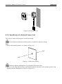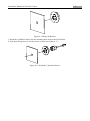
1
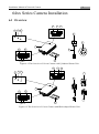
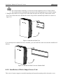
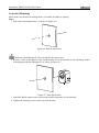
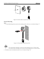
Network Camera Installation Manual (5.0.8) UD.6L0201A1187A01 31 Installation Manual of Network Camera 64xx Series Camera Installation 6.1 Overview 13 14 12 9 10 11 VIN1 AUDIO IN AUDIO OUT SD 6 8 1 18 15 LAN(PoE) RS232 ALARM RXD TXD GND IN1 1B 1A DC 12V RESET 7 2 16 17 Figure 6-1 The Overview of Covert Camera with Cylindrical Sensor Unit 13 14 12 9 10 11 4 VIN1 AUDIO IN AUDIO OUT SD 3 1 18 15 LAN(PoE) RXD TXD GND IN1 1B 1A ALARM RS232 DC 12V RESET 5 16 17 2 Figure 6-2 The Overview of Covert Camera with Block-shaped Sensor Unit 32 Installation Manual of Network Camera Table 1-8 Table 1 1 Description of the Camera No. 1 2 3 4 5 6 7 8 9 Description No. Main Unit 10 Mounting Rail 11 Block-Shaped Sensor Unit 12 Cover 13 Straight Mounting Bracket 14 Cylindrical Sensor Unit 15 RJ-12 Cable 16 Round Rail Mounting Bracket 17 POWER Indicator LED 18 Description STATUS Indicator LED LINK Indicator LED Audio Interface RJ-12 Interface Micro SD Card Slot RESET Button Power Interface PoE & Network RS-232 &Alarm Interface To reset the camera, press and hold the Reset button for at least 10 seconds when powering on or rebooting the camera. LED POWER STATUS LINK Table 1-9 LED Indicator Color& Status Indicator Solid red On normal operation Unlit Power Off Solid green Camera works properly Unlit Camera does not work properly. Flashing amber Network connection is functioning properly Unlit No network connection 6.2 Installation 6.2.1 Installation of Main Unit Steps: 1. Fix the standard mounting rail on the mounting surface. As shown in Figure 2-1. Figure 6-3 Fix the Standard Mounting Rail Installation Manual of Network Camera 33 For cement surface mounting, you need to use the expansion screw to fix the camera. For wooden surface mounting, you can just use the self-tapping screw to fix the camera. 2. Hang the hook which is on upper-side of the main unit onto the rail, press a little harder on the lower part of the main unit, and then the elastic clasp will be automatically buckled. As shown in figure 6-4 Figure 6-4 Buckle the Main Unit If you already had a standard rail to be installed, you can buckle the main unit onto the installed rail directly. Figure 6-5 Buckle the Main Unit onto Standard Rail 6.2.2 Installation of Block-Shaped Sensor Unit This series of camera support concealed mounting and exposed mounting with a decorative cover. Installation Manual of Network Camera 34 Concealed Mounting Please make sure that the mounting surface is suitable for adhesive pasting. Steps: 1. Drill on the mounting surface. As shown in Figure 6-6. Figure 6-6 Drill on the Surface Make sure the drilling hole is big enough for the camera lens. 2. Remove a side of the adhesive tape on the bracket. Paste the bracket on the mounting surface with aligning with the drilling hole. As shown in Figure 6-7. Figure 6-7 Paste the Bracket 3. Install the Block-shaped sensor unit into the bracket and make it to be buckled. 4. Tighten the fastening screw on the top of the bracket. Installation Manual of Network Camera 35 Figure 6-8 Insert the Block-shaped Sensor Unit Exposed Mounting Steps: 5. Fix the Block-shaped sensor unit on the mounting surface with screws. As shown in Figure 2-7. Figure 6-9 Fix the Block-shaped Sensor Unit For cement surface mounting, you need to use the expansion screw to fix the camera. For wooden surface mounting, you can just use the self-tapping screw to fix the camera. 6. Shield the sensor unit with the decorative cover. As shown in Figure 2-8. Installation Manual of Network Camera 36 Figure 6-10 Hood the Cover 6.2.3 Installation of Cylindrical Sensor Unit This series of camera only support concealed mounting. Please make sure that the mounting surface is suitable for adhesive pasting. Steps: 1. Drill on the mounting surface. As shown in Figure 6-11. Figure 6-11 Drill on the Surface Make sure that the drilling hole is big enough for the camera lens. 2. Remove a side of the adhesive tape on the bracket. Paste the bracket on the mounting surface with aligning with the drilling hole. As shown in Figure 6-12. Installation Manual of Network Camera Figure 6-12 Paste the Bracket 3. Install the cylindrical sensor into the mounting hole in the round rail bracket. 4. Turn the locking sleeve to fix the sensor. As shown in Figure 6-13. Figure 6-13 Install the Cylindrical Sensor 37 Installation Manual of Network Camera 38