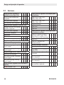
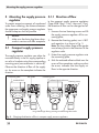
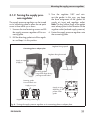
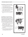
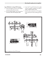
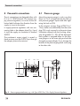
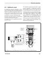
1
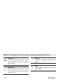
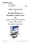
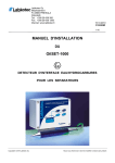
Supply Pressure Regulator Type 4708 Type 4708-5352 on Type 3730 Positioner Type 4708-1152 with filter receptacle Type 4708-6252 on Type 3372 Actuator Fig. 1: Supply pressure regulator Mounting and Operating Instructions EB 8546 EN Edition November 2012 Definition of the signal words used in these mounting and operating instructions DANGER! indicates a hazardous situation which, if not avoided, will result in death or serious injury. WARNING! indicates a hazardous situation which, if not avoided, could result in death or serious injury. 2 NOTICE indicates a property damage message. Note: Supplementary explanations, information and tips EB 8546 EN Contents 1 General safety instructions..............................................................................5 2 Design and principle of operation...................................................................6 2.1Versions.........................................................................................................8 2.2 Technical data................................................................................................9 3 Mounting the supply pressure regulator........................................................10 3.1 3.1.1 3.1.2 Compact supply pressure regulator.................................................................10 Direction of flow...........................................................................................10 Turning the supply pressure regulator..............................................................11 3.2 Supply pressure regulators for attachment to positioners and actuators..............12 4 Pneumatic connections..................................................................................16 4.1 Pressure gauge.............................................................................................16 4.2 Additional output..........................................................................................17 4.3 4.3.1 4.3.2 4.3.3 Manual/automatic switchover............................................................................ 20 Mounting on positioners................................................................................20 Mounting using an adapter plate...................................................................21 Operating the manual/automatic switchover unit............................................22 4.4 4.4.1 Filter with filter receptacle..............................................................................22 Mounting the air filter....................................................................................22 4.5 4.5.1 Rotating supplementary filter..........................................................................23 Mounting the rotating supplementary filter......................................................23 5 Set point adjustment.....................................................................................24 6 Maintenance................................................................................................24 7 Troubleshooting...........................................................................................25 7.1 Spare parts..................................................................................................25 8 Accessories..................................................................................................26 9 Dimensions in mm........................................................................................27 Note: For details on the Type 4708-45 Supply Pressure Regulator (with increased air capacity), see u EB 8546-1 EN. EB 8546 EN 3 General safety instructions 1 General safety instructions For your own safety, follow these instructions concerning the mounting, start up and operation of the device: −− The device is to be assembled, started up or operated only by trained and experienced personnel familiar with the product. According to these mounting and operating instructions, trained personnel refers to individuals who are able to judge the work they are assigned to and recognize possible dangers due to their specialized training, their knowledge and experience as well as their knowledge of the applicable standards. To avoid damage to any equipment, the following also applies: −− Proper shipping and storage are assumed. EB 8546 EN 5 Design and principle of operation 2 Design and principle of operation The supply pressure regulator is used to supply pneumatic measuring and control equipment with a constant air supply. The maximum 12 bar pressure of the compressed air network in a plant is reduced to an adjustable minimum pressure of 0.2 to 1.6 bar or 0.5 to 6 bar. At the inlet side, the supply pressure regulator is equipped with a filter cartridge with a mesh size of 20 μm. In addition, the regulator can also be equipped with a filter receptacle and a pressure gauge on the outlet side. The compressed air at the inlet flows across the filter and through the free cross-sectional area between the seat (1.1) and plug (1.2). It leaves the outlet with a reduced pressure depending on the plug position. The output pressure to be controlled is transferred through the bore (1.3) to the operating diaphragm (2) where it is converted into a positioning force. This force is used to move the valve plug depending on the force of the positioning spring (4). Turning the set point screw (7) causes the spring force to change and, as a result, the required set point is adjusted. The set point ranges of the supply pressure regulator from 0.2 to 1.6 bar and 0.5 to 6 bar are determined by various tensions of the installed positioning spring (4). Condensed water contained in the compressed air can be collected and drained when the filter cartridge (9) is mounted horizontally or the filter receptacle (12) is suspended downwards. The stopper (10) can be unscrewed or the manual drainage can be activated (drain plug (15) in old versions) to drain condensed water. 6 Note: Tighten the drain plug by hand only. The maximum permissible tightening torque is 3 Nm. EB 8546 EN Design and principle of operation Adapter plate/connecting plate Diverting gasket 1 1.1 1.2 1.3 2 3 4 5 6 7 8 9 10 11 10.1 11.1 12.1 1Body 1.1 Seat 1.2 Plug 1.3 Bore in body 2 Operating diaphragm 3 Venting bore 4 Positioning spring 5 Cap 6 Lock nut 7 Set point screw 8 Adjustment knob (accessories in section 8) 9 Filter cartridge 10Stopper 10.1 Seal 11 Bushing 11.1 Gasket 12 Filter receptacle 12.1 Gasket 13 Screw 15 Drain plug (max. 3 Nm) 16 Manual drainage 12 13 9 16 Old version 16 15 Fig. 2: Sectional drawings EB 8546 EN 7 Design and principle of operation 2.1 Versions Supply pressure regulator in standard version Type 4708- x x Aluminum filter without filter receptacle 1 0 with plastic filter receptacle 1 1 with aluminum filter receptacle 1 2 x x Supply pressure regulator in stainless steel Stainless steel filter with stainless steel filter receptacle 1 3 with plastic filter receptacle 1 4 without filter receptacle 1 7 Supply pressure regulator with adapter plate for positioner Types 3730, 3766, 3767, 3780, 3785, 3787 5 3 Types 3730, 3766, 3767, 3780, 3785, 3787 5 4 Type 4763/4765 5 5 Type 3760 5 7 Type 3761 5 8 0 Supply pressure regulator with adapter plate for pneumatic actuators G¼ 2 Type 3277 (240 to 700 cm²) with Type 3730, 3766, 3767, 3780, 3785 or 3787 Positioners ¼-18 NPT 5 Type 3372 6 2 Type 3277 Actuator with connection block 6 4 Bypass for positioner 8 2 Filter without pressure gauge Type 4708- Connection Set point range 0.5 to 6 bar/8 to 90 psi Without pressure gauge 0 with pressure gauge, completely free of copper 1 with pressure gauge, housing free of copper 2 Set point range 0.2 to 1.6 bar (3 to 23 psi) 6 2 0 0 Manual/automatic switchover x x Aluminum body and plastic filter receptacle x 0 8 3 0 Without pressure gauge 3 with pressure gauge, completely free of copper 4 Aluminum body and aluminum filter receptacle 8 4 0 with pressure gauge, housing free of copper 5 Stainless steel body and plastic filter receptacle 8 6 0 Stainless steel body and stainless steel filter receptacle 8 7 0 Supply pressure regulator with increased air capacity See u EB 8546-1 EN 8 4 5 EB 8546 EN Design and principle of operation 2.2 Technical data Supply pressure regulators Type 4708-xx Supply pressure 1 bar (15 psi) above the adjusted set point, however, at least 1.6 bar (24 psi), max: 12 bar (180 psi) Output pressure Adjustable from 0 to 1.6 bar (0 to 24 psi) or 0 to 6 bar (0 to 90 psi) Control range 0.2 to 1.6 bar (3 to 24 psi) or 0.5 to 6 bar (8 to 90 psi) ≤ 0.05 mn³/h (with 7 bar supply air) Air consumption Permissible ambient temperature (values in parentheses apply to low-temperature version) –25 to 70 °C (–50 to 70 °C) for Type 4708-11, -12, -13, -14, -45, -83, -86 –25 to 80 °C (–40 to 80 °C) for Type 4708-64 –25 to 80 °C (–50 to 80 °C) for Type 4708-10, -17, -53, -54, -55, -57, -58, -62, -82, -84, -87 (–30 °C possible, but in this case, air consumption reaches up to 0.3 mn³/h with 7 bar supply pressure) Dependency on inlet pressure < 0.01 bar/Δp = 1 bar Reversing error 0.1 to 0.4 bar (depending on set point) Hysteresis < 0.1 bar Pressure gauge Ø 40 reading range Type 4708Weight (approx. kg) Type 4708Weight (approx. kg) 0 to 1.6 bar (0 to 24 psi) or 0 to 6 bar (0 to 90 psi) Connection G 1/8 10 11 12 13 14 17 53 54 55 0.48 0.58 0.66 1.65 1.2 1.0 0.68 0.95 0.37 57 58 62 64 82 83 84 86 87 0.47 0.4 0.4 0.5 0.4 0.24 0.32 0.59 0.95 Materials Housing Metal parts Aluminum (3.3547) or stainless steel (1.4404) Plastic parts Polyamide, glass fiber reinforced Adapter plate Aluminum alloy, anodized black Stopper and gasket Cover Polyamide, glass fiber reinforced and NBR Polyamide, glass fiber reinforced Cover Polyamide, glass fiber reinforced Plug Polyamide, glass fiber reinforced and polyoxymethylene Plug seal NBR and VMQ Diaphragm NBR Diaphragm plate Polyamide, glass fiber reinforced Filter cartridge Pressure gauge 20 μm: polypropylene · 5 μm: stainless steel · Replacement filter 5 μm: stainless steel Housing Connection EB 8546 EN Stainless steel Stainless steel (copper-free version) Nickel-plated brass 9 Mounting the supply pressure regulator 3 Mounting the supply pressure 3.1.1 Direction of flow regulator In the compact supply pressure To prevent excessive amounts of condensed water from collecting, the distance between the compressor and supply pressure regulator should be kept as short as possible. NOTICE Make sure the drain plug faces downwards in versions with filter receptacle. 3.1 Compact supply pressure regulator The supply pressure regulator can either be mounted directly in the air supply pipeline or on rails or brackets using the corresponding mounting parts (see accessories in section 8). Observe the direction of flow of the supply air. An arrow on the nameplate indicates the direction. Flat gasket Connecting plate Standard label 4708-112. 3-.... 0 6 G Supply pressure regulator regulators (Type 4708-10xx/-11xx/-14xx and -17xx), the direction of flow can be changed as follows: 1. Unscrew the two fastening screws and lift the supply pressure regulator off its connecting plate. 2. Remove the diverting gasket, turn it 180° and reposition it as shown in Fig. 3. Note: The long rubber finger of the gasket must always point in the direction of the regulator outlet. 3. Fasten the supply pressure regulator onto the connecting plate. 4. Stick the enclosed adhesive label over the arrow of the nameplate, making sure that the arrow indicates that the supply air flows in the opposite direction. Connecting plate Adhesive label with arrow 4708-112. 3-.... 0 Fastening screws G 6 Long rubber finger always pointing towards the regulator outlet Fig. 3: Changing the direction of flow in compact supply pressure regulators 10 EB 8546 EN Mounting the supply pressure regulator 3.1.2 Turning the supply pressure regulator The supply pressure regulator can be turned on its connecting plate to allow the set point screw to face either up or down. 1. Unscrew the two fastening screws and lift the supply pressure regulator off its connecting plate. 3. Turn the regulator 180° and reinsert the gasket. In this way, you keep the bore assignment of the gasket for supply air input and regulator outlet. Note: The long rubber finger of the gasket must always point in the direction of the regulator outlet (reduced supply pressure). 4. Fasten the supply pressure regulator onto the connecting plate. 2. Pull the diverting gasket out of the regulator and keep it in this position. Regulator facing upward Connecting plate or adapter plate Regulator facing downward Supply air input (Supply) > Fastening screws Diverting gasket Long rubber finger always pointing towards outlet Regulator outlet Diverting gasket Front and back view Supply air input Supply air input depending on the position of the gasket Regulator outlet (long rubber finger) Fig. 4: Turning the supply pressure regulator on its connecting plate or adapter plate EB 8546 EN 11 Mounting the supply pressure regulator 3.2 Supply pressure regulators for attachment to positioners and actuators The supply pressure regulator versions intended for attachment to positioners and actuators are equipped with various adapter plates for the attachment. Type 4708-54xx has a second output sealed with a stopper. This is intended for reduced supply air. It can be used to supply a second device, if required (e.g. a pilot-operated solenoid valve). Type 4708-53xx If required, the installation position of the supply pressure regulator can be changed by turning it 180° on its adapter plate to allow the set point screw to face either up or down. This applies particularly to positioners that can be attached either to the left or right side of the valve yoke to determine the operating direction and fail-safe action of the actuator. To turn the supply pressure regulator, proceed as described in section 3.1.2 for the compact supply pressure regulators. The regulator is turned on its adapter plate instead of on the connecting plate. 2. Place the supply pressure regulator on the positioner on the side where the pneumatic connections SUPPLY and OUTPUT are located. Screw tight using the two M5 screws (3). Type 4708-54xx for rotary actuators Proceed to mount as Type 4708-53xx. 12 111 1. Insert the gasket (2) into the recess of the adapter plate (1). Type 4708-54xx 194 Supply pressure regulator for Type 3730, 3766, 3767, 3780, 3785 or 3787 Positioner Type 4708-53xx for Type 3271 Actuator and Type 3277 Actuator 120, 240 to 700 cm² with hooked-up valve accessories 73 Fig. 5: Attachment on positioners EB 8546 EN Mounting the supply pressure regulator Type 4708-55xx for Type 4763 and Type 4765 Positioners 3. Screw the special nuts (5) into the connecting holes of the positioner. 6. Seal the spare connections with stoppers (4) to prevent dirt from entering the device. 4. Insert the gasket (2) into the recess of the adapter plate (1). 0 5. Push the special hollow screws (6) for SUPPLY and (7) for OUTPUT into the connecting holes of adapter plate (1). SAMSON 4763 6 0 4708-552. 6 1 6. Place the supply pressure regulator onto the positioner and fasten it using the two special screws. 1 7 5 2 7. Seal the spare connections with stoppers (4) to prevent dirt from entering the device. 5 4 Type 4708-57xx for Type 3760 Positioner 6 The attachment for a positioner mounted on the left side of the valve yoke (looking onto the black switchover plate) is shown. For a positioner mounted on the right side, the adapter plate is attached in the same way, except the supply pressure regulator must be turned by 180° (see Seite 30 bottom). 1. Screw the special nuts (5) into the connecting holes of the positioner. Switchover plate 1 1 7 2. Insert the seals (9) into the recess of the adapter plate (1). 3. Push the special hollow screws (6) for SUPPLY and (7) for IN.SIGNAL into the connecting holes of adapter plate (1). 4. Place the supply pressure regulator onto the positioner and fasten it using the two special screws. 10 5 9 5 4 6 Fig. 6: Attachment on positioners 5. Seal the IN. SIGNAL connection of the positioner using the stainless steel stopper (10). EB 8546 EN 13 Mounting the supply pressure regulator Type 4708-58xx for Type 3761 Positioner 7. Screw the special nut (5) into the SUPPLY connecting hole of the positioner. 5 6 4 3 S 0 2 1 8. Push the special hollow screw (6) into the connection hole of the adapter plate (1). Input 27 Output 238 1 G 9. Insert the O-ring (9). Position the supply pressure regulator and fasten it to the positioner using the special screw. Output 138 10.Seal the spare connections with stoppers (4) to prevent dirt from entering the device. 5 6 9 1 4 Type 4708-64xx for Type 3277 Actuator Before attaching the supply pressure regulator, check whether the tongue of the gasket (1.2) is aligned at the connection block (1) in such a way that the actuator symbol (1.3) indicating “Actuator stem extends” or “Actuator stem retracts” matches the fail-safe action of the actuator. If this is not the case, proceed as follows: 3 G3/8 1. Unscrew the three Phillips screws (3.1), lift off the cover plate (1.1) and turn the gasket (1.2) by 180° and reinsert it. 2. Place the connection block with inserted O-ring on the positioner and actuator yoke and fasten it with hexagonal socket screw (3). 3. Place the supply pressure regulator with O-ring on the connection block and fasten it with hexagonal socket screw (2). 3.1 2 1 1 1.1 1.2 1.3 3.1 Fig. 7: Attachment of supply pressure regulator 14 EB 8546 EN Mounting the supply pressure regulator Type 4708-62xx for Type 3372 Actuator 4. Screw the special nut (5) into the SUPPLY connecting hole of the actuator. 5. Push the special hollow screw (6) into the connection hole of the adapter plate. 6. Insert the O-ring (9). Position the supply pressure regulator and fasten it to the actuator using the special screw. 7. Seal the spare connections with stoppers (4) to prevent dirt from entering the device. 1 6 5 9 4 1 9 5 4 6 Fig. 8: Attachment to Type 3372 Actuator EB 8546 EN 15 Pneumatic connections 4 Pneumatic connections 4.1 Pressure gauge The air connections are designed either with G ¼ or ¼-18 NPT threads. On compact supply pressure regulators, an arrow on the adhesive label indicates the direction from the supply air input to the output. Mount the pressure gauge in such a way that there is a 2 to 3 mm gap between the lock nut and pressure gauge's square end after tightening the lock nut (20). In the compact versions (Type 4708-12xx/13xx), make sure additionally that the screw plug (23) is only screwed in to the point where it becomes aligned with the housing, otherwise the gaskets (21, 22) will be damaged. Each gasket is assigned either to the pressure gauge or to the screw plug and must be changed correspondingly if you change the location of the pressure gauge and screw plug to the other side. In supply pressure regulators with two connecting holes in the adapter plate (Fig. 5 and 6, top), the supply air connection is marked SUPPLY. The positioner's output signal is routed in these versions over the OUTPUT port through the adapter plate to the actuator. 20 2...3 mm 21 22 23 0 mm Fig. 9: Pressure gauge attachment, e.g. with Type 4708-12xx/13xx Supply Pressure Regulators 16 EB 8546 EN Pneumatic connections 4.2 Additional output An additional output for reduced air pressure is required to allow the supply pressure regulator to supply two pneumatic devices. In some versions of Type 4708 (see section 8 on accessories), a second output can be made available by using an intermediate plate. Example: Pneumatic actuator with positioner and pilot-operated solenoid valve à Supply air must be supplied separately to the pilot control. The reduced supply pressure of the supply pressure regulator is additionally routed to the threaded connection at the side over the corresponding holes in the intermediate plate. All supply pressure regulators have the same intermediate plate, except for Type 470857xx, designed for attachment to Type 3760 Positioner (Fig. 12). Its intermediate plate has a different hole assignment for the air ducts. All versions can be ordered made of aluminum or stainless steel and with either G or NPT threads. See section 8. 1 Output for reduced supply air 1.1 E SUPPLY A 2 2.1 A E 3 Intermediate plate (2) with additional connection A E 4 A 4.1 E Fig. 10:Mounting an intermediate plate for Types 3730, 3766, 3767 and 3780 Positioners EB 8546 EN 17 Pneumatic connections Mounting the intermediate plate Note: 1. Remove the fastening screws and lift the supply pressure regulator (4) together with the diverting gasket (3) off the adapter plate (1). Make sure you do not change the position of the diverting gasket in the supply pressure regulator. Note: The long rubber finger of the diverting gasket must always point in the direction of the regulator outlet (reduced supply pressure, see Fig. 10, 11 and 12). 2. Insert O-rings (2.1) in the holes of the intermediate plate (2). 3. Place the intermediate plate onto the connecting plate or adapter plate in such a way that the three holes located next to Supply air input 1.1 1 2 Output 2.1 Reduced air E A AM A E A A E 3 4 4.1 A E Fig. 11:Mounting an intermediate plate on Type 3372 Actuator 18 EB 8546 EN Pneumatic connections one another are positioned over both 5 mm holes on the adapter plate and the bores (1.1) for the fastening screws are aligned. 4. Place the supply pressure regulator (4) with the diverting gasket (3) onto the intermediate plate (2). Insert the longer fastening screws and fasten the parts. 1 1.1 SUPPLY AM A E Intermediate plate (2) 2 A E 2.1 A 3 E A 4 E A 4.1 Fig. 12:Mounting an intermediate plate for Type 3760 Positioner EB 8546 EN 19 Pneumatic connections 4.3 Manual/automatic switchover 4.3.1 Mounting on positioners The positioner output is routed to the actuator over the manual/automatic switchover. In automatic mode, the positioner is in closed-loop operation. In manual mode, the output pressure of any supply pressure regulator is directly applied to the actuator. This creates a manual bypass of the positioner. The manual/automatic switchover unit is mounted directly onto Types 376x, 378x and 373x (Fig. 14) or on an adapter plate with hook-up to the actuator (Fig. 13). The Type 4708-53 (Fig. 15) or Type 470854 Supply Pressure Regulator can be directly mounted. All other supply pressure regulators can be connected to the manual/automatic switchover unit using piping (hook-up). Output (38) Fig. 13:Mounting on positioners −− Insert flat gasket into recess of the manual/automatic switchover unit (Fig. 14). −− Fasten the manual/automatic switchover unit to the positioner using the two hexagonal socket screws. −− Connect hook-up to the SUPPLY and OUTPUT connections of the manual/automatic switchover unit. Output Supply Supply (9) 2 1 4 Legend 1 Pneumatic control valve with positioner 2 Adapter plate 1400-9605 (G) 1400-9606 (NPT) 3 Type 4708-82 Manual/automatic Switchover in AUTO mode 4 Supply pressure regulator with filter (e.g. Type 470810) 3 Fig. 14:Mounting the manual/automatic switchover using an adapter plate 20 EB 8546 EN Pneumatic connections Optionally, a Type 4708-53 Supply Pressure Regulator can be mounted upstream of the manual/automatic switchover unit (Fig. 15). 4.3.2 Mounting using an adapter plate −− Fasten adapter plate, for example to a NAMUR rib using a hexagonal socket screw. −− Fit the gasket on the manual/automatic switchover unit. Fasten it to the adapter plate using the two hexagonal socket screws. Fig. 15:Manual/automatic switchover with Type 4708-53 Supply Pressure Regulator with pressure gauges and rotating filter receptacle EB 8546 EN Fig. 16:Mounting using an adapter plate −− Connect hook-up for positioner and actuator as shown in Fig. 13. 21 Pneumatic connections 4.3.3 Operating the manual/ automatic switchover unit In normal operation, the manual/automatic switchover runs in automatic mode, during which the positioner supplies air to the pneumatic actuator. Fig. 17:Cap and switchover pin To switch to manual mode, twist off the plastic cap. Turn the switchover pin counterclockwise and pull it (approx. 1 cm) out of the bayonet lock. The compressed air is then routed directly from the supply pressure regulator or from the air supply network to the pneumatic actuator. To switch back to automatic mode, push in the switchover pin again. To do this, insert the lock pin completely into the bayonet and lock it. 4.4 Filter with filter receptacle The Types 4708-83, 4708-84, 4708-86 and 4708-87 Air Filters are designed for universal use. They have either G ¼ or ¼-18 NPT threaded connection. Fig. 18:Types 4708-83 to -87 Air Filters 4.4.1 Mounting the air filter Mount the air filter directly into the pipeline, while ensuring the direction of flow (printed on the device) is kept. NOTICE The filter receptacle must face downwards to function correctly. Replace plastic cap and tighten. 22 EB 8546 EN Pneumatic connections 4.5 Rotating supplementary filter 4.5.1 Mounting the rotating supplementary filter The rotating supplementary filter (see Fig. 15) is designed for mounting to Type 4708-53 and Types 4708-55 to -63 Supply Pressure Regulators. It replaces the small integrated filter cartridge. The entire filter housing can be rotated by 360° to ensure that the condensate drain is always facing downwards. −− Remove the cover and filter cartridge from the supply pressure regulator. Filter versions −− Place the supplied seal carefully onto the groove (see arrow) of the connection. −− Insert connecting pipe together with seal into the supply pressure regulator and tighten the plastic coupling nut. Aluminum body with filter in transparent plastic receptacle Temperature range: –25 to 70 °C Order no. 1400-9460 Special version Temperature range: –50 to 70 °C Order no. 1400-9461 Fig. 19:Connection and seal for supplementary filter Note: Make sure that the seal does not fall out of the groove during mounting, otherwise the filter will not function properly. −− Adjust the direction of the supplementary filter until it is upright. −− Secure the position by tightening the hexagonal socket screw (6 mm). EB 8546 EN 23 Set point setting 5 Set point setting 6 Maintenance (Fig. 2) (Fig. 2) Depending on the version, the set point of the supply pressure regulator can be adjusted either at the adjustment knob (8), or after screwing off the cap (5), at the set point screw (7). We recommend to check the filter as often as possible. Drain condensed water that has collected: −− Turning the knob or screw clockwise increases the output pressure and turning it counterclockwise reduces the output pressure. −− Lock the setting with the lock nut (6). Note: When using the version with the adjustment knob (8) to adjust the set point, make sure that the Phillips screws are screwed tight to prevent the knob from coming loose due to vibration. −− Remove the stopper (10) or −− Unscrew the drain plug (15) by about half a turn or −− Activate the manual drainage (16). Note: Tighten the drain plug by hand only. The maximum permissible tightening torque is 3 Nm. In case of malfunction, e.g. due to a drop in pressure, unscrew the stopper (10) or the filter receptacle (12) and replace the filter cartridge (order no. 8504-9027). Prior to carrying out any maintenance work, shut off the air supply! In the version with a filter receptacle, tighten the fastening screw (13) to allow the filter cartridge to sit properly. Replace the gasket (12.1, order no. 04390061), if necessary. In Types 4708-11xx/-14xx, do not unscrew the bushing (11), if at all possible. If, however, you needed to unscrew it, replace the gasket (11.1, order no. 0439-0287) as well. If there is any leakage at the stopper (10), the entire stopper including the seal (10.1) must be replaced. Refer to section on spare parts. 24 EB 8546 EN Troubleshooting 7 Troubleshooting −− Leakage between supply pressure regulator and adapter plate: Check whether the diverting gasket (Fig. 3 and Fig. 4) is installed and the two fastening screws are tightened properly. −− Excessive blow-off over the venting bore (3, Fig. 2): Check whether the diverting gasket (Fig. 3 and 4) is installed correctly. −− Air capacity drops and the output pressure drops: Check the filter cartridge (9, Fig. 2) for dirt and make sure the set point is correctly adjusted. 7.1 Spare parts Article Order numbers Filter Filter cartridge 20 µm Filter cartridge 5 µm including gasket Filter cartridge 5 µm, sintered stainless steel 8504-9027 8504-9030 1400-9609 Filter receptacle Filter receptacle, plastic Filter receptacle, aluminum Filter receptacle, stainless steel 1199-0423 1199-0424 1199-0425 Filter compatible with paint on request Gasket for filter receptacle 0439-0061 Stopper including seal (Fig. 2, 10 and 10.1) 1099-5055 Pressure gauge Pressure gauge, entirely made of stainless steel Pressure gauge, made of brass/stainless steel 0089-0009 0089-0018 Pressure gauge seal 1099-4305 EB 8546 EN 25 Accessories 8 Accessories Accessories Order no. Mounting parts for rail mounting according to EN 50022 Mounting parts for rail mounting according to EN 50035 1400-7341 1400-7342 Mounting parts for mounting on bracket for Type 3271 or Type 3277 Actuators 1400-7343 Intermediate plate for additional connection with Types 4708-10xx/-11xx/-53xx/-55xx/-58xx/62xx (not required for Type 4708-54xx) Aluminum with G ¼ thread Aluminum with ¼ NPT thread Stainless steel with G ¼ thread Stainless steel with ¼ NPT thread 1400-7400 1400-7404 1400-7402 1400-7406 Intermediate plate for additional connection with Type 4708-57xx Supply Pressure Regulator Aluminum with G ¼ thread Aluminum with ¼ NPT thread Stainless steel with G ¼ thread Stainless steel with ¼ NPT thread 1400-7401 1400-7405 1400-7403 1400-7407 Special screw to mount Type 4708-54xx on Type 3710 Reversing Amplifier 1400-7806 Adjustment knob for set point adjustment 1400-7408 Nut for panel mounting 1400-7725 Adapter plate for manual/automatic switchover (Type 4708-82) Aluminum with G ¼ thread Aluminum with ¼ NPT thread Stainless steel with G ¼ thread Stainless steel with ¼ NPT thread 1400-9605 1400-9606 1400-9607 1400-9608 Adapter plate (from Type 3710) to mount Type 4708-53 on all old versions of Types 3766, 3767 or 3780 Positioner 1400-9621 Replacement filter cartridge 5 µm, sintered stainless steel 1400-9609 26 EB 8546 EN Dimensions in mm 9 Dimensions in mm Types 4708-10xx/-17xx Supply Pressure Regulators 39 43 52 Types 4708-11xx/-14xx Supply Pressure Regulators 79 43 52 79 51 51 19 19 78 (102) 182 (206) 126 60 44 Mounting bracket (accessories) 60 44 Supply pressure regulator with intermediate plate 90 EB 8546 EN The overall height increases by 24 mm when the additional connection is used. In this case, the dimensions in parentheses () apply. 27 Dimensions in mm Types 4708-12xx/-13xx Supply Pressure Regulators 59 42 Type 4708-83xx/-84xx/-86xx/-87xx Filter 99 59 44 44 12 42 15 Ø41 102 123 116 Type 4708-53xx Supply Pressure Regulator for Type 3730, 3766, 3767, 3780, 3785 or 3787 Positioner 65 (89) 14 80 0 6 70 25 6 4708-535. 0 51 7 22.5 NPT Output Supply 28 EB 8546 EN Dimensions in mm Type 4708-54xx Supply Pressure Regulator for Type 3730, 3766, 3767, 3780, 3785 or 3787 Positioner Output Output Reduced supply air Supply 66 111 192 19 73 3 96 Type 4708-55xx for Type 4763 or 4765 Positioner Output 27 0 6 122 SAMSON 4763 0 4708-552. 6 55 EB 8546 EN 66 (90) Supply 29 Dimensions in mm Type 4708-57xx Supply Pressure Regulator for Type 3760 Positioner Input Signal Supply 122 Supply Input Signal 99 133 (157) 30 47 122 EB 8546 EN Dimensions in mm Type 4708-58xx for Type 3761 Positioner 111 Supply SAMSON 30 2 5 6 4 3 S 0 1 93 60 (84) 27 Input G 56 238 Output 138 Output Type 4708-64xx for Type 3277 Actuator Left or right attachment 179 125 103 37 111 G3/8 113 Supply 97 40 122 74 EB 8546 EN 31 Dimensions in mm Type 4708-6221 for Type 3372-031x Actuator 113 Supply 111(135) 94 G 19 6 4708-622X 0 60 113 Supply Type 4708-82 Manual/automatic switchover with adapter plate 70 56 28 46 13 50 82 10 56 32 24 EB 8546 EN Dimensions in mm EB 8546 EN 33 Weismüllerstraße 3 · 60314 Frankfurt am Main · Germany Phone: +49 69 4009-0 · Fax: +49 69 4009-1507 Internet: http://www.samson.de EB 8546 EN 2013-05-17 SAMSON AG · MESS- UND REGELTECHNIK