1
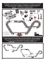
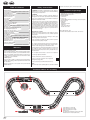
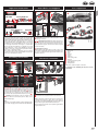
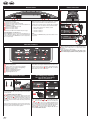
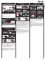
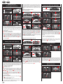
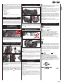
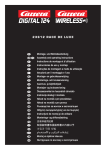
30166 DTM Challenge Montage- und Betriebsanleitung Assembly and operating instructions Instructions de montage et d’utilisation Instrucciones de uso y montaje Instruções de montagem e modo de utilização Istruzioni per il montaggio e l’uso Montage- en gebruiksaanwijzing Monterings- och bruksanvisning Asennus- ja käyttöohjeet Montajse- og bruksanvisning Ősszeszerelési és használati útmutató Instrukcja obsługi i montażu Návod na montáž a pre prevádzkuo Návod na montáž a pro provoz Ръководство за монтаж и експлоатация Οδηγίες συναρμολόγησης και λειτουργίας Instrucţiuni de montaj şi de utilizare Monterings- og driftsvejledning 安装和使用说明 取扱説明書取扱説明書の内容は予 조립과 작동 방법 Montaj ve işletme kılavuzu Инструкция по монтажу и эксплуатации Verpackungsinhalt · Contents of package · Contenu du carton · Contenido de la caja · Conteúdo da embalagem · Contenuto della confezione · Verpakkingsinhoud · Innehållet i förpackningen Pakkauksen sisältö · Innholdet i pakningen · A csomag tartalma · Zawartość opakowania Obsah balenia · Obsah balení · Съдържание на опаковката · Περιεχόμενα συσκευασίας Conţinutul ambalajului · Emballageindhold · 包装内容 · 梱包内容 · 포장내용물 · Ambalaj içeriği · Содержимое картона 30166 DTM Challenge 1x 2x 1x 1x 11x A 10x 1x C B 1x 4x 2x 1x 4x 34x 6x 56x 6x D 2x E F B C A C C G C H D E B C C B E C B B B F C B E B B “DTM” is a trademark, licensed by ITR e.V. D The BMW logo, the BMW word mark and the BMW model designation are trademarks of BMW AG and are used under license. „Mercedes-Benz“, and the design of the enclosed product are subject to intellectual property protection owned by Daimler AG. They are used by Stadlbauer Marketing + Vertrieb GmbH under license. E C B B 4x 60°/44 cm/17.32 inch F C 1x 120°/88 cm/34.64 inch F F G 1x 240°/168 cm/66.14 inch H Ausbauvorschläge · Proposals for extension · Suggestions d‘extension · Propuestas de ampliación Propostas de expansão · Proposte di ampliamento · Uitbreidingsvoorstellen · Monteringsförslag Rakennelmaehdotuksia · Strekningsforslag · Kiépítési javaslatok · Propozycje rozbudowy Návrhy výstavby · Návrhy výstavby · Предложения за демонтаж · Προτάσεις επέκτασης Propuneri de asamblare · Udvidelsesforslag · 多项扩充建议 · 拡張提案 · 기타 조립 예 · Genişletme önerileri · Предложения по расширению 30166 + 30345 + 20601 + 10109 CHANNEL SET 30166 + 30367 2 Table of contents Safety instructions Contents of package Technical advice for assembly Important Information Assembly instructions Guard Rails and Supports Electrical connection Car components Connections Control elements Preparation of start Encoding/programming of cars to the according speed controllers Points function Light function on/off Operating 6 cars Encoding/programming of Autonomous Car Encoding/programming Pace Car Setting of the cars´ basic speed Setting of cars´ braking performance Setting fuel tank capacity Extended Pit Lane function Sound ON/OFF Reset function Energy-saving mode Car programming from Digital 132 to Evolution (analogue) Replacement of double sliding contact and guide keel Changing the rear axle Maintenance and care Troubleshooting/Driving tips Technical specifications condition. Assembly may only be carried out by an adult. Safety instructions 10 10 10 11 11 11 11 11 12 12 12 12 12 13 13 13 13 13 14 14 14 14 14 15 15 15 15 15 15 15 Welcome Welcome to the Team Carrera! These operating instructions contain important information regarding the assembly and operation of your Carrera DIGITAL 132 racetrack. Please read them carefully and keep them in a safe place afterwards. If you have any queries, please do not hesitate to contact our distributor or visit our websites: carrera-toys.com Please check the contents for completeness and possible transport damage. The packaging contains important information and should also be retained. We hope you will derive a lot of pleasure from your new Carrera DIGITAL 132 track. • WARNING! Not suitable for children under 36 months. Danger of suffocation due to small parts which may be swallowed. Warning: risk of pinching caused by function. • WARNING! This toy contains magnets or magnetic components. Magnets attracting each other or a metallic object inside the human body may cause serious or fatal injuries. Seek medical attention immediately if magnets are swallowed or inhaled. • The transformer is not a toy! Do not short-circuit the transformer’s connections! Note to parents: Regularly inspect the transformer for damage to the cable, plug or housing! Only operate the toy with recommended transformers! The transformer may no longer be used if it is damaged! Only operate the racetrack with a transformer! If play is interrupted for longer periods, it is recommended to separate the transformer from the power supply. Do not open transformer or speed controller housings! Important note to parents: Transformers and power supply units are not suitable to be used as toys. The use of such products needs to be constantly supervised by the parents. Contents of package 1 AMG Mercedes C-Coupe DTM “D.Coulthard, No.19” 1 BMW M3 DTM “M.Tomczyk, No.1” 11 Standard straights 1 Control Unit 10 Curves 1/60° 1 Carrera DIGITAL 132 double lane change section (2 track parts) 2 Speed controllers 1 Transformer Guardrails Replacement contacts Instructions Track section interlocks Shoulder end sections Track length: 26.24 ft. / 8,0 m Dimensions when assembled: 10.53 x 4.99 ft. / 321 x 152 cm • Regularly check the track and cars for damage to cables, plugs and housings! Replace defective parts. • The car racetrack is not suitable for outdoor operation or operation in wet locations! Keep away from liquids. • Do not place any metal parts onto the track to avoid short-circuits. Do not place the track in the immediate vicinity of delicate objects, as these could be damaged by cars hurled from the track. • Pull the plug before cleaning the racetrack! Only use a damp cloth for cleaning, no solvents or chemicals. When it is not in use, store the track in a dry and dust-protected location, preferably in the original cardboard box. • Do not operate race track at face- or eye-level – risk of injury due to cars being catapulted off the track. • Misuse of transformer can cause electrical shock. • The toy is only to be connected to Class II equipment bearing the following symbol. • The toy must only be used with a transformer for toys. Note: The vehicle may only be operated again in a completely assembled Technical advice for assembly 2 3 4 1 10 1 2 3 4 Connecting track + Control Unit Double lane change section input Double lane change section output Infrared sensor: The infrared sensor MUST be located on the switch that functions as the entry rail (dark diode). Important Information Guard Rails and Supports 1 EVOLUTION Car components 2 1 Carrera DIGITAL 132 3 4 3 8 Carrera DIGITAL 132 3 EVOLUTION 2 10 Please note that Evolution (analog system) and Carrera DIGITAL 132 (digital system) involve two separate and completely independent systems. We hereby expressly indicate that both systems must be kept separate when setting up the track, i.e. no connecting rail from Evolution may be used together with the connecting rail and Black Box of the Carrera DIGITAL 132, even if only one of the two connecting rails (Evolution connecting rail or Carrera DIGITAL 132 connecting rail and Black Box) is attached to the current supply. Furthermore, no other Carrera DIGITAL 132 components (switches, electronic lap counter, Pit Lane) may be built into an Evolution course, i.e. via analog operation. Non-compliance with the above information may result in damage or destruction of the respective Carrera DIGITAL 132 components. In this case no warranty may be claimed. 2 + 3 Supporting raised sections: The shank of the ball pivot is to be inserted into the square slots provided on the underside of the track. The supports can be made higher by using the extensions. The pedestal of the supports can be screwed to a base if required (screws not included). 4 Supporting steep curves: Slanting supports of the right height are provided to support steep curves. Fix the nonadjustable supports at the beginning and end of the curves. Insert the heads of the supports in the round slots of the underside of the track. 4 Electrical connection 1 2 3 4 9 3 5 1 Guard rails: Guard rail mounts are fitted by tilting them upwards onto the verge of the track. Assembly instructions 1 11 6 7 1 2 3 4 5 6 7 8 9 10 11 Body, spoiler Engine Tyres Rear axle Chassis Guide keel Double sliding contact Front axle Car board with reversing switch Front light board Rear light board Note: vehicle construction depends on the model. The designation of the individual parts may not be used as order numbers. 3 2 1 + 2 + 3 Before assembling please insert the connecting clips in the track as shown in figure 1 . Stick tracks together on a flat base. Move the connecting clips according to figure 2 in direction of the arrow until they audibly snap in. The connecting clip may also be inserted later. The connecting clips can be removed into both directions by simply pressing down the clamped nose (see fig. 3 ). 4 Fastening: To fasten the track sections on a board, it is neces- sary to use the track section fasteners (Item no. 85209, not contained in the package). Note: Carpeting is not a suitable foundation on which to build the track because of static charging, formation of fluff and ready inflammability. 1 Connect the transformer plug with the Control Unit. 2 Connect the enclosed speed controllers to the Control Unit. Note: To avoid short-circuits and electrocution, the toy may not be connected using foreign devices, plugs, cables or other objects foreign to this toy. The Carrera Digital 132 car racetrack only works properly with an original Carrera Digital 132 transformer. The PC interface (PC Unit) may only be operated together with the original Carrera PC Unit. 11 Points function Connections 1 1 2 3 4 5 6 7 Additional wired speed controllers may be plugged into connectors 3 and 4. Please note that these will use address 5 and 6 then. Connections (from left to right): 1 Connection for Lap Counter 30342 2 Connection for PC-unit or Lap Counter 30355 3 Connector 1 for speed controller, speed controller extension set or wireless+ receiver 4 Connector 2 for Wireless Tower 10108 5 Connector 3 for speed controller 6 Connector 4 for speed controller 7 Connection for DIGITAL 124 / DIGITAL 132 power supply 2 Using the speed controller extension set 30348 it has to be plugged into connector 1. The cars´ addresses will be allocated as follows: • • • • General information on connectors 1-4: When a WIRELESS+ receiver is used, it must be plugged into connector 1. Optionally a Wireless Tower 10108 can be plugged into connector 2. When only the WIRELESS+ receiver is used, connector 2 is to be left empty. Speed controller extension set = address 1, 3 and 4 connector 2 = address 2 connector 3 = address 5 connector 4 = address 6 Note: a combination of wireless and speed controller extension set is not possible! Control elements 1 Make sure that the car’s guide keel is located inside the track slot and that the double sliding contact is in contact with the current carrying track. Place the cars onto the connecting track. 2 When changing lanes, you must keep the button on the speed controller depressed until the car has passed the point. 1 2 3 4 5 6 7 8 4 3 5 6 2 7 4 5 2 Encoding/programming of cars to the according speed controllers 3 6 This Carrera Digital 132 vehicle ideally matches the Carrera track system scale 1:24. 1 + 2 Optimally setting up the grinders: To ensure proper and continuous driving, slightly fan out the ends of the contact brushes 1 and bend them towards the track as per fig. 2 . Only the end of the contact brush should have contact to the track and may be cut off slightly in case of wear. Dust and abrasion should be removed from track material and sliding contacts from time to time. During operation small car parts as spoilers or mirrors may get off or brake due to being original detailed parts of the car model. To avoid this it is possible to remove them before operation. 12 8 General operating information Some buttons are assigned with different tasks. In order to set a function you need to use key combinations. Any programming steps can be cancelled with button 4 “ESC/PACE CAR″. You will find further details in the course of this manual. On/off switch Switch for fuelling function Button to start the race / acknowledge programming Button for Pace Car / termination of programming Button for setting basic speed Button for setting braking performance Button for setting fuel tank capacity Programming button for cars Preparation of start 1 1 2 1 1 2 1x 8 7 3 4 To encode a car place it on the track and swich on the Control Unit. Press “Code” button once 8 , fig. 1 ; the first LED starts to light, fig. 2 . Then push lane-change-button once on the relevant speed controller, fig. 3 . In case the car is equipped with lights they will start to flash and the Control Unit´s LEDs 2-4 will light successively. Once encoding has been carried out the middle LED lights permanently (fig. 4 ) and the car is allocated to the speed controller. Note: This kind of encoding requires to only have the car on the racetrack which shall be encoded. Encoding/programming Pace Car Light function on/off Setting of the cars´ basic speed 1 – 10 1 1 – 10 2 Pit Lane 30356 3 sec. STOP 4 3 5 6 2 1 1 2 3 The car programmed to the speed controller will have to come to a stop for at least 3 seconds before the light can be switched on or off by the push of the lane-change-button. 4 3 4 3 2 5 150 100 200 50 0 250 6 SPEED + CLICK 7 Encoding/programming of Autonomous Car 2 1 1 2 2x 8 7 3 5 6 6 8 4 300 5 Plug speed controller extension set (item no. 30348) in connector 1 of the Control Unit. For next steps see section “Coding of cars to the according speed controller“. 5 1 5 5 Note: applies only to models fitted with lighting Operating 6 cars 3 4 3x 8 7 (only in combination with Pit Stop Lane #30356) Switch on the Control Unit, place the car to be encoded on the track and press “Code″ 8 three times, fig. 1 . The first three LEDs at the Control Unit start to light, fig. 2 . Now push the lane-change button at the speed controller, fig. 3 ; LEDs 2-5 will light successively. Wait until the middle LED lights again, fig. 4 . Activate the speed controller´s tappet until the car has reached the desired speed. Now push lane-change button again, fig. 5 . The Pace Car´s encoding is completed now and the car enters the Pit Stop Lane. Note: This kind of encoding requires having only the car on the track which is to be encoded. The programming of the Pace Car will be maintained unless the car is not being recoded. The Pace Car is always displayed with address 8 in combination with the Position Tower. 3 2 1 The setting of the basic speed can be effected individually for one and/or several cars. The cars which are to be adjusted have to be 6 track. The setting can 7 be carried out on 810 levels positioned on the with the 5 LEDs indicating the different levels by flashing or permanent lighting. 1 1 LED lights = low speed 2 5 LEDs light = high speed Switch on the Control Unit, place the cars to be adjusted on the track and press “SPEED” 5 once. A certain number of LEDs will now light, showing the speed level last used. Push the “SPEED” button 5 as many times until you have reached the speed desired. Confirm by pressing “ENTER/START” 3 . A short running light and the lighting of the middle LED confirms completion of the setting, fig. 6 . Extended Pace Car function After the Pace Car´s encoding has been completed it will automatically enter the Pit Lane during the first laps. In order to start the Pace Car please push the button “Pace Car” 4 once. The LEDs 2 and 3 at the Control Unit will light and the Pace Car will leave the Pit Lane. The Pace Car will now drive as long as the button „Pace Car“ is pushed again. LED 2 stops lighting and the car automatically enters the Pit Lane within the current lap. 4 150 100 200 50 0 250 SPEED + CLICK 300 Switch on the Control Unit, place the car to be encoded on the track and press „Code“ 8 twice, fig. 1 . The first two LEDs at the Control Unit start to light, fig. 2 . Now push the lane-change button at the speed controller, fig. 3 ; LEDs 3-5 will light successively. Wait until the middle LED lights again, fig. 4 . Activate the speed controller´s tappet until the car has reached the desired speed. Now push lane-change button again, fig. 5 . Autonomous Car´s encoding is completed now. Note: This kind of encoding requires having only the car on the track which is to be encoded. The programming of the Autonomous Car will be maintained unless the car is not being recoded. The Autonomous Car is always displayed with address 7 in combination with the Position Tower. 13 When driving in “REAL-mode” the car with a full tank is “heavier”, drives slowlier and shows a lower braking effect; a car with an empty tank is “lighter”, drives faster and shows a higher braking effect. The current fuel tank capacity and the “fuel consumption” can only be displayed in combination with the Driver Display 30353 and Pit Stop 30356. Setting of cars´ braking performance 1 – 10 1 1 – 10 2 Extended Pit Lane function Refuelling of cars with Pit Lane 30356 and Driver Display 30353 Pit Lane 30356 3 3 2 4 1 5 6 5 7 3 2 1 8 7 3 2 8 5 1 3 5 6 4 3 7 6 3 4 8 6 7 8 4 3 2 1 9 (only for cars operated with speed controllers) The setting of the braking performance can be effected individually 6 8 have for one and/or several cars. The cars7which are to be adjusted to be positioned on the track. The setting can be carried out on 10 levels with the 5 LEDs indicating the different levels by flashing or permanent lighting. 1 1 LED lights = low braking effect 2 5 LEDs light = high braking effect Switch on the Control Unit, place the cars to be adjusted on the track and press “BRAKE” 6 once. A certain number of LEDs will now light, showing the brake step last used. Push the “BRAKE” button 6 as many times until you have reached the braking performance desired. Confirm by pressing “ENTER/START” 3 . A short running light and the lighting of the middle LED confirms completion of the setting, fig. 6 . 2 5 1 5 10 5 5 1 Driver Display 30353 4 2 Pit Lane 30356 6 7 6 8 4 The car´s present tank capacity can be read via the bar display with 5 green and 2 red LEDs at the Driver Display. For refuelling drive your car into the Pit Lane across the refuelling sensor fig. 7 . The bar display now starts to flash, fig. 8 , and the car can be refuelled by keeping the lane-change button pushed. fig. 9 . The number of refuellings are indicated by flashing or lighting of the yellow LEDs, fig. 10 (also see Driver Display). Note: cars with an empty tank are disregarded for lap-counting in combination with Position Tower 30357. Setting of tank capacity at the start of the race Pit Lane 30356 6 3 (only in combination with Pit Lane 30356) It is possible to activate/deactivate the lap counting function in the 5 Pit Lane 30356 or Pit Stop Lane 30346 with the 6Pit Stop Adapter Unit 30361. Switch off the Control Unit, keep “SPEED” button 5 ) pushed, switch on Control Unit and release “SPEED” button 5 . By pushing the button again, 1 or 2 LEDs will light depending on the setting. 2 7 • LED 1 = lap counting function deactivated • LED 1 + 2 = lap counting function activated Select the desired setting and push or drive a car across the Pit Lane Sensor, fig. 5 . The settings will now be adopted. Push “START/ENTER” 3 for leaving the settings again. Driver Display 30353 Setting fuel tank capacity 1 – 10 1 Sound ON/OFF 1 – 10 2 11 2 3 3 4 4 12 1 3 4 13 5 3 2 6 5 7 1 8 6 5 8 3 2 1 (only for cars operated with speed controllers) The setting of the fuel tank capacity in combination with the Pit Lane 6 for all cars simultaneously. 7 (30356) is effected The setting8 can be carried out on 10 levels with the 5 LEDs indicating the different levels by flashing or permanent lighting. 1 1 LED lights = low fuel capacity 2 5 LEDs light = full tank Switch on the Control Unit, place the cars to be adjusted on the track and activate the fuelling function by means of the slide switch 2 , fig. 3 . Press the “FUEL” button 7 once. A certain number of LEDs will now light, showing the fuel capacity last used. Push the “FUEL” button 7 as many times until you have reached the fuel capacity desired. Confirm by pressing “ENTER/START” 3 . A short running light and the lighting of the middle LED confirms completion of the setting, fig 6 . Extended fuelling function You can choose between 3 modes via the sliding switch 2 , fig. 3 : • OFF = cars don´t consume any “petrol” • ON = cars consume “petrol” • REAL = maximum speed depending on fuel tank capacity / cars consume “petrol”) (only in combination with Pit Lane 30356 or Pit Stop Lane 30346 and Pit Stop Adapter Unit 30361) 14 1 5 7 2 2 1 4 3 5 6 2 3 6 8 7 3 8 2 7 1 6 7 4 3 2 14 6 4 5 1 (only in combination with Pit Lane 30356 and Driver Display 30353) Irrespective of the 5basic setting of the tank 6 capacity it is possible 7 to individually set the tank capacity for one or several cars at the race´s start for the number of laps till the first pit stop. Push “START/ ENTER” once 3 ; the 5 LEDs at the Control Unit will light permanently, fig. 12 , and the Driver Display´s bar display will flash, fig. 13 . Clicking the lane-change button at the corresponding speed controller enables you to change the fill level, fig. 14 . The confirmation sound when crossing the sensors and the key sound can 8be switched off. Switch off the Control Unit and keep the “START/ENTER” button 3 pushed, switch on the racetrack and release “START/ENTER” 3 again. The acknowledgement sound for switching on the Control Unit cannot be switched off however. Reset function 1 4 3 5 6 4 3 5 6 2 2 1 4 3 5 6 3 7 8 2 7 1 8 To restore the Control Unit to factory settings the Control Unit offers a reset function. Switch off the Control Unit and keep the “ESC/PACE CAR” 4 button pushed; switch on the ractrack and release the button again. All previous settings for speed, braking performance, tank fuel capacity, sound and lap counting will be restored to factory settings. The cars´ settings will remain unaffected by this measure unless they are placed on the racetrack. Changing the rear axle 1 Driving technique: • You can drive fast along the straight track but you should brake before the curve and then accelerate again when coming out of the curve. • Do not fasten or block the vehicles when the motor is running: overheating or damage to the motor could result otherwise. Factory settings: • speed = 10 • braking performance = 10 • tank capacity = 7 • sound = ON • display of position for Autonomous and Pace Car = OFF 2 3 Energy-saving mode After 20 minutes of non-usage the Control Unit switches to energysaving mode and all displays such as Position Tower, Driver Displays and Startlight are turned off. To reactivate shortly press any speed controller´s tappet or push lane-change button at the speed controller or control key at the Control Unit. All settings will be kept. Car programming from Digital 132 to Evolution (analogue) Output voltage: Toy transformer Maintenance and care To ensure a proper operation of the motor-racing circuit, all racetrack components should be regularly cleaned. Pull the plug prior to cleaning. 1 Racetrack: Keep the track surface and track slots clean with a dry cloth. Do not use any solvents or chemicals for cleaning. When it is not in use, store the racetrack in a clean and dust-protected location, preferably in the original cardboard box. 2 Car check: Clean axle and wheel bearings, pinion gears, gear- wheels and bearings and lubricate using a resin- and acid-free grease. You can use a toothpick or similar as aid. Regularly check the condition of sliding contacts and tyres. Troubleshooting Driving tips Advice: • It is recommended to always take out and change only one grinder. • Never pull the vehicle backwards, because the grinders could be damaged otherwise. 1 Please carefully pull out the guide keel according to fig. 1 . 2 When changing the double contact brushes please take care that in stage one the upper contact brush 2 a is only pulled out partly and that in stage two the double contact brush can be pulled out completely with the contact brush 2 b . For inserting please proceed the same way. 51,8 VA 14,8 V Electricity modes: 1.)Operating mode = cars are operated via speed controllers 2.)Idle mode = speed controllers not activated, no game 3.)Stand-by mode = after approx. 20 minutes idle mode the connecting section switches to stand-by mode. LED flashes at long intervals. CURRENT CONSUMPTION < 1 watt / 1w By operating the speed controller the stand-by mode is finished, the racetrack returns to idle-mode again. 4.)Off-state = power supply unit disconnected from mains supply 2 1 2 b Technical specifications Take off the vehicle´s upper part from the chassis as per fig. 1 . Remove the axles from the bearings positions with pressure ( 2 ). Insert new axle. Pay attention to the correct position of the axle bearings ( 3 ). Replacement of double sliding contact and guide keel 2 a Note: When using track systems which are not manufactured by Carrera the existing guide keel has to be replaced by the special guide keel (#85309). While using the Carrera crossing (#20587) or high banked curve 1/30° (#20574) slight driving noise might occur which is due to the full-scale genuineness and does not affect flawless operation. All Carrera spare parts are available in the webshop: carrera-toys.com Delivery exclusively to Germany, Austria, Netherlands, Belgium and Luxembourg. 1 Place car on the Evolution track and push speed controller´s tappet three times (thumb). Push the switch for changing the running direction acc. fig. 1 . For Carrera Digital 132 operation mode return the switch to original position. Note: During operation small car parts as spoilers or mirrors may get off or brake due to being original detailed parts of the car model. To avoid this it is possible to remove them before operation. This device is marked by ”selective sort throught” symbol related to sort through domestic, electric and electronic, waste. This means the product must be treated by a specialized ”sorting/collecting” system in accordance with European directive 2002/96/CE, to reduce the impact upon environment. For more precise information, please contact your local administration. Electronical product which are not going through special collecting, are potentially dangerous for environment and human health, b ecause of dangerous substance. Output voltage: Toy transformer 14,8 V 42,9 VA Electricity modes: 1.)Operating mode = cars are operated via speed controllers 2.)Idle mode = speed controllers not activated, no game 3.)Stand-by mode = after approx. 20 minutes idle mode the connecting section switches to stand-by mode. LED flashes at long intervals. CURRENT CONSUMPTION < 1 watt / 1w By operating the speed controller the stand-by mode is finished, the racetrack returns to idle-mode again. 4.)Off-state = power supply unit disconnected from mains supply Troubleshooting: In case of any malfunctions, please check the following: • Has the connection to the power supply been established correctly? • Have transformer and speed controllers been connected correctly? • Are the track connections faultless? • Are the racetrack and track slots clean and free of any foreign objects? • Are the sliding contacts in order and do they make contact with the track slot? • Are the cars correctly coded to the according speed controller? • The track‘s current feed will be switched off automatically for 5 seconds, if there is an electrical short circuit: this will be notified by audible and visual signals. • Are the cars placed on the track in running direction? In case of non-functioning push the running direction switch which is on the car´s bottom. 15 carrera-toys.com 7.80.12.47.00 · 05/2013 Stadlbauer Marketing + Vertrieb GmbH · Rennbahn Allee 1 · 5412 Puch bei Hallein · Austria