1
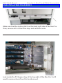
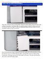
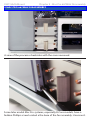
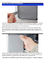
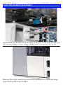
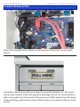
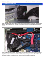
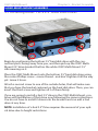
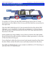
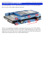
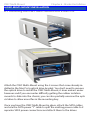
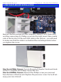
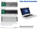
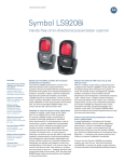
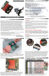
Multi-Mount for Mac Pro
3.5” to 5.25” Drive Bay Converter Bracket
2.5” to 3.5” Drive Bay Converter Bracket
Assembly & Installation
Manual
OWC Multi-Mount
Introduction
1 INTRODUCTION
1.1 System Requirements
1.1.1 Computer Requirements
1.1.2 Hard Drive Requirements
1.1.3 Tool Requirements
1.2 Package Contents
2 MAC PRO 667MHZ DISASSEMBLY
2.1 Mac Pro 667MHz Disassembly
3 MAC PRO 800MHZ DISASSEMBLY
3.1 Mac Pro 800MHz Disassembly
4 CABLE INSTALLATION
4.1 Cable Installation
5 OWC MULTI-MOUNT ASSEMBLY
5.1 Installing either 1 or 2 3.5” Hard Disk Drives
5.2 Installing a 2.5” Hard Disk Drive into the OWC Multi-Mount
5.3 Installing 1 or 2 2.5” Hard Disk Drives
5.4 Installing 1 2.5” Hard Disk Drive and 1 3.5” Hard Disk Drive
6 OWC MULTI-MOUNT INSTALLATION
6.1 Installing the OWC Multi-Mount into a Mac Pro
7 TROUBLESHOOTING & TIPS
7.1 Troubleshooting
7.2 Usage Tips
8 APPENDIX
8.1 FAQ
8.2 About Data Protection
9 CUSTOMER SERVICE
9.1 BEFORE CONTACTING CUSTOMER SERVICE
9.2 CONTACT INFORMATION
IMPORTANT NOTE:
The OWC Multi-Mount drive mounting system brackets are sold
both individually, and also as sets. This manual encompasses both
types of brackets. Please be aware that the item you purchased may
not include all of the items listed here. Please see your invoice for
specific items ordered.
OWC Multi-Mount
Chapter 6 - Bracket Installation
6 OWC MULTI-MOUNT INSTALLATION
Set the optical drive assembly into the optical drive bay, there are 2
screws that line up onto a track in the bottom of the bay. Carefully route
the cabling so that it’s not pinched or disconnected when fitting the carrier into the optical bay.
Fully insert it so that it’s flush into the computer again. The above picture is with 2 optical drives installed; the procedure is identical for 1, 2,
or 3 drives being installed into the optical bay.
OWC Multi-Mount
Introduction
Thank you for purchasing the OWC Multi-Mount system. We’re confident that it will provide years of high-performance service to you.
This guide will get you up and running quickly, demonstrating how
to install your own hard drives into the OWC Multi-Mount bracket
system and into 2 common types of computers.
Should you require additional support after reading this manual
along with the helpful tips and FAQs, please see the inside back
page for OWC customer support options.
Your computer is a static-sensitive device. It is
susceptible to invisible damage if not protected
during installation.
We recommend proper grounding through the use
of a grounding strap. Be sure to work in a clean and
static-free area, and avoid wearing clothing that
retains static charges.
For more information, please visit
http://www.macsales.com/static
Got tools? If you don’t have the tools necessary to complete this in-
stallation, Newer Technology has a fantastic toolkit which includes everything you need to perform this and most other common computer
hardware installations.
It’s available at:
http://www.macsales.com/tools
OWC Multi-Mount
1 INTRODUCTION
Chapter 1 - Introduction
1.1 System Requirements
1.1.1 Computer Requirements
Any 2006 - 2008 Mac Pro system
1.1.2 Hard Drive Requirements
The OWC Multi-Mount is designed to work with any 3.5” or 2.5” mechanical hard disk drive, or SSD drive.
1.1.3 Tool Requirements
• Phillips #1 or #2 Screwdriver
• Needlenose Pliers or Hemostats
1.2 Package Contents
Item
➀ 4 Pin Power to SATA Power Y Cable or single SATA Power Cable*
➁ SATA Straight - Straight Cable*
➂ SATA "L" - Straight Cable* ➃ OWC Multi-Mount 3.5” Drive Bracket (2 pieces)
➄ OWC Multi-Mount 2.5” Drive Bracket (4 pieces, 2 required per drive)*
➅ Screws for 3.5” Bracket - Coarse Thread (16 pieces)*
➆ Screws for 2.5” Bracket - Fine Thread (12 pieces)*
➇ Installation Manual
➀
➃
➁
➄
➂
➅
➇
➆
Multi-Mount for Mac Pro
3.5” to 5.25” Drive Bay Converter Bracket
2.5” to 3.5” Drive Bay Converter Bracket
Assembly & Installation
Manual
*NOTE: Depending on model purchased, contents may differ. Sold as individual units,
and as complete sets. Please check your invoice for proper contents.
OWC Multi-Mount
Chapter 2 - Mac Pro 667MHz Disassembly
2 MAC PRO 667MHZ DISASSEMBLY
2.1 Mac Pro 667MHz Disassembly
Begin by removing the side door on your Mac Pro.
On the lower right, find the memory bay.
OWC Multi-Mount
Chapter 2 - Mac Pro 667MHz Disassembly
2 MAC PRO 667MHZ DISASSEMBLY
Remove the 2 memory riser cards, exposing the 2 Phillips screws shown
here.
Remove the 2 Phillips screws. They are long and extend through the
logic board and into the back of the computer.
OWC Multi-Mount
Chapter 2 - Mac Pro 667MHz Disassembly
2 MAC PRO 667MHZ DISASSEMBLY
At the bottom of the memory bay, there are 2 more Phillips screws. They
are a smaller head than the ones inside the memory bay that you just
removed. Use a Phillips #0 screwdriver to remove the screws.
There is one problem. On many machines, the screws were improperly
installed. Instead of using loctite on the screw standoff, Apple used loctite on the screws themselves, into the standoffs - without loctite on the
standoffs that thread into the Mac Pro’s chassis.
This means, when you try and remove the screws, the standoffs themselves that the screws are screwed into turn. You may need to use a
very thin pair of needlenose pliers, hemostats, or even a thin flat blade
screwdriver to hold the hex-shaped standoff tight, while you loosen the
Phillips screws.
A photo of this task being made look easy, at least if your screws are not
improperly installed as described above. Try and not strip the Phillips
screw heads.
OWC Multi-Mount
Chapter 2 - Mac Pro 667MHz Disassembly
2 MAC PRO 667MHZ DISASSEMBLY
Make sure that the locking latch on the back right side of the Mac Pro.
Then, remove all 4 of the drive bays and set them aside.
Look inside the PCI Express bay at the top right of the Mac Pro. You’ll
need to remove items from this location next.
OWC Multi-Mount
Chapter 2 - Mac Pro 667MHz Disassembly
2 MAC PRO 667MHZ DISASSEMBLY
Using a Phillips P0 screwdriver, loosen the PCI Express cover retaining
plate and remove it. There is a tab at the top that the metal plate latches
into, you’ll need to unscrew the 2 screws and slide the plate down out of
the tab.
Once the metal retaining plate is removed, remove the top PCI Express
dead plate cover from the top slot as shown. Set the dead plate cover
aside, you’ll be using it in a future step.
OWC Multi-Mount
Chapter 2 - Mac Pro 667MHz Disassembly
2 MAC PRO 667MHZ DISASSEMBLY
Remove your PCI Express video card. At the rear of the PCI Express slot,
there is a small plastic tab that you need to lift up to unlock the PCI
Express card. While doing this, pull gently on the card itself toward you
and it will come free. Set the video card aside.
Immediately to the left of the PCI slots, at the top of the logic board, you
will see this Phillips screw. Using a Phillips P0 screwdriver, remove it.
OWC Multi-Mount
Chapter 2 - Mac Pro 667MHz Disassembly
2 MAC PRO 667MHZ DISASSEMBLY
Take the memory bay and gently move it to the right, towards the back
of the computer. You’ll be able to gently shake it and it will pop loose
and move just enough to expose a gap between the processor cover
and the memory bay as shown.
Once the memory bay is moved, you can pull out on the bottom of the
processor cover on the bottom right, and gently remove it from the
computer. It hinges up and to the right as shown. It locks into the fan
shroud on the left fairly tight.
OWC Multi-Mount
Chapter 2 - Mac Pro 667MHz Disassembly
2 MAC PRO 667MHZ DISASSEMBLY
A view of the processor heatsinks with the cover removed.
Some later model Mac Pro systems, especially 8-Core models, have a
hidden Phillips screw located a the base of the fan assembly. Unscrew it.
OWC Multi-Mount
Chapter 2 - Mac Pro 667MHz Disassembly
2 MAC PRO 667MHZ DISASSEMBLY
Take the L shaped PCI card deadplate you removed on page #7. Starting
at the top of the fan shroud, work the short end of the bracket into the
gap at the back of the Mac Pro, as shown above.
Once the bracket is inserted, you can use it as a hook to help pull the
fan assembly out of the Mac Pro. Place the bracket at the bottom left
like shown here. Start putting gentle force on the bracket, pulling on it.
Then....
Using your right hand, wiggle, tug, and pull the entire fan assembly out
of the computer. It attaches to the logic board via a connector that you
don’t need to worry about disconnecting, it’s a pressure fit.
End of Mac Pro 667MHz Install. Please turn to Chapter 4 - Cable Installation
OWC Multi-Mount
Chapter 3 - Mac Pro 800MHz Disassembly
3 MAC PRO 800MHZ DISASSEMBLY
3.1 System Requirements
Begin by removing the side door on your Mac Pro.
Make sure that the locking latch on the back right side of the Mac Pro.
Then, remove all 4 of the drive bays and set them aside.
OWC Multi-Mount
Chapter 3 - Mac Pro 800MHz Disassembly
3 MAC PRO 800MHZ DISASSEMBLY
Immediately to the left of the PCI slots, at the top of the logic board, you
will see this Phillips screw. Using a Phillips P0 screwdriver, remove it.
Remove the cover over the processors by pulling on it. There are magnets securing the cover in place.
OWC Multi-Mount
Chapter 3 - Mac Pro 800MHz Disassembly
3 MAC PRO 800MHZ DISASSEMBLY
Remove the Phillips screw from the base of the fan assembly, located at
the bottom left of the processor heatsinks.
Using your right hand, wiggle, tug, and pull the entire fan assembly out
of the computer. It attaches to the logic board via a connector that you
don’t need to worry about disconnecting, it’s a pressure fit.
OWC Multi-Mount
4 CABLE INSTALLATION
Chapter 4 - Cable Installation
4.1 Cable Installation
Now that you have fully exposed the logic board, look for the 2 SATA
ports, circled here.
Insert the L shaped SATA cable into the top SATA port on the logic
board.
OWC Multi-Mount
4 CABLE INSTALLATION
Chapter 4 - Cable Installation
Insert the straight SATA cable into the bottom SATA port on the logic
board.
Grasp the optical bay with your fingers and pull straight out. The drive
carrier may require a bit of shaking to dislodge it from it’s mounts but it
will come right out. Disconnect the power and ATA cables from the back
of the existing optical drive and set the carrier on a work surface in front
of you.
OWC Multi-Mount
4 CABLE INSTALLATION
Chapter 4 - Cable Installation
Start routing the SATA cables that you have already attached to the logic
board up through the corner of the optical bay, following the existing
wires.
Here you see the proper routing of one of the SATA cables, behind drive
tray #1’s logic board connector. Make very sure you have the cables all
the way tucked in behind the connector before proceeding.
OWC Multi-Mount
5 OWC MULTI-MOUNT ASSEMBLY
Chapter 5 - Bracket Assembly
5.1 Installing either 1 or 2 3.5” Hard Disk Drives
Begin by positioning the bottom 3.5” hard disk drive with the connection ports facing away from you, and then pick up the OWC MultiMount 3.5” drive bracket that has the white OWC Multi-Mount 3.5”
silkscreening on it.
Place the OWC Multi-Mount onto the bottom 3.5” hard disk drive using
the center Phillips screw - coarse thread - and don’t tighten it all the way
yet. Leave it loose.
Attach a second screw to one of the outside holes, that will make sure
that you have the bracket centered on the hard disk drive. Then, you can
insert the third screw and tighten all 3 of them firmly.
If you are going to install a 2nd 3.5” drive in the OWC Multi-Mount, continue with installation of that drive now following the same instructions.
You do not have to install 2 drives into the bracket and can add a 2nd
drive at any time.
NOTE: Installation of a 2nd 3.5” Drive requires the removal of your optical drive due to height restrictions.
OWC Multi-Mount
5 OWC MULTI-MOUNT ASSEMBLY
Chapter 5 - Bracket Assembly
Once you have the right bracket installed, rotate the hard drive and attach the left side bracket using the same method as step 1.
You also can add a 2.5” hard disk drive using the OWC 2.5” Multi-Mount.
See the next chapter if you are wanting to install a mixed environment
of drive mechanisms.
The OWC 3.5” Multi-Mount assembly is ready to install into your system.
OWC Multi-Mount
Chapter 5 - Bracket Assembly
5 OWC MULTI-MOUNT ASSEMBLY
5.2 Installing a 2.5” Hard Disk Drive
To install a 2.5” Drive into the OWC Multi-Mount, place the 2.5” drive
mechanism on the table in front of you, with the interface connection to
the right side.
Take the OWC Multi-Mount 2.5” drive bracket that has the white OWC
silkscreen on it, and attach it to the drive mechanism as shown above,
with the portion of the bracket that has the OWC logo extended off of
the drive to the left.
Firmly tighten the large Phillips screws that are held to the OWC MultiMount bracket through vibration isolation rubber grommets to the side
of the hard drive facing you.
Once attached, rotate the drive around and repeat using the other drive
bracket. Make certain that all screws are firmly inserted into the drive.
The OWC 2.5” Multi-Mount is now ready to install into a 3.5” drive bay, or
into the OWC 3.5” Multi-Mount.
OWC Multi-Mount
Chapter 5 - Bracket Assembly
5 OWC MULTI-MOUNT ASSEMBLY
5.3 Installing 1 or 2 2.5” Hard Disk Drives
Once you have the 2.5” OWC Multi-mount attached to the 2.5” hard disk
drive, you can install up to (2) 2.5” drives onto the 3.5” OWC Multi-Mount
bracket.
In the above picture you see an arrow pointing towards the extended
portion of the 2.5” OWC Multi-Mount bracket. That would be the front of
the drive, the 2.5” OWC Multi-Mount bracket says “OWC” silkscreened in
white right on that portion of the bracket. You need to place the bracket
in this orientation to properly install.
The 3.5” OWC Multi-Mount bracket that you are attaching the 2.5” OWC
Multi-Mount bracket to has the white OWC text silkscreening on it as
well. Use that as your orientation.
The picture on the next page may also assist in orientation.
OWC Multi-Mount
5 OWC MULTI-MOUNT ASSEMBLY
Chapter 5 - Bracket Assembly
Here you see a completed assembly comprised of one set of 3.5” OWC
Multi-Mount drive brackets, and two sets of 2.5” OWC Multi-Mounts, all
assembled into one unit.
The 2.5” OWC Multi-Mount is attached to the 3.5” OWC Multi-Mount using 6 of the fine thread Phillips screws included with the mount - 3 per
side, 6 total per drive bracket assembly. It’s easiest to start the center
screw, but not fully tighten it, and then insert the outer two screws. This
assures that you have the bracket lined up perfectly before continuing.
OWC Multi-Mount
Chapter 5 - Bracket Assembly
5 OWC MULTI-MOUNT ASSEMBLY
5.4 Installing 1 2.5” Hard Disk Drive and 1 3.5” Hard Disk
Drive into the OWC Multi-Mount
This is a completed assembly comprised of one set of 3.5” OWC MultiMount drive brackets, and one set of 2.5” OWC Multi-Mount, all assembled into one unit. Be sure to orient the bracket so that the SATA ports
both point towards the rear of the Multi-Mount.
OWC Multi-Mount
Chapter 6 - Bracket Installation
6 OWC MULTI-MOUNT INSTALLATION
6.1 Installing the OWC Multi-Mount into a Mac Pro
Attach the OWC Multi-Mount using the 4 screws that come already installed in the Mac Pro’s optical drive bracket. You don’t need to remove
the optical drive to install the OWC Multi-Mount, it does make it easier
however and if you encounter difficulty getting the rubber isolation
mounts to slide into the chassis, you can also partially unscrew the optical drive to allow more flex in the mounting bay.
Once you have the OWC Multi-Mount in place, attach the SATA cables
and use the SATA power “Y” cable to split the existing power cable to 2
separate SATA power connections and attach them to the drives.
OWC Multi-Mount
Chapter 6 - Bracket Installation
6 OWC MULTI-MOUNT INSTALLATION
Reinsert the fan module into the computer, sliding it on it’s base track
and then reinserting it’s Phillips screw into the logic board. Take careful
note of the location of the red SATA cable in this picture - you will need
to make sure that the cable is not behind the mounting bracket when
you tighten the screw.
Mac Pro 667MHz Owners; Turn to the end of Chapter 2 and work backwards to complete reassembly of your Mac Pro.
Mac Pro 800MHz Owners: Reinsert the Phillips screw you removed
from the base of the fan unit. Replace the processor cover. You’re all set enjoy your new drive(s)!
OWC Multi-Mount
7 TROUBLESHOOTING & TIPS
Chapter 7 - Troubleshooting & Tips
7.1 Troubleshooting
Having problems installing? Go back and examine the steps and photographs. Most fit issues can be traced to missing a step or a screw.
Double check that your brackets are facing the correct direction and
that you are not orienting the drive backwards. You want to be sure that
the SATA ports are pointing in the right direction for your case installation.
7.2 Usage Tips
Once you have installed your drives into the OWC Multi-Mount bracket
system, route your cables using the shortest path possible, but definitely use any holes or grommets that your case has to offer. Don’t pinch
any cables and make certain to not route your wires over sharp edges or
corners.
OWC Multi-Mount
8 APPENDIX
Chapter 8 - Appendix
8.1 FAQ
Q: How do I format my storage solution?
A: OWC has detailed instructions online for most popular operating
systems, located at: http://eshop.macsales.com/tech_center/fwhdd.cfm
Q: What file system should I choose when formatting my drive?
A: This will depend on how you want to use the drive, but in general we
recommend:
• Mac OS X : HFS + (Mac OS Extended)
• Windows 2000/XP/Vista/7 : NTFS
• For cross-platform compatibility, FAT32 will work, but single file sizes
are limited to 4GB. Other options using 3rd party software exist but are
not covered here.
Q: Will the hard drives spin down when my computer goes to sleep or
into stand-by mode?
A: Yes, they will spin down to save energy. It will take about 30 seconds
to access your data after being in sleep or stand-by mode.
8.2 About Data Protection
To ensure that your files are protected and to prevent the loss of your
data, we strongly suggest that you keep two copies of your data: one
copy on you primary hard drive, and a second copy on either your secondary internal hard drive or another storage medium, such as an optical backup, or on a second external hard drive. Any data loss or corruption while using the OWC Multi-Mount is the sole responsibility of the
user, and under no circumstances will Other World Computing be held
liable for compensation or the recovery of any lost data.
OWC Multi-Mount
9 CUSTOMER SERVICE
Chapter 9 - Customer Service
9.1 Before Contacting Customer Service
•Read this manual and review Chapter 4: Troubleshooting & Tips.
•Try to confirm the problem is with the hard drive. If you have a second
computer, move the enclosure to that system and verify that the solution does not function with that machine.
•Visit our tech center for more support suggestions, including FAQs.
http://eshop.macsales.com/tech_center/index.cfm
If you still need support, please have the following available to you:
• The serial number of the enclosure
• Your invoice number
• What operating system you are using
• Which kind and model of computer you are using
All of this will help speed your support contact along.
9.2 Support Hours Of Operation
8AM - 10PM CT Monday - Friday
9AM - 4PM CT Saturday
By Telephone - (800) 275-4576 (North America only)
International customers please call (815) 338-8685
Live Chat is available 24 hours a day, 7 days a week . Visit:
http://eshop.macsales.com for more information.
Or, you can email. Submit your email at
http://eshop.macsales.com/Service/Tech.cfm
Copyrights:
Copyright © 2010 Other World Computing, Inc. All rights reserved. OWC is a registered trademark of Other World Computing. Other World Computing and Mercury Elite-AL Pro are trademarks of Other World Computing. Other marks may be the
trademark or registered trademark property of their respective owners.
No part of this publication may be reproduced, stored in a retrieval system, or transmitted in any form or by any means,
electronic, mechanical, photocopying, recording or otherwise, without the prior written consent of Other World Computing.
Changes:
The material in this document is for information only and subject to change without notice. While reasonable efforts have
been made in the preparation of this document to assure its accuracy, Other World Computing assumes no liability resulting
from errors or omissions in this document, or from the use of the information contained herein. Other World Computing reserves the right to make changes or revisions in the product design or the product manual without reservation and without
obligation to notify any person of such revisions and changes.
FCC Statement:
Warning! Modifications not authorized by the manufacturer may void the user’s authority to operate this device.
NOTE: This equipment has been tested and found to comply with the limits for a Class A digital device, pursuant to Part 15
of the FCC Rules. These limits are designed to provide reasonable protection against harmful interference when the equipment is operated in a commercial environment. This equipment generates, uses, and can radiate radio frequency energy
and, if not installed and used in accordance with the instruction manual, may cause harmful interference with radio communications. Operation of this equipment in a residential area is likely to cause harmful interference, in which case the user will
be required to correct the interference at his own expense.
NOTE: This equipment has been tested and found to comply with the limits for a Class B digital device, pursuant to Part 15
of the FCC Rules. These limits are designed to provide reasonable protection against harmful interference in a residential
installation. This equipment generates, uses and can radiate radio frequency energy and, if not installed and used in accordance with the instructions, may cause harmful interference to radio communications. However, there is no guarantee
that interference will not occur in a particular installation. If this equipment does cause harmful interference with radio or
television reception, which can be determined by turning the equipment off and on, the user is encouraged to try to correct
the interference by one or more of the following measures:
• Reorient or relocate the receiving antenna.
• Increase the separation between the equipment and receiver.
• Connect the equipment to an outlet on a circuit different from that to which the receiver is connected.
Health And Safety Precautions:
• Use proper anti-static precautions while performing the installation of your hard drives into this drive enclosure. Failure to
do so can cause damage to your drive mechanisms, and / or the hard drive enclosure.
• Read this User’s Guide carefully, and follow the correct procedure when setting up the device.
• Do not open your hard drive or attempt to disassemble or modify it. Never insert any metallic object into the drive to avoid
any risk of electrical shock, fire, short-circuiting or dangerous emissions. Your hard drive contains no user-serviceable parts.
If it appears to be malfunctioning, have it inspected by a qualified Other World Computing Technical Support representative.
• Never expose your device to rain, or use it near water, or in damp or wet conditions. Never place objects containing liquids
on the drive, as they may spill into its openings. Doing so increases the risk of electrical shock, short-circuiting, fire or
personal injury.
General Use Precautions:
• Do not expose the enclosure to temperatures outside the range of 5° C to 40° C (41° F to 104° F). Doing so may damage
the drive or disfigure its casing. Avoid placing your drive near a source of heat or exposing it to sunlight (even through a
window). Conversely, placing your drive in an environment that is too cold or humid may damage the unit.
• Always unplug the hard drive from the electrical outlet if there is a risk of lightning or if it will be unused for an extended
period of time. Otherwise, there is an increased risk of electrical shock, short-circuiting or fire.
• Use only the power supply shipped with the device.
• Do not use the hard drive near other electrical appliances such as televisions, radios or speakers. Doing so may cause
interference which will adversely affect the operation of the other products.
• Do not place the drive near sources of magnetic interference, such as computer displays, televisions or speakers. Magnetic
interference can affect the operation and stability of your hard drive.
• Do not place heavy objects on top of the drive.
• If you detect a problem, consult the Troubleshooting section in this manual.
• Protect your hard drive from excessive exposure to dust during use or storage. Dust can build up inside the device, increasing the risk of damage or malfunction.
• Other World Computing recommends the use of normal glass cleaning products to keep the high lustre finish at its finest
with this product. Be sure not to get any moisture inside the holes and if you do, allow time to air dry before use.
• Do not block the ventilation outlets on the front of the drive. These help to keep your drive cool during operation. Blocking the ventilation outlets may cause damage to your drive and cause an increased risk of short-circuiting or fire.
R1 6/30/10 JD
OWCMANMULTIMP
Copyright ®2010 Other World Computing All Rights Reserved. Other World Computing’s Limited Warranty is not transferable and subject to limitations.