1
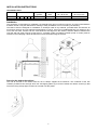
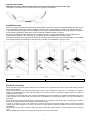
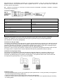
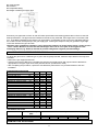
OPERATION AND MAINTENANCE MANUAL
RONDO’ gas cooker hobs
cod. 7052 142, 7052 642
Foster spa - via M.S. Ottone, 18/20 - 42041 Brescello (RE) Italy - www.fosterspa.com
tel. +39.0522.687425 - tel. Servizio Assistenza +39.0522.684450
fax +39.0522.686019 - fax Servizio Ricambi +39.0522.962166 e-mail: [email protected]
INSTALLATION INSTRUCTIONS
TECHNICAL DATA
MODELS
Burners
A
1
SR
1
R
1
TC
-
-
Automatic
ignition
Safety
valve
Product dimensions
(W x D) in mm
Cut-out dimensions
(W x D) in mm
yes
yes
Ø 520
Ø 500
Installation
The purchaser is responsible for installation: the Manufacturer does not offer this service. Any technical assistance
activities carried out by the Manufacturer relating to faulty installation are not covered by the warranty.
The built-in hobs are designed for installation on worktops made of any material, provided these are between 25
mm and 40 mm thick and can withstand temperatures of 100°C. If the hob is installed adjacent to a cabinet on any
one of the two sides, at least 150 mm must divide the hob edge from the cabinet, while the distance between the
rear wall and hob edge must be at least 50 mm. A partition made of insulating material (wood or similar) must be
inserted in the underlying cabinet at least 20 mm from the bottom edge of the hob.
Securing the hob to the cabinet
The hob is secured to the cabinet with the aid of clamps supplied as accessories. The underside of the hob
contains pre-drilled holes through which the self-tapping plates (A) must be inserted; the relative screws (C) that
secure the fixing clamps (B) must then be screwed onto the plates.
8
Applying the sealant
Important - the picture below indicates how the sealant must be applied along the entire edge.
This appliance is designed for non-professional use in domestic environments.
Installation room
The use of a gas cooker hob generates heat and humidity in the room in which it is installed. Make sure the room is
well ventilated by keeping any natural ventilation openings open or by installing a cooker hood with flue duct (Fig.
1-2). Intensive and prolonged use of the appliance may require additional ventilation, either by opening a window or
by increasing the efficiency and power of the mechanical ventilation system, if present.
An electric ventilator must be implemented if a cooker hood (Fig. 2) cannot be installed: it must be fitted to the
external wall or window in the room (Fig. 3), provided the room is equipped with air intake vents.
The electric ventilator must guarantee an hourly air exchange rate 3-5 times the volume of the kitchen. The installer
must comply with the specifications of the UNI-CIG 7129 and 7131 standards currently in force.
Fig. 1
Fig. 2
min.
Fig. 3
min.
Electrical connection
Check the data on the rating plate located on the underside of the appliance and verify that the rated voltage complies
with the mains voltage.
Check the efficiency of the earthing system before carrying out the electrical connection. It is mandatory to earth the
appliance. The Manufacturer shall not be held liable for any harm to persons or damage to objects arising from failure to
comply with this provision.
If the model is not equipped with a plug, install a standardised plug on the cable that is capable of withstanding the power
output indicated on the rating plate. The earth wire is identified by the yellow-green jacket. The plug must always be
accessible.
When carrying out a fixed connection to the mains electricity, an omnipolar cut-off device with a contact gap of at least 3
mm must be installed between the appliance and the power outlet.
In order to connect the cord to the cooker hob, loosen and remove the terminal board cover to access the contacts
located inside. After making the connection, secure the cord with the fixing system provided and cover the terminal board
immediately.
Whenever the power cord is replaced, make sure that the earth wire (yellow-green) is 10 mm longer than the remaining
wires.
Use an H05RR-F type rubber cord comprising wires with 3x1.5 mm cross-section.
9
DECLARATION OF CONFORMITY. Regarding the components intended to come into contact with foodstuffs, this
appliance conforms to the specifications of Italian Legislative Decree no. 108 dated 25/01/1992 which implements
European Directive 89/109/EEC.
CE - Appliance manufactured in conformity to European Directives 90/396/EEC, 89/336/EEC, 93/68/EEC, 73/23/EEC
and subsequent amendments.
Connection options
RETE DI ALIMENTAZIONE ELETTRICA
MAINS ELECTRICITY
LINEA
LIVE
TERRA
EARTH
NEUTRO
NEUTRAL
MARRONE
BROWN
GIALLO/VERDE
YELLOW/GREEN
BLU
BLUE
CAVO DI ALIMENTAZIONE
POWER CORD
GAS CONNECTION
Appropriate rating plates on the gas cooker hob indicate the type of gas for which the hob is configured.
However, the appliance can be operated with other types of gas after carrying out simple adjustments.
(See indications in the following paragraphs)
Connection to the gas supply
Connection of the appliance to the gas piping or cylinder must be carried out in conformity to the UNI-CIG7129 and
7131 standards, after verifying that the hob is suitably configured for the intended type of gas. If not, carry out the
operations indicated in the paragraph <<Adjustment for different types of gas>>. In the event of liquid gas supply
(from a cylinder), use pressure valves that conform to UNI-CIG 7432 specifications.
Important: in order to ensure safe operation, optimal energy consumption and appliance durability, make sure that
the supply pressure complies with the values indicated in the "Burner specifications" table (on page 5)
Installation of the gas pipe fitting
The instructions are intended for personnel authorised to install the appliance in conformity to UNI-CIG 7131
specifications. All operations must be carried out while the appliance is disconnected from the power supply.
CAUTION: two different fittings are included in the packaging - one cylindrical and the other conical. Select the
most appropriate type depending on the country of installation.
CYLINDRICAL
CONICAL
Installation steps:
▪ Screw the adjustable fitting onto the gas rail feed pipe (with cylindrical size ½ male gas thread) on the appliance
(A1) with the appropriate sealing gasket (A2).
▪ Tighten the fitting thoroughly while making sure it lies in the right direction.
▪ Connect the cooker hob to the gas supply line by screwing the supply pipe to the adjustable fitting and inserting
the sealing gasket.
10
A1 =Gas rail pipe
A2 =Gasket
A3 =Adjustable fitting
A4 =Rigid or flexible gas supply pipe
Exclusively use pipes that conform to UNI-CIG 9891 specifications and sealing gaskets that conform to UNI-CIG
9264 specifications. The pipes must be installed so that when fully extended, their length does not exceed 2,000
mm. To facilitate installation and avoid the risk of gas leaks, it is advisable to first connect the adjustable fitting to
the cooker hob then subsequently to the gas supply pipe. Inverting this sequence may not guarantee a gas-tight
connection between the pipe and hob.
Important: after completing installation, verify the perfect tightness of all the fittings using a soapy solution
- never a flame. Moreover, ensure that the flexible pipe does not lie in the path of moving parts in the
underlying cabinet (e.g. drawers) and that its position safeguards it against possible damage.
ADJUSTMENT FOR DIFFERENT TYPES OF GAS
To adjust the gas hob for a different type of gas to that originally intended, follow the steps below in the sequence
indicated:
▪ Remove the pan support and burner.
▪ Unscrew the injectors ( M ) using a suitable plug spanner and replace them with injectors whose diameter is
appropriate for the type of gas to be used (see the “Burner specifications” table).
▪ After completing the procedure, replace the old calibration plate with the one provided relative to the new
installation.
BURNER SPECIFICATIONS
Burners
Rated heat input
Reduced heat input
minimum heat input DE-AT
Ø INJECTOR:
G30/G31 28..30/30-37 mbar
G30/G31 50 mbar
G20 20 mbar
G25 25 mbar
G25 20 mbar
G110 8 mbar
G120 8 mbar
Ø BY-PASS:
G30/G31 28..30/30-37 mbar
G30/G31 50 mbar
G20 20 mbar
G25 25 mbar
G25 20 mbar
G110 8 mbar
G120 8 mbar
kW
kW
kW
A
1
0.45
0.55
SR
1.75
0.70
0.90
R
3.00
1.00
1.30
mm
mm
mm
mm
mm
mm
mm
0.50
0.43
0.72
0.72
0.77
1.45
1.40
0.65
0.58
0.97
0.94
1.00
1.85
1.80
0.85
0.75
1.15
1.21
1.34
2.60
2.40
mm
mm
mm
mm
mm
mm
mm
0.28
0.28
Adj.
Adj.
Adj.
Adj.
Adj.
0.31
0.31
Adj.
Adj.
Adj.
Adj.
Adj.
0.42
0.42
Adj.
Adj.
Adj.
Adj.
Adj.
HOB SPECIFICATIONS
Model
Total power output
(kW)
7052 - 142/642
5.75
Consumption
G30 g/h
601
G20 m³/h
0.78
MINIMUM FLOW ADJUSTMENT
11
G25 m³/h
0.91
G110 m³/h
1.87
G120 m³/h
1.67
Switch the burner on, set the valve to the minimum position then remove the knob (it is pressure-fitted thus easily
removable).
Use a small screwdriver to turn the valve adjustment screw - anti-clockwise to increase the gas flow and clockwise
to reduce the gas flow - until the flame is 3-4 mm long.
For LPG (in cylinder), turn the by-pass clockwise until it reaches the end.
COOKER HOB OPERATION
Instructions for the user
This appliance is designed for domestic cooking purposes and must be operated for its intended use only. Any
other use of the appliance constitutes improper use and is dangerous.
The manufacturer shall not be held liable for any damages resulting from improper, incorrect or unreasonable use.
Operating the burners
If the burners have not been used for several days, wait a few seconds before igniting them to enable the air in the
piping to escape.
The burners are equipped with an automatic ignition device and can be ignited by simply turning the knob towards
the small star symbol. The ignition generator is of the repetitive discharge type.
If the flame does not ignite within 5 seconds, turn the knob back to position 0 and repeat the operation.
On models equipped with a flame safety device (that interrupts the flow of gas should the flame accidentally
extinguish), the burners can be ignited in the above-mentioned manner, provided the knob is kept fully
depressed for roughly 5-6 seconds after the flame ignites.
After this time - which is necessary to engage the safety device - the flame burns permanently.
CAUTION: after cleaning the hob, make sure that the burner is properly inserted in its housing and does
not interfere with the spark plug.
For more efficient use of the burners, we recommend using flat-bottomed pots with suitable diameter in relation to
the chosen burner.
When using small-diameter cookware (coffee pots, tea pots, etc.), adjust the burner power so that the flame does
not spread over the edges of the cookware. Do not use cookware with concave or convex bottom.
WARNING: should the burner flame accidentally extinguish, shut off the control knob and attempt to
reignite the burner after at least 1 minute.
CLEANING AND MAINTENANCE
Prior to carrying out any maintenance on the hob, unplug the appliance or disconnect it from the power supply by shutting
off the mains switch.
Wait for the appliance to cool down before effecting cleaning operations; wash any enamelled, painted or chrome-plated
parts with the aid of warm water and soap or a non-corrosive liquid detergent.
Steel parts can be cleaned with methylated spirits or other specific products available on the market. Use cotton or a
cloth wetted with vaseline or seed oil to clean aluminium profiles and panels. Clean then wipe using methylated spirits.
Never use abrasive or corrosive detergents, bleach or acids for cleaning operations.
Avoid leaving acidic or alkaline residues (lemon juice, vinegar, etc.) on enamelled, painted or stainless steel parts.
TECHNICAL ASSISTANCE
Verify the following before contacting the Technical Assistance Service:
In the event of cooker hob malfunctions, we recommend verifying that the plug is properly inserted in the power socket
and that the gas flows normally to the hob.
Should you fail to identify the cause of the malfunction:
switch off the appliance, do not tamper with it and contact the Technical Assistance Service.
The appliance comes with a warranty certificate that enables the owner to benefit from the Technical Assistance
Service.
The warranty certificate must be stored and duly filled in to be presented to the Technical Assistance Service whenever
required, together with a fiscally valid document issued by the dealer at the moment of purchase (delivery note, invoice,
tax receipt, other) and indicating the dealer's name, delivery date, product identification data and purchase price.
12