Transcript
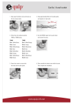
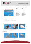
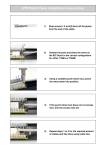
Artikel
Articles
Montageanleitung für Cat.6 Patch Panel 8-12 Port
Pair
0
Abdeckung demontieren
Open the aluminum cover.
3
T568A
Pin 5
Pin 4
Pin 1
Pin 2
Pin 3
Pin 6
Pin 7
Pin 8
White/Blue
Blue
White/Green
Green
White/Orange
Orange
White/Brown
Brown
Kabelmantel abisolieren,
Geflechtschirm umschlagen
Strip cable jacket,
fold back braid shield
T568B
Pin 5
Pin 4
Pin 1
Pin 2
Pin 3
Pin 6
Pin 7
Pin 8
10
Unit: mm
n
p
o w r.
n
pr
.
36
12
20
20
30
27
br
ee
54
bl
2
gr
1
r.
Full shielded patch panel installation instruction
ue
o r p r.
an
ge
p
68882
93047
96105
93041
69306
69307
78
40
35
T 568B
50
60
44
Paarfolien vorbereiten
Prepare pair foils
4
White/Blue
Blue
White/Green
Orange
White/Green
Green
White/Brown
Brown
Farbcode wählen und Adernpaare in die LSA-Kontakte legen
Follow the direction on the color-coding sticker to
position T568A or T568B wiring,separate a little space on
proper position and insert the wire pair by pair into each slot.
Adernpaare mit Einlegewerkzeug auflegen
Paarfolie erst ca. 2mm vor der LSA Leiste Kürzen!
Install twisted pairs with LSA tool
Cut pairfoils not more than ca.2mm to LSA terminal!
5
Kabelschirm unter die Klemmen legen und handfest anziehen
Fasten the screws through metal case to hold
tightly down for two cable jackets in the same time.
6
Installierte Kabel mit Kabelbindern zugentlasten
Use cable ties for strain relief
Revisionsdatum
Revision Date
Version 1
2014-01-29