1
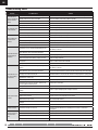
® Carbon-Z Cub Instruction Manual Bedienungsanleitung Manuel d’utilisation Manuale di Istruzioni IMAA Legal EN NOTICE All instructions, warranties and other collateral documents are subject to change at the sole discretion of Horizon Hobby, Inc. For up-to-date product literature, visit www.horizonhobby.com and click on the support tab for this product. Meaning of Special Language: The following terms are used throughout the product literature to indicate various levels of potential harm when operating this product: NOTICE: Procedures, which if not properly followed, create a possibility of physical property damage AND little or no possibility of injury. CAUTION: Procedures, which if not properly followed, create the probability of physical property damage AND a possibility of serious injury. WARNING: Procedures, which if not properly followed, create the probability of property damage, collateral damage, and serious injury OR create a high probability of superficial injury. WARNING: Read the ENTIRE instruction manual to become familiar with the features of the product before operating. Failure to operate the product correctly can result in damage to the product, personal property and cause serious injury. This is a sophisticated hobby product. It must be operated with caution and common sense and requires some basic mechanical ability. Failure to operate this Product in a safe and responsible manner could result in injury or damage to the product or other property. This product is not intended for use by children without direct adult supervision. Do not use with incompatible components or alter this product in any way outside of the instructions provided by Horizon Hobby, Inc. This manual contains instructions for safety, operation and maintenance. It is essential to read and follow all the instructions and warnings in the manual, prior to assembly, setup or use, in order to operate correctly and avoid damage or serious injury. Age Recommendation: Not for children under 14 years. This is not a toy. Safety Precautions and Warnings As the user of this product, you are solely responsible for operating in a manner that does not endanger yourself and others or result in damage to the product or the property of others. • Always keep a safe distance in all directions around your airplanes to avoid collisions or injury. This airplanes is controlled by a radio signal subject to interference from many sources outside your control. Interference can cause momentary loss of control • Always operate your airplanes in open spaces away from full-size vehicles, traffic and people. • Always carefully follow the directions and warnings for this and any optional support equipment (chargers, rechargeable battery packs, etc.). • Always keep all chemicals, small parts and anything electrical out of the reach of children. • Always avoid water exposure to all equipment not specifically designed and protected for this purpose. Moisture causes damage to electronics. • Never place any portion of the airplanes in your mouth as it could cause serious injury or even death. • Never operate your airplanes with low transmitter batteries. • Always keep aircraft in sight and under control. • Always use fully charged batteries. • Always keep transmitter powered on while aircraft is powered. • Always remove batteries before disassembly. • Always keep moving parts clean. • Always keep parts dry. • Always let parts cool after use before touching. • Always remove batteries after use. • Always ensure failsafe is properly set before flying. • Never operate aircraft with damaged wiring. • Never touch moving parts. To register your product online, visit www.e-fliterc.com 2 ® EN The E-flite Carbon-Z Cub ® ® hank you for purchasing the E-flite Carbon-Z Cub aircraft. Like the full-scale Carbon Cub SS airplane available from Cub Crafters, in your hands is a remarkTCarbon-Z ably versatile airplane designed by World Aerobatic Champion, Quique Somenzini, to deliver a pleasure cruiser with incredible muscle. In conjunction with rigid construction, the remarkable AS3X system built into the included Spektrum AR635 receiver (BNF Basic version only) makes it possible for you to ® ™ experience a performance envelope that’s wider than ever before possible, more stable and crisp on the controls. This means that no matter how you like to fly, you’ll enjoy both rock-solid stability and maneuverability without any sacrifice in precision or control feel. Although this aircraft may look tame, its brushless power system has been specially chosen to offer brutish performance for unbelievable STOL performance as well as unexpected 3D aerobatic agility. In addition, its ready to become your favorite tow plane for sailplanes and can easily carry a camera above the cabin making this already amazing model the ultimate utility aircraft. Plus, you can make your Carbon-Z Cub even more versatile by adding the optional Carbon-Z Cub Float Set to the hard points already built into the airframe that allow you to make virtually any place in the world a viable flying site. Your Carbon-Z Cub aircraft represents the benchmark of performance and aerobatic versatility. And it’s brought to you at both the high-value Bind-N-Fly® Basic and Plug-N-Play® completion levels. All you have to do next is read and apply the information presented in this instruction manual. Box Contents Specifications Table of Contents BL50 Brushless Outrunner Motor, 525Kv 60-Amp Pro Switch-Mode BEC Brushless ESC (V2) (4) 26 g Digital MG Mini Servo (EFLR7145) (2) 13 g Digital MG Micro Servo (EFLR7155) Spektrum™ AR635, 6-Channel AS3X® Sport Receiver Included Included Installed Installed Installed Installed Installed Required to Complete Battery: 3200mAh 22.2V 6S 30C Required to Required to Li-Po (EFLB32006S30) Complete Complete Battery Charger: 6-cell Li-Po battery balancing charger Required to Required to Complete Complete Recommended Transmitter: Full-Range 6 channel 2.4GHz with Spektrum DSM2®/DSMX® technology with programmable Mixing. Required to Required to Complete Complete 55.8 in (1419mm) 84.6 in (2150mm) 8.15 lb (3.7 kg) 1100 in² (71 dm²) AS3X System .......................................................................................4 Receiver Selection and Installation .......................................................4 Transmitter and Receiver Binding.........................................................5 Battery Installation ...............................................................................6 Low Voltage Cutoff (LVC) ......................................................................6 Arming the ESC and Receiver...............................................................7 Landing Gear Installation .....................................................................8 Rudder Installation ...............................................................................9 Horizontal Tail Installation ..................................................................10 Motor and Propeller Installation .........................................................11 Wing Installation ................................................................................12 Center of Gravity (CG) .......................................................................14 Control Direction Test .........................................................................14 Control Horn and Servo Arm Settings .................................................14 Control Surface Centering ..................................................................15 AS3X Control Direction Test ..............................................................15 Transmitter Setup .............................................................................16 Dual Rates, Expos and Mixing ............................................................16 Preflight Preparation ..........................................................................16 Flying Tips and Repairs ......................................................................17 Post Flight Maintenance .....................................................................18 Optional Tow Release Installation .......................................................18 Optional Camera Mount Installation....................................................19 AMA National Model Aircraft Safety Code ...........................................20 Troubleshooting Guide AS3X .............................................................21 Troubleshooting Guide .......................................................................22 Limited Warranty ...............................................................................23 Contact Information ...........................................................................24 FCC Information .................................................................................24 Compliance Information for the European Union .................................24 Replacement Parts.............................................................................90 Optional Parts ....................................................................................91 3 EN AS3X System Horizon Hobby has always made RC sport, scale and unique aircraft with the kind of performance experts appreciate. First used in Blade® ultra micro flybarless helicopters, MEMS sensor technology within the Artificial Stability--3 axis (AS3X) System has been specifically tuned for airplanes helping invisibly correct for turbulence, torque and tip stalls. The outstanding control agility delivers an ultra smooth, locked-in feel that obeys your every command with performance that’s natural feeling. It’s so gratifying, in fact, that it’s as though you’re the RC pilot of an expertly tuned, giant-scale aircraft. Welcome to AS3X, your parkflyer will never be the same! To see what we mean, go to www.E-fliteRC.com/AS3X. Now the exclusive AS3X Stabilization system makes the leap from Ultra Micro aircraft to high performance parkflyers with the AR635 receiver. The precision and performance available from AS3X equipped Ultra Micro airplanes has heralded a new era of performance, and with the AR635, that performance is introduced for larger airplanes. Receiver Selection and Installation The Spektrum AR635 receiver is recommended for ths airplane. If you choose to install another receiver, ensure that is at least a 6-channel full range (sport) receiver. Refer to your receiver manual for correct installation and operation instructions. Installation (AR635 shown) 1. Remove the screw (A) and radio hatch (B) from the top of the fuselage. 2. Install your full range (sport) receiver in the fuselage using double-sided servo tape. B 3. Attach the elevator and rudder servo connectors to the appropriate channels of the receiver. A 4. Attach the aileron Y-harness to the aileron channel of the receiver. 5. Attach the Flaps Y-harness to the AUX1. 6. Attach the ESC connector to the throttle channel of the receiver. 4 ® EN Transmitter and Receiver Binding WARNING AGAINST COUNTERFEIT PRODUCTS: If you ever need to replace your Spektrum receiver found in a Horizon Hobby product, always purchase from Horizon Hobby, Inc. or a Horizon Hobby authorized dealer to ensure authentic high-quality Spektrum product. Horizon Hobby, Inc. disclaims all support and warranty with regards, but not limited to, compatibility and performance of counterfeit products or products claiming compatibility with DSM or Spektrum. Binding is the process of programming the receiver to recognize the GUID (Globally Unique Identifier) code of a single specific transmitter. You need to ‘bind’ your chosen Spektrum™ DSM2®/DSMX® technology equipped aircraft transmitter to the receiver for proper operation. Please visit www.bindnfly.com for a complete list of compatible transmitters. CAUTION: When using a Futaba® transmitter with a Spektrum DSM module, you must reverse the throttle channel and rebind. Refer to your Spektrum module manual for binding and failsafe instructions. Refer to your Futaba transmitter manual for instructions on reversing the throttle channel. Read the transmitter instructions for binding to a receiver (location of transmitter’s Bind control). 1. Make sure the transmitter is powered off. 2. Move the transmitter controls to neutral (flight controls: rudder, elevators and ailerons) or to low positions (throttle, throttle trim).** 3. Install a bind plug in the receiver bind port. 4. Connect the flight battery to the ESC, then power on the ESC switch. The ESC will produce a series of sounds. One long tone, then 6 short tones confirm that the LVC is set correctly for the ESC. The orange bind LED on the receiver will begin to flash rapidly. 5. Power on the transmitter while holding the transmitter bind button or switch. Refer to your transmitter’s manual for binding button or switch instructions. 6. When the receiver binds to the transmitter, the orange bind light on the receiver will turn solid and the ESC will produce a series of three ascending tones. The tones indicate the ESC is armed, provided the throttle stick and throttle trim are low enough to trigger arming. 7. After binding, the 3 LEDs (blue, yellow and red) on the receiver will flash. The flashing indicates the gain setting for each axis. The quicker the flash, the higher the gain setting. For more information, refer to the “Initializing the AR635” section in the receiver manual. 8. Remove the bind plug from the bind port. 9. Safely store the bind plug (some owners attach the bind plug to their transmitter using two-part loops and clips). Bind Plug Installation ** The throttle will not arm if the transmitter’s throttle control is not put at the lowest position. If you encounter problems, follow the binding instructions and refer to the transmitter Troubleshooting Guide for other instructions. If needed, contact the appropriate Horizon Product Support office. 10. The receiver should retain the binding instructions received from the transmitter until another binding is done. 5 EN Battery Installation Battery Selection • We recommend the E-flite 3200mAh 22.2V 6S Li-Po battery (EFLB32006S30). Refer to the Optional Parts List for other E-flite batteries. If using a battery other than those listed, the battery should be within the range of capacity, dimensions and weight of the E-flite Li-Po battery packs to fit in the fuselage without changing the center of gravity a large amount. A 1. Press the latch button (A) to lift the rear edge of the canopy hatch, then pull the hatch up and back from the fuselage. 2. Apply the included strip of hook and loop tape to the bottom of your battery(s). 3. For the recommended CG, install the battery(s) in the middle of the compartment, then press the battery(s) onto the hook and loop strip. Close the 2 hook and loop straps around the battery(s). See the Adjusting the Center of Gravity instructions for more information. 4. Connect a fully charged battery(s) to the ESC. See the Arming the ESC instructions for correct connection of the battery to the ESC. 5. Reinstall the canopy hatch. Tip: The ESC switch in the front left corner of the battery compartment must be powered on for Arming the ESC. Dual Battery Setup An optional Y-harness (EFLAEC308 sold separately), is available to connect (2) 3S Li-Po batteries in series to the ESC instead of (1) 6S Li-Po battery. If (2) 3S Li-Po batteries are used, join them in a stack using hook and loop strips. Secure the battery stack in place using the instructions described in steps 2 and 3 above. Low Voltage Cutoff (LVC) When a Li-Po battery is discharged below 3V per cell, it will not hold a charge. The ESC protects the flight battery from over-discharge using Low Voltage Cutoff (LVC). Before the battery charge decreases too much, LVC removes power supplied to the motor. Power to the motor pulses, showing that some battery power is reserved for flight control and safe landing. When the motor pulses, land the aircraft immediately and recharge the flight battery. TIP: Monitor your aircraft battery’s voltage before and after flying by using a Li-Po Cell Voltage Checker (EFLA111, sold separately). Disconnect and remove the Li-Po battery from the aircraft after use to prevent trickle discharge. Charge your Li-Po battery to about half capacity before storage. During storage, make sure the battery charge does not fall below 3V per cell. 6 ® EN Arming the ESC and Receiver Arming the ESC also occurs after binding as previously described, but subsequent connection of a flight battery requires the steps below. AS3X The AS3X system will not activate until the throttle stick or trim is increased for the first time. Once the AS3X is active, the control surfaces may move rapidly on the aircraft. This is normal. AS3X will remain active until the battery is disconnected. NOTICE: Due to increased servo power demands, only use the 60-Amp Pro Switch-Mode BEC Brushless ESC (EFLA1060B V2) with the AR635 receiver. Use of any other ESC presently available may result in damage to the aircraft. DO NOT connect the battery while the throttle stick is at full or the ESC will go into programming mode. If a musical tone sounds after 5 seconds, immediately disconnect the battery, then lower the throttle. Refer to the ESC manual (available separately) for more information. CAUTION: Always keep hands away from the propeller. When armed, the motor will turn the propeller in response to any throttle movement. CAUTION: Always disconnect the Li-Po battery from the aircraft receiver when not flying to avoid over-discharging the battery. Batteries discharged to a voltage lower than the lowest approved voltage may become damaged, resulting in loss of performance and potential fire when batteries are charged. 1. Lower the throttle and throttle trim to lowest settings. Power on the Transmitter, then wait 5 seconds. 2. Remove the battery hatch and install the flight battery to the hook and loop strip, then connect the battery to the ESC, noting proper polarity. 3. Power ON the ESC switch (A) on the left side of the battery compartment. Keep the aircraft immobile on its wheels away from wind for 5 seconds. • The ESC will sound a series of tones (refer to step 4 of the binding instructions for more information). • An LED will light on the receiver (the red, blue and green gain LEDs will also flash). A If the ESC sounds a continuous double beep after the flight battery is connected, recharge or replace the battery. For further explanation of the gain lights, refer to the “Initializing the AR635” section of the AR635 receiver manual. TIP: The ESC switch enables you to easily disarm the propeller while you are not flying, but will still draw current from the battery. 7 7 EN Landing Gear Installation Required Adhesives: Thread Lock D C B Assembly 1. Install 2 tundra tires (A) on the main strut (B) using 4 wheel collars (C) as shown. Ensure the set screws (D) are aligned with the flat spots on the strut. Apply threadlock and tighten. A 2. Compress the legs of the strut assembly and insert the top of the assembly into the slot (E) in the bottom of the fuselage. The strut is fully installed when the L-bend (F) is completely recessed in the fuselage. 3. Push the legs of the fairing strut (G) together and install it in the rear slot (H) in the fuselage as was done with the main gear strut. F 4. Install the left and right strut brackets (I) (marked L and R) in the respective slots on the bottom of the fuselage using 4 screws (J). 5. Install the left (K) and right (L) fairings on the respective sides of the fairing strut, then install the fairings on the main gear strut. E G Where needed, disassemble in reverse order. H J I K L 8 ® EN Rudder Installation Required Adhesives: A Thin CA Assembly 1. Slide the rudder’s CA hinges (A) in the hinge slots (B) of the vertical tail. 2. Install the screw (C) in the rudder mount. 3. Rest the aircraft on its nose, holding the tail up so the thin CA (cyanoacrylate adhesive) will flow into the slots. B 4. Bend the hinges by turning the rudder left, then carefully apply thin CA to each hinge in the right side of each slot. 5. When the CA is dry, turn the rudder to the right and apply CA in the left side of each slot. 6. Connect the ball link (D) to the rudder control horn’s outermost hole (E) using a screw (F) and nut (G). Ensure the rudder servo arm is in the correct position, then adjust the ball link on the linkage to center the rudder. C G D F E 9 EN Horizontal Tail Installation 1. Slide the horizontal tail tube (A) into the hole in the rear of the fuselage. 2. Install the 2 piece (left and right) horizontal tail as shown. Ensure the control horn faces down. 3. Install 4 screws (B) in the front and rear holes in the bottom of the horizontal tail. A 4. Attach the ball link (C) to the elevator control horn’s outermost hole using the included nut (D) and screw (E). 5. Ensure the elevator servo arm is in the correct position, then adjust the linkage to center the elevator. When needed, disassemble in reverse order. Tip: Use needle-nose pliers or ball link pliers (RV01005) to remove or install a link on a control horn. B C D E 10 ® EN Motor and Propeller Installation 1. Correctly align and connect the motor wire colors with the ESC wires. B 2. Install the motor (A) with pre-installed X-mount (B) on the fuselage using 4 screws (C) and 4 lockwashers (D). 3. Install the collet (E), and back plate (F) on the motor shaft (G). A 4. Install the cowling (H) on the fuselage using 2 screws (I). 5. Install the spinner back plate (J), propeller (K) and nut (L) on the collet. Use a tool to tighten the nut. IMPORTANT: The propeller size numbers (15 x 5.5) must face out from the motor for correct propeller operation. Ensure the nut holds the propeller tightly without damaging the propeller. I H F 6. Install the spinner (M) on the collet using the screw (N). Disassemble in reverse order. Not all wiring shown. E C D G NOTICE: If the propeller is not balanced, the aircraft may vibrate, causing the stabilization system to not operate correctly and/or decrease the life of the servos. Horizon Hobby does not warrant replacement if the servos are used under extreme vibration or the stabilization system is used with an unbalanced propeller. For more information, view John Redman’s propeller balancing video at www.horizonhobby.com. Tip: We recommend removal of the propeller before any radio system setup or transport of your aircraft. L M N K J 11 EN Wing Installation Before each flight, ensure all wing connectors and fasteners are secure. Assembly Assemble both wings using the following steps. (Only the right wing shown) A 1. Install 6 vortex generators (A) in the wing channels (B) by using doublesided tape (C). C 2. Install the vertical bracket (D) on the wing mounts using 2 screws (E) and 2 lock nuts (F). B TIP: DO NOT overtighten lock nuts on the screws. Ensure the vertical brackets can pivot freely on the wing mounts. 3. Install the wide front strut (G) on the front strut mounts using a screw (H) and lock nut (I). E 4. Install the narrow rear strut (J) on the rear strut mount using a screw (K) and lock nut (L). D TIP: DO NOT overtighten lock nuts on the screws. Ensure the struts can pivot freely in the strut mounts. 5 Attach the vertical bracket to the struts using 2 pins (M) and 2 R-clips (N). F G J M N H I L K 12 ® EN Wing Installation continued Installation 1. Slide the wing tube (A) into the fuselage. B 2. Install the left and right wing (B and C) over the wing tube and into the wing slot of the fuselage. A 3. Connect the servo connectors (D) to the respective connectors on the fuselage (connectors are marked AIL or FLAP). D FLAP 5. Install the 2 wing struts on the fuselage mount (G) using 2 pins (H) and 2 R-clips (I). AILE 4. Secure the wings on the fuselage using 2 long screws (E) in the front holes and 2 shorter screws (F) in the rear holes in the top of the wings. FLAP AILE NOTICE: Always put excess servo connector wire into the pocket of the wing to prevent pinching of wires or other damage. Removal We recommend removing the wings from the fuselage for storage or transport of the aircraft. TIP: Remove the vertical bracket pins and clips from the struts to pivot the brackets and struts down to the wings. Wing struts do not need to be disassembled to be removed. NOTICE: Always secure loose parts after removal. DO NOT FLY if parts are missing or damage may result. C E F G H I 13 EN Center of Gravity (CG) The CG location is measured from the leading edge of the wing at the root. This CG location has been determined with the recommended Li-Po battery (EFLB32006s30) installed in the middle of the battery compartment. 120mm back from leading edge at the root. Control Direction Test Move the controls on the transmitter to make sure the aircraft control surfaces move correctly and in the proper direction or reverse a servo. After performing the Control Test, correctly set the failsafe. Make sure the transmitter controls are at neutral and the throttle and throttle trim are in the low position, then rebind the airplanes to your transmitter. If the receiver loses its connection to the transmitter, the failsafe will drive the servos to the settings made at binding. Control Horn and Servo Arm Settings The tabe to the right shows the factory settings for the control horns and servo arms. Fly the aircraft at factory settigns before making changes. Factory Settings Horns Arms Elevator Rudder Ailerons Flaps 14 ® EN Control Surface Centering IMPORTANT: Perform the Control Direction Test before performing control surface centering. Control Surface Centering and Adjusting a Linkage While AS3X is inactive (before advancing the throttle), mechanically center the control surfaces. IMPORTANT: Correct operation of the AS3X system requires sub-trim and trim at 0. • Turn the linkage clockwise or counterclockwise until the control surface is centered. • Attach the linkage to the servo arm or control horn after adjustment. After binding a transmitter to the airplanes receiver, set the trims and sub-trims to 0, ensure the servo arms are in the correct positions, then adjust the linkages to center the control surfaces. Tip: Use needle-nose pliers or ball link pliers (RV01005) to remove or install a link on a control horn. AS3X Control Direction Test Assemble the aircraft and bind your transmitter to the receiver before performing this Test. Elevator Once the AS3X system is active, the control surfaces may move rapidly on the aircraft. This is normal. AS3X will remain active until the battery is disconnected. Aileron Move the aircraft as shown to ensure the AS3X system moves the control surfaces in their proper direction. If the control surfaces do not respond as shown, do not fly the aircraft. Refer to the receiver manual for more information. AS3X Reaction Rudder Activate the AS3X system by advancing the throttle to 25%, then fully lowering the throttle. Aircraft movement 15 EN Transmitter Setup IMPORTANT: The AR635 receiver’s default setting in this aircraft is normal mode. We recommend that you do not change this setup. Refer to the receiver manual for more information. A programmable DSM2/DSMX six-channel (or better) transmitter with Dual Rates is required for flying this aircraft with flaps and the optional tow release. The Spektrum™ DX6i, DX7s, DX8, DX10t, DX18 and JR® X9503, 11X or 12X transmitters may be used. Below are Quique’s recommended settings for Servo Travel. Transmitter Setup Checklist Before binding for Computerized Transmitters (DX6i, DX7/DX7se, DX7s, DX8, DX10t, DX18): 1. Choose a blank model memory. 2. Choose Wing/Aircraft Type for single aileron servo. 3. Enable the Flap funtion in your Transmitter 4. Set all trim and sub-trims to NEUTRAL (0%). 5 Set servo travel values to Quique’s recommended settings. Throttle Aileron Elevator Rudder Channel 5 Channel 6 (Flaps) 100% 125% 125% 125% 100% 125% 6. Set the Dual Rate value according to the Dual Rate and Expo chart. 7. Set flap-elevator mixing After binding: 1. DO NOT use sub-trims to make fine adjustments. Off-center subtrim will affect servo travel and AS3X operation. 2. Adjust linkage lengths so the control surfaces center when the servo arm is close to perpendicular CAUTION: For safe operation, always re-bind the airplane after setup is complete to ensure the failsafe is updated with the latest setup. Dual Rates, Expos and Mixing Adjust rate and expo to the recommended values shown in the chart below. We recommend mixing flaps to down elevator 42% to reduce pitch up tendencies during flap operation. NOTICE: To ensure AS3X functions properly, do not lower rate values below 50%. If lower rates are desired, manually adjust the position of the pushrods on the servo arm. IMPORTANT: If oscillation occurs at high speed, refer to the Troubleshooting Guide for more information. Dual Rate High Rate Expo Low Rate Expo Aileron 100% 0% 70% 0% Elevator 100% 0% 70% 0% Rudder 100% 0% 70% 0% Channel Mix Value (Linear) Flaps (Master) Down Elevator (Slave) 100% 42% Flaps Speed 2 seconds Preflight Preparation 1. Remove and inspect contents. 9. Perform the Control Direction Test with the transmitter. 2. Charge flight battery. 10. Perform the AS3X Control Direction Test with the aircraft. 3. Read this instruction manual thoroughly. 11. Adjust flight controls and transmitter. 4. Fully assemble airplanes. 12. Perform a radio system Range Check. 5. Install the flight battery in the aircraft (once it has been fully charged). 13. Find a safe and open area. 6. Check the Center of Gravity (CG) 14. Plan flight for flying field conditions. 7. Bind aircraft to your transmitter. 8. Make sure linkages move freely. 16 ® EN Flying Tips and Repairs Consult local laws and ordinances before choosing a flying location. Flying Field Always choose a wide-open space for flying your aircraft. It is ideal for you to fly at a sanctioned flying field. If you are not flying at an approved site, alwaysavoid flying near houses, trees, wires and buildings. You should also be careful to avoid flying in areas where there are many people, such as busy parks, schoolyards, or soccer fields. Range Check your Radio System Before you fly, range check the radio system. Refer to your specific transmitter instruction manual for range test information. Understanding Oscillation Once the AS3X system is active (after advancing the throttle for the first time), you will normally see the control surfaces react to aircraft movement. In some flight conditions, you will see oscillation. If oscillation occurs, decrease airspeed. If oscillation persists, refer to the Troubleshooting Guide for more information. Takeoff Place the aircraft in position for takeoff (facing into the wind). Set your transmitter in low rate and gradually increase the throttle to ¾ to full and steer with the rudder. Pull back gently on the elevator and climb to a comfortable altitude. Flying Fly the airplane and trim it for level flight at ¾ throttle. After landing, adjust the linkages mechanically to account for trim changes, then reset the trims to neutral. Ensure the aircraft will fly straight and level with no trim or sub-trim. Tip: If using more than 8 clicks of flight trim, mechanically adjust the linkage so less trim is needed, or AS3X operation may be affected. Landing For your first flights and with the recommended battery pack (EFLB32006s30), set your transmitter timer or a stopwatch to 7 minutes. Adjust your timer for longer or shorter flights once you have flown the model. When the motor pulses, land the aircraft immediately and recharge the flight battery. It is not recommended to fly the battery to LVC. Make sure to land into the wind. Fly the aircraft to approximately 36 inches (90 cm) or less above the runway, using a small amount of throttle for the entire descent. Keep the throttle on until the aircraft is ready to flare. During flare, keep the wings level and the aircraft pointed into the wind. Gently lower the throttle while pulling back on the elevator to bring the aircraft down on its wheels. When deploying the flaps, slow the aircraft down to 1/4 throttle. If the flaps are deployed when the aircraft is at a higher speed, the aircraft will pitch up. Set your down elevator to flap mixing at 42% to reduce the pitch up tendency. NOTICE: When using flaps with this airplane, down elevator to flap mixing is required. Failure to do so may result in loss of control or a crash. Water Takeoff and Landing Using the Optional Float Set Only use the floats if you are comfortable flying your aircraft and have repeatedly taken off, flown and landed with success. Flying off water poses a higher risk to the airplane because the electronics can fail if fully immersed in water. Always ensure the optional floats (EFL1045016, sold separately) are secure on the fuselage and that the float rudder linkage is correctly connected and moves freely before putting the aircraft in water. To take off on water, steer with the rudder and slowly increase the throttle. Keep the wings level on takeoff. Hold a small amount (1/4–1/3) of up elevator and the aircraft will lift off once flying speed is reached. Avoid rapidly increasing the throttle as torque from the motor may cause the aircraft to roll to the left when on water. To land this aircraft on water, fly the aircraft to a couple of feet off the surface of the water. Reduce throttle and add up elevator to flare the aircraft. When taxiing, you must use throttle to move the aircraft forward, but steer with the rudder stick. The stick will turn both the aircraft rudder and a small rudder attached to the left float. Avoid taxiing cross wind if there is a breeze, as this can cause the aircraft to flip over if wind gets under the upwind wing. Taxi 45 degrees into the direction of the wind (not perpendicular to the wind) and use aileron to hold the upwind wing down. The aircraft will naturally try to face into the wind when taxiing. Always fully dry the aircraft after landing on water. Wind NOTICE: If a crash is imminent, reduce the throttle and trim fully. Failure to do so could result in extra damage to the airframe, as well as damage to the ESC and motor. NOTICE: After any impact, always ensure the receiver is secure in the fuselage. If you replace the receiver, install the new receiver in the same orientation as the original receiver or damage may result. NOTICE: Crash damage is not covered under warranty. NOTICE: When you are finished flying, never leave the airplane in direct sunlight or a hot, enclosed area such as a car. Doing so can damage the foam. Always decrease throttle at propeller strike. Flaps When using flaps, takeoffs and landings are shorter. When taking off, the tail will come off the ground quicker for better rudder control during the takeoff roll. During landing, the flaps allow a landing approach to be steeper with the ability to use more throttle. Flaps make the plane come in at a slower airspeed and make it easier to flare and settle in for a smooth landing. Repairs Thanks to the Z-Foam™ material in this aircraft, repairs to the foam can be made using virtually any adhesive (hot glue, regular CA, epoxy, etc). When parts are not repairable, see the Replacement Parts List for ordering by item number. For a listing of all replacement and optional parts, refer to the list at the end of this manual. NOTICE: Use of CA accelerant on your aircraft can damage paint. DO NOT handle the aircraft until accelerant fully dries. 17 EN Post Flight Maintenance 1. Disconnect flight battery from ESC (Required for Safety and battery life). 5. Repair or replace all damaged parts. 2. Power off transmitter. 6. Store flight battery apart from aircraft and monitor the battery charge. 3. Remove flight battery from aircraft. 7. Make note of flight conditions and flight plan results, planning for future flights. 4. Recharge flight battery. Optional Tow Release Installation This aircraft is designed to tow 2- to 3-meter sailplanes. Refer to your sailplane manual for tow line instructions. Installation 1. Remove the screw (A) and radio hatch (B) from the top of the fuselage. 2. Install a 13 g tow release servo (C) (EFLR7155, sold separately) inside the fuselage using 2 screws (D). B 3. Insert the servo connector in the GEAR port of the receiver. A 4. Operate the GEAR channel on your transmitter so you see the servo arm move up (GEAR Switch position 1) and down (GEAR switch position 0). D IMPORTANT: In your transmitter, the GEAR channel (Channel 5) servo direction servo must be set to NORMAL with servo travel at 100% for correct operation of the tow release. 5. Move the servo arm down using the GEAR switch. 6. Remove the screw (E) and servo arm (F) from the servo. (figure 1) 7. Install the Z-bend of the tow release pin (G) (included with the aircraft) in the innermost hole of the arm from the bottom of the servo arm. (figure 2) 8. Install the tow release pin in the tow release housing (H) that is molded into the top portion of the fuselage. 9. Attach the servo arm to the servo using the screw so the center of the servo arm points to the 7 o’clock position. (figure 3) 10. Install the radio hatch on the fuselage reusing the screw. Operation Operate the GEAR channel on your transmitter to ensure the pin retracts below the slot in the housing. If the pin does not retract appropriately, adjust the servo arm mechanically. 1. Retract the pin. 2. Insert a tow line loop into the housing slot and over the pin. 3. Extend the pin to hold the tow line. G (fig.2) F Always put the tension on a tow line and cycle the release before aero-towing a sailplane. E H (fig.1) 18 (fig.3) ® EN Optional Camera Mount Installation The optional camera mount (EFL1045023) is sold separately. IMPORTANT: Consult local laws and ordinances before installing and operating any type of photograph-capable or video recording device in this product. A 1. Carefully cut a slot (the size of the tab on the camera mount) in the top of the fuselage centered between the wings as shown. 2. Secure the mount on the fuselage by using epoxy. Make sure the mount is secure before installing a camera. 19 EN AMA National Model Aircraft Safety Code Effective January 1, 2011 A. GENERAL A model aircraft is a non-human-carrying aircraft capable of sustained flight in the atmosphere. It may not exceed limitations of this code and is intended exclusively for sport, recreation and/or competition. All model flights must be conducted in accordance with this safety code and any additional rules specific to the flying site. 1. Model aircraft will not be flown: (a) In a careless or reckless manner. (b) At a location where model aircraft activities are prohibited. 2. Model aircraft pilots will: (a) Yield the right of way to all man carrying aircraft. (b) See and avoid all aircraft and a spotter must be used when appropriate. (AMA Document #540-D-See and Avoid Guidance.) (c) Not fly higher than approximately 400 feet above ground level within three (3) miles of an airport, without notifying the airport operator. (d) Not interfere with operations and traffic patterns at any airport, heliport or seaplane base except where there is a mixed use agreement. (e) Not exceed a takeoff weight, including fuel, of 55 pounds unless in compliance with the AMA Large Model Aircraft program. (AMA Document 520-A) (f) Ensure the aircraft is identified with the name and address or AMA number of the owner on the inside or affixed to the outside of the model aircraft. (This does not apply to model aircraft flown indoors). (g) Not operate aircraft with metal-blade propellers or with gaseous boosts except for helicopters operated under the provisions of AMA Document #555. (h) Not operate model aircraft while under the influence of alcohol or while using any drug which could adversely affect the pilot’s ability to safely control the model. (i) Not operate model aircraft carrying pyrotechnic devices which explode or burn, or any device which propels a projectile or drops any object that creates a hazard to persons or property. Exceptions: • Free Flight fuses or devices that burn producing smoke and are securely attached to the model aircraft during flight. • Rocket motors (using solid propellant) up to a G-series size may be used provided they remain attached to the model during flight. Model rockets may be flown in accordance with the National Model Rocketry Safety Code but may not be launched from model aircraft. • Officially designated AMA Air Show Teams (AST) are authorized to use devices and practices as defined within the Team AMA Program Document (AMA Document #718). (j) Not operate a turbine-powered aircraft, unless in compliance with the AMA turbine regulations. (AMA Document #510-A). 3. Model aircraft will not be flown in AMA sanctioned events, air shows or model demonstrations unless: (a) The aircraft, control system and pilot skills have successfully demonstrated all maneuvers intended or anticipated prior to the specific event. (b) An inexperienced pilot is assisted by an experienced pilot. B. RADIO CONTROL 1. All pilots shall avoid flying directly over unprotected people, vessels, vehicles or structures and shall avoid endangerment of life and property of others. 2. A successful radio equipment ground-range check in accordance with manufacturer’s recommendations will be completed before the first flight of a new or repaired model aircraft. 3. At all flying sites a safety line(s) must be established in front of which all flying takes place (AMA Document #706-Recommended Field Layout): (a) Only personnel associated with flying the model aircraft are allowed at or in front of the safety line. (b) At air shows or demonstrations, a straight safety line must be established. (c) An area away from the safety line must be maintained for spectators. (d) Intentional flying behind the safety line is prohibited. 4. RC model aircraft must use the radio-control frequencies currently allowed by the Federal Communications Commission (FCC). Only individuals properly licensed by the FCC are authorized to operate equipment on Amateur Band frequencies. 5. RC model aircraft will not operate within three (3) miles of any pre-existing flying site without a frequency-management agreement (AMA Documents #922-Testing for RF Interference; #923- Frequency Management Agreement) 6. With the exception of events flown under official AMA Competition Regulations, excluding takeoff and landing, no powered model may be flown outdoors closer than 25 feet to any individual, except for the pilot and the pilot’s helper(s) located at the flight line. 7. Under no circumstances may a pilot or other person touch a model aircraft in flight while it is still under power, except to divert it from striking an individual. This does not apply to model aircraft flown indoors. 8. RC night flying requires a lighting system providing the pilot with a clear view of the model’s attitude and orientation at all times. 9. The pilot of a RC model aircraft shall: (a) Maintain control during the entire flight, maintaining visual contact without enhancement other than by corrective lenses prescribed for the pilot. (b) Fly using the assistance of a camera or First-Person View (FPV) only in accordance with the procedures outlined in AMA Document #550. FAA Information Prior to flying, contact your local or regional modeling organizations for guidance and familiarize yourself with the current local rules and FAA regulations governing model aviation in your location. More information about model aviation can be found at www.modelaircraft.org. The Federal Aviation Administration can be found online at www.faa.gov. 4. When and where required by rule, helmets must be properly worn and fastened. They must be OSHA, DOT, ANSI, SNELL or NOCSAE approved or comply with comparable standards. 20 ® EN Troubleshooting Guide AS3X Problem Possible Cause Solution Flying over recommended airspeed Reduce air speed Damaged propeller or spinner Replace propeller or spinner Imbalanced propeller Balance the propeller. For more information, view John Redman’s propeller balancing video at www. horizonhobby.com Flight condition variations Adjust gain to current flight conditions (wind, updrafts, local conditions [elevation, humidity, temperature, etc.]) Motor vibration Replace parts or correctly align all parts and tighten fasteners as needed Loose receiver Align and secure receiver in fuselage Loose aircraft controls Tighten or otherwise secure parts (servo, arm, linkage, horn and control surface) Worn parts Adjust gain to compensate for parts wear or replace worn parts (especially propeller, pivot points or servo) Irregular servo rotation Replace servo Splines of prop, spinner and back plate do not align Align the part splines to run smooth at full power If oscillation persists... Decrease gain (refer to receiver manual) Inconsistent flight performance Trim is not at neutral If you adjust trim more than 8 clicks, adjust the clevis to remove trim Sub-Trim is not at neutral No Sub-Trim is allowed. Adjust the servo arm or the clevis Incorrect response to the AS3X Control Direction Test Incorrect direction settings in the receiver, which can cause a crash DO NOT fly. Correct the direction settings (refer to the receiver manual), then fly. Oscillation 21 EN Troubleshooting Guide Problem Aircraft will not respond to throttle but responds to other controls Extra propeller noise or extra vibration Reduced flight time or aircraft underpowered Aircraft will not Bind (during binding) to transmitter Aircraft will not connect (after binding) to transmitter Possible Cause Throttle not at idle and/or throttle trim too high Reset controls with throttle stick and throttle trim at lowest setting Throttle servo travel is lower than 100% Make sure throttle servo travel is 100% or greater Throttle channel is reversed Reverse throttle channel on transmitter Motor disconnected from ESC Make sure motor is connected to the ESC Damaged propeller and spinner, collet or motor Replace damaged parts Propeller is out of balance Balance or replace propeller Prop nut is too loose Tighten the prop nut Spinner is not tight or fully seated in place Tighten the spinner or remove the spinner and turn it 180 degrees Flight battery charge is low Completely recharge flight battery Propeller installed backwards Install propeller with numbers facing forward Flight battery damaged Replace flight battery and follow flight battery instructions Flight conditions may be too cold Make sure battery is warm before use Battery capacity too low for flight conditions Replace battery or use a larger capacity battery Transmitter too near aircraft during binding process Move powered transmitter a few feet from aircraft, disconnect and reconnect flight battery to aircraft Aircraft or transmitter is too close to large metal object, wireless source or another transmitter Move aircraft and transmitter to another location and attempt binding again The bind plug is not installed correctly in the bind port Install bind plug in bind port and bind the aircraft to the transmitter Flight battery/transmitter battery charge is too low Replace/recharge batteries Bind switch or button not held long enough during bind process Power off transmitter and repeat bind process. Hold transmitter bind button or switch until receiver is bound ESC is powered off Power on the ESC switch Transmitter too near aircraft during connecting process Move powered transmitter a few feet from aircraft, disconnect and reconnect flight battery to aircraft Aircraft or transmitter is too close to large metal object, wireless source or another transmitter Move aircraft and transmitter to another location and attempt connecting again Bind plug left installed in bind port Rebind transmitter to the aircraft and remove the bind plug before cycling power Aircraft bound to different model memory (ModelMatchTM radios only) Select correct model memory on transmitter Flight battery/Transmitter battery charge is too low Replace/recharge batteries Transmitter may have been bound to a different aircraft using different DSM protocol Bind aircraft to transmitter ESC is powered off Power on the ESC switch Control surface, control horn, linkage or servo damage Replace or repair damaged parts and adjust controls Wire damaged or connections loose Do a check of wires and connections, connect or replace as needed Transmitter is not bound correctly or the incorrect Control surface does airplanes was selected not move Flight battery charge is low Controls reversed Motor power pulses then motor loses power 22 Solution Re-bind or select correct airplanes in transmitter Fully recharge flight battery BEC (Battery Elimination Circuit) of the ESC is damaged Replace ESC ESC is powered off Power on the ESC switch Transmitter settings are reversed Perform the Control Direction Test and adjust the controls on transmitter appropriately ESC uses default soft Low Voltage Cutoff (LVC) Recharge flight battery or replace battery that is no longer performing Weather conditions might be too cold Postpone flight until weather is warmer Battery is old, worn out, or damaged Replace battery Battery C rating might be too small Use recommended battery ® EN Limited Warranty What this Warranty Covers Horizon Hobby, Inc. (“Horizon”) warrants to the original purchaser that the product purchased (the “Product”) will be free from defects in materials and workmanship at the date of purchase. What is Not Covered This warranty is not transferable and does not cover (i) cosmetic damage, (ii) damage due to acts of God, accident, misuse, abuse, negligence, commercial use, or due to improper use, installation, operation or maintenance, (iii) modification of or to any part of the Product, (iv) attempted service by anyone other than a Horizon Hobby authorized service center, (v) Product not purchased from an authorized Horizon dealer, or (vi) Product not compliant with applicable technical regulations. OTHER THAN THE EXPRESS WARRANTY ABOVE, HORIZON MAKES NO OTHER WARRANTY OR REPRESENTATION, AND HEREBY DISCLAIMS ANY AND ALL IMPLIED WARRANTIES, INCLUDING, WITHOUT LIMITATION, THE IMPLIED WARRANTIES OF NON-INFRINGEMENT, MERCHANTABILITY AND FITNESS FOR A PARTICULAR PURPOSE. THE PURCHASER ACKNOWLEDGES THAT THEY ALONE HAVE DETERMINED THAT THE PRODUCT WILL SUITABLY MEET THE REQUIREMENTS OF THE PURCHASER’S INTENDED USE. Purchaser’s Remedy Horizon’s sole obligation and purchaser’s sole and exclusive remedy shall be that Horizon will, at its option, either (i) service, or (ii) replace, any Product determined by Horizon to be defective. Horizon reserves the right to inspect any and all Product(s) involved in a warranty claim. Service or replacement decisions are at the sole discretion of Horizon. Proof of purchase is required for all warranty claims. SERVICE OR REPLACEMENT AS PROVIDED UNDER THIS WARRANTY IS THE PURCHASER’S SOLE AND EXCLUSIVE REMEDY. Limitation of Liability HORIZON SHALL NOT BE LIABLE FOR SPECIAL, INDIRECT, INCIDENTAL OR CONSEQUENTIAL DAMAGES, LOSS OF PROFITS OR PRODUCTION OR COMMERCIAL LOSS IN ANY WAY, REGARDLESS OF WHETHER SUCH CLAIM IS BASED IN CONTRACT, WARRANTY, TORT, NEGLIGENCE, STRICT LIABILITY OR ANY OTHER THEORY OF LIABILITY, EVEN IF HORIZON HAS BEEN ADVISED OF THE POSSIBILITY OF SUCH DAMAGES. Further, in no event shall the liability of Horizon exceed the individual price of the Product on which liability is asserted. As Horizon has no control over use, setup, final assembly, modification or misuse, no liability shall be assumed nor accepted for any resulting damage or injury. By the act of use, setup or assembly, the user accepts all resulting liability. If you as the purchaser or user are not prepared to accept the liability associated with the use of the Product, purchaser is advised to return the Product immediately in new and unused condition to the place of purchase. Law These terms are governed by Illinois law (without regard to conflict of law principals). This warranty gives you specific legal rights, and you may also have other rights which vary from state to state. Horizon reserves the right to change or modify this warranty at any time without notice. WARRANTY SERVICES Questions, Assistance, and Services Your local hobby store and/or place of purchase cannot provide warranty support or service. Once assembly, setup or use of the Product has been started, you must contact your local distributor or Horizon directly. This will enable Horizon to better answer your questions and service you in the event that you may need any assistance. For questions or assistance, please visit our website at www.horizonhobby.com, submit a Product Support Inquiry, or call the toll free telephone number referenced in the Warranty and Service Contact Information section to speak with a Product Support representative. Inspection or Services If this Product needs to be inspected or serviced and is compliant in the country you live and use the Product in, please use the Horizon Online Service Request submission process found on our website or call Horizon to obtain a Return Merchandise Authorization (RMA) number. Pack the Product securely using a shipping carton. Please note that original boxes may be included, but are not designed to withstand the rigors of shipping without additional protection. Ship via a carrier that provides tracking and insurance for lost or damaged parcels, as Horizon is not responsible for merchandise until it arrives and is accepted at our facility. An Online Service Request is available at http://www. horizonhobby.com/content/_service-center_render-service-center. If you do not have internet access, please contact Horizon Product Support to obtain a RMA number along with instructions for submitting your product for service. When calling Horizon, you will be asked to provide your complete name, street address, email address and phone number where you can be reached during business hours. When sending product into Horizon, please include your RMA number, a list of the included items, and a brief summary of the problem. A copy of your original sales receipt must be included for warranty consideration. Be sure your name, address, and RMA number are clearly written on the outside of the shipping carton. NOTICE: Do not ship LiPo batteries to Horizon. If you have any issue with a LiPo battery, please contact the appropriate Horizon Product Support office. Warranty Requirements For Warranty consideration, you must include your original sales receipt verifying the proof-of-purchase date. Provided warranty conditions have been met, your Product will be serviced or replaced free of charge. Service or replacement decisions are at the sole discretion of Horizon. Non-Warranty Service Should your service not be covered by warranty, service will be completed and payment will be required without notification or estimate of the expense unless the expense exceeds 50% of the retail purchase cost. By submitting the item for service you are agreeing to payment of the service without notification. Service estimates are available upon request. You must include this request with your item submitted for service. Non-warranty service estimates will be billed a minimum of ½ hour of labor. In addition you will be billed for return freight. Horizon accepts money orders and cashier’s checks, as well as Visa, MasterCard, American Express, and Discover cards. By submitting any item to Horizon for service, you are agreeing to Horizon’s Terms and Conditions found on our website http://www.horizonhobby.com/content/_servicecenter_render-service-center. ATTENTION: Horizon service is limited to Product compliant in the country of use and ownership. If received, a non-compliant Product will not be serviced. Further, the sender will be responsible for arranging return shipment of the un-serviced Product, through a carrier of the sender’s choice and at the sender’s expense. Horizon will hold non-compliant Product for a period of 60 days from notification, after which it will be discarded. 23 EN Contact Information Country of Purchase Horizon Hobby Horizon Service Center (Repairs and Repair Requests) United States of America Horizon Product Support (Product Technical Assistance) Sales United Kingdom Germany France China Service/Parts/Sales: Horizon Hobby Limited Horizon Technischer Service Sales: Horizon Hobby GmbH Service/Parts/Sales: Horizon Hobby SAS Service/Parts/Sales: Horizon Hobby – China Phone Number/Email Address servicecenter.horizonhobby.com/ RequestForm/ www.quickbase.com/db/ bghj7ey8c?a=GenNewRecord 888-959-2305 [email protected] 888-959-2305 [email protected] +44 (0) 1279 641 097 [email protected] +49 (0) 4121 2655 100 [email protected] +33 (0) 1 60 18 34 90 [email protected] +86 (021) 5180 9868 Address 4105 Fieldstone Rd Champaign, Illinois, 61822 USA Units 1–4 , Ployters Rd, Staple Tye Harlow, Essex, CM18 7NS, United Kingdom Christian-Junge-Straße 1 25337 Elmshorn, Germany 11 Rue Georges Charpak 77127 Lieusaint, France Room 506, No. 97 Changshou Rd. Shanghai, China 200060 FCC Information Operation is subject to the following two conditions: (1) This device may not cause harmful interference, and (2) this device must accept any interference received, including interference that may cause undesired operation. This product contains a radio transmitter with wireless technology which has been tested and found to be compliant with the applicable regulations governing a radio transmitter in the 2.400GHz to 2.4835GHz frequency range. CAUTION: Changes or modifications not expressly approved by the party responsible for compliance could void the user’s authority to operate the equipment. Compliance Information for the European Union Declaration of Conformity Declaration of Conformity (in accordance with ISO/IEC 17050-1) No. HH2013081601 (in accordance with ISO/IEC 17050-1) No. HH2013081602 Product(s): Item Number(s): Equipment class: Product(s): Item Number(s): Equipment class: EFL Carbon-Z Cub BNF Basic EFL10450 1 EFL Carbon-Z Cub PNP EFL10475 1 The object of declaration described above is in conformity with the requirements of the specifications listed below, following the provisions of the European R&TTE Directive 1999/5/EC and European EMC Directive 2004/108/EC: The object of declaration described above is in conformity with the requirements of the specifications listed below, following the provisions of the European EMC Directive 2004/108/EC: EN 301 489-1 V1.9.2: 2012 EN 301 489-17 V2.1.1: 2009 EN55022:2010 + AC:2011 EN55024:2010 EN55022:2010 + AC:2011 EN55024:2010 Signed for and on behalf of: Horizon Hobby, Inc. Champaign, IL USA Aug 16, 2012 Robert Peak Chief Financial Officer Horizon Hobby, Inc Signed for and on behalf of: Horizon Hobby, Inc. Champaign, IL USA Aug 16, 2012 Robert Peak Chief Financial Officer Horizon Hobby, Inc Instructions for disposal of WEEE by users in the European Union This product must not be disposed of with other waste. Instead, it is the user’s responsibility to dispose of their waste equipment by handing it over to a designated collections point for the recycling of waste electrical and electronic equipment. The separate collection and recycling of your waste equipment at the time of disposal will help to conserve natural resources and ensure that it is recycled in a manner that protects human health and the environment. For more information about where you can drop off your waste equipment for recycling, please contact your local city office, your household waste disposal service or where you purchased the product. 24 ® Informazioni sulla conformità per l’Unione Europea Dichiarazione di conformità Dichiarazione di conformità (in conformità con ISO/IEC 17050-1)) No. HH2013081601 (in conformità con ISO/IEC 17050-1)) No. HH2013081602 Prodotto(i): Codice componente: Classe dei dispositivi: Prodotto(i): Codice componente: Classe dei dispositivi: EFL Carbon-Z Cub BNF Basic EFL10450 1 EFL Carbon-Z Cub PNP EFL10475 1 L’oggetto della dichiarazione di cui sopra è conforme ai requisiti delle specifiche elencate qui di seguito, secondo le disposizioni delle direttive europee R&TTE 1999/5/EC e EMC 2004/108/EC: L’oggetto della dichiarazione di cui sopra è conforme ai requisiti delle specifiche elencate qui di seguito, secondo le disposizioni della direttiva europea EMC 2004/108/EC: EN 301 489-1 V1.9.2: 2012 EN 301 489-17 V2.1.1: 2009 EN55022:2010 + AC:2011 EN55024:2010 EN55022:2010 + AC:2011 EN55024:2010 Firmato a nome e per conto di: Horizon Hobby Inc. Champaign IL USA 16 agosto 2013 Firmato a nome e per conto di: Horizon Hobby Inc. Champaign IL USA 16 agosto 2013 Robert Peak Chief Financial Officer Horizon Hobby, Inc Robert Peak Chief Financial Officer Horizon Hobby, Inc Istruzioni per lo smaltimento RAEE da parte degli utenti dell’Unione Europea Questo prodotto non deve essere smaltito assieme ai rifiuti domestici. Al contrario, l’utente è responsabile dello smaltimento di tali rifiuti, che devono essere portati in un centro di raccolta designato per il riciclaggio di rifiuti elettrici e apparecchiature elettroniche. La raccolta differenziata e il riciclaggio di tali rifiuti provenienti da apparecchiature, nel momento dello smaltimento aiuteranno a preservare le risorse naturali e garantiranno un riciclaggio adatto a proteggere il benessere dell’uomo e dell’ambiente. Per maggiori informazioni sui centri di raccolta, contattare il proprio ufficio locale, il servizio di smaltimento rifiuti o il negozio presso il quale è stato acquistato il prodotto. Replacement Parts • Ersatzteile • Pièces de rechange • Pezzi di ricambio Part # | Nummer Numéro | Codice Description Beschreibung EFL1045001 Fuselage: Carbon-Z Cub EFL1045002 Left Wing: Carbon-Z Cub EFL1045003 Description Descrizione E-flite Carbon-Z Cub: Rumpf Carbon-Z Cub -Fuselage Fusoliera: Carbon-Z Cub E-flite Carbon-Z Cub: Tragfläche links Carbon-Z Cub - Aile gauche Semiala sinistra: Carbon-Z Cub Right Wing: Carbon-Z Cub E-flite Carbon-Z Cub: Tragfläche rechts Carbon-Z Cub - Aile droite Semiala destra: Carbon-Z Cub EFL1045004 Stab Set: Carbon-Z Cub E-flite Carbon-Z Cub: Höhenruderset Carbon-Z Cub -Stabilisateur Set stabilizzatore: Carbon-Z Cub EFL1045005 Rudder w/Tail Gear: Carbon-Z Cub E-flite Carbon-Z Cub: Seitenruder m. Spornrad Carbon-Z Cub -Dérive avec jambe de train arrière Timone c/carrello coda: Carbon-Z Cub EFL1045006 Cowling: Carbon-Z Cub E-flite Carbon-Z Cub: Motorhaube Carbon-Z Cub -Capot Capottina motore:Carbon-Z Cub EFL1045007 Radio and Battery Hatch: Carbon-Z Cub E-flite Carbon-Z Cub: RC und Akkuklappe Carbon-Z Cub - Trappe Portello radio e batteria: Carbon-Z Cub EFL1045008 Main and Tail Gear: Carbon-Z Cub E-flite Carbon-Z Cub: Fahrwerk Carbon-Z Cub - Train d’atterrissage Carrello principale e di coda: CarbonZ Cub EFL1045009 Wing & Stab Tube: Carbon-Z Cub E-flite Carbon-Z Cub: Tragflächen- u. Leitwerksverbinder Carbon-Z Cub -Clé d’aile et de stabilisateur Tubo ala e stabilizzatore: Carbon-Z Cub EFL1045010 Wing Strut Set with Hardware: Carbon-Z Cub E-flite Carbon-Z Cub: Tragflächenstreben m. Zbh. Carbon-Z Cub - Haubans avec accessoires Set montanti ala con viteria: CarbonZ Cub EFL1045011 Pushrod Set: Carbon-Z Cub E-flite Carbon-Z Cub: Gestängeset Carbon-Z Cub - Set de tringleries Set barrette comandi: Carbon-Z Cub EFL1045012 Tundra Tires: Carbon-Z Cub E-flite Carbon-Z Cub: Tundrareifen Carbon-Z Cub - Roues Tundra Gomme tundra: Carbon-Z Cub EFLP1555E 15x5.5 Electric Propeller: Carbon-Z Cub E-flite Carbon-Z Cub: 15,5 x 5,5 Elektro Propeller Carbon-Z Cub - Hélice électrique 15x5.5 15x5.5 elica per elettrico: Carbon-Z Cub EFL1045014 Propeller Shaft: Carbon-Z Cub E-flite Carbon-Z Cub:Propellerwelle Carbon-Z Cub - Axe d’hélice Albero elica: Carbon-Z Cub EFL1045015 Hardware Pack with Control Horns: Carbon-Z Cub E-flite Carbon-Z Cub: Kleinteile m. Ruderhörner Carbon-Z Cub - Sachet d’accessoires et bras de servos Pacco viteria con squadrette: Carbon-Z Cub EFL1045016 Decal Set: Carbon-Z Cub E-flite Carbon-Z Cub: Dekorbogen Carbon-Z Cub -Set d’autocollants Set adesivi: Carbon-Z Cub EFL1045024 Spinner: Carbon-Z Cub E-flite Carbon-Z Cub: Spinner Carbon-Z Cub -Cône Ogiva: Carbon-Z Cub 90 ® Part # | Nummer Numéro | Codice Description Beschreibung Description Descrizione EFLM7450 BL50 Brushless Outrunner Motor, 525Kv E-flite Carbon-Z Splendor: BL50 Brushless Aussenläufer 525 Kv Moteur brushless BL50 à cage tournante, 525Kv BL50 Brushless Outrunner Motor, 525Kv EFL1025013 Battery Tray: C-Z Splendor E-flite Carbon-Z Splendor: Akkuträger Carbon-Z Splendor -Support de batterie Supporto batteria: C-Z Splendor EFLM74501 Motor Shaft: BL50 Outrunner motor, 525Kv E-flite Carbon-Z Splendor BL50 Aussenläufer Motor 525 Kv: Motorwelle Axe pour moteur BL50, 525Kv Albero motore: BL50 Outrunner motor, 525Kv EFLA1060B 60-Amp Pro Switch-Mode BEC Brushless ESC (V2) E-flite 60-Amp Pro Switch-Mode BEC Brushless Regler (V2) Contrôleur brushless 60A Pro switch Mode BEC (V2) 60-Amp Pro Switch-Mode BEC Brushless ESC (V2) SPMAR635 Spektrum 6-Channel AS3X Sport Receiver Spektrum 6 Kanal AS3X Sport Empfänger Récepteur Spektrum 6 voies à la technologie AS3X Ricevitore Spektrum 6-canali AS3X Sport EFLR7145 26 g Digital MG Mini Servo E-flite 26g Digital MG Mini Servo Mini servo digital 26g à pignons métal Mini servo digitale MG 26g E-flite 13g Digital MG Micro Servo Micro servo digital 13g à pignons métal Micro servo digitale MG 13g EFLR7155 13 g Digital MG Micro Servo Optional Parts • Optionale Bauteile • Pièces optionnelles • Pezzi opzionali Part # | Nummer Numéro | Codice Description EFL1045016 Float Set Complete: Carbon-Z Cub E-flite Carbon-Z Cub: Schwimmer Set Beschreibung Description Descrizione Carbon-Z Cub - Set de flotteurs complet Set completo galleggianti: Carbon-Z Cub EFL1045023 Camera Mount: Carbon-Z Cub E-flite Carbon-Z Cub: Kamerahalter Carbon-Z Cub - Support de caméra Supporto fotocamera: Carbon-Z Cub EFLB29006S30 E-flite 6S 22.2V 2900mAh 30C Li-Po Battery Pack, 13AWG EC3 E-flite 2900mAh 6S 22.2V 30C Li-Po, 13AWG EC3 Batterie Li-Po E-flite 22.2V 6S 2900mA 30C, prise EC3 Batteria E-flite 6S 22.2V 2900mAh 30C Li-Po, 13AWG EC3 EFLB32006S30 E-flite 6S 22.2V 3200mAh 30C Li-Po Battery Pack, 13AWG EC3 E-flite 3200mAh 6S 22.2V 30C Li-Po, 13AWG EC3 Batterie Li-Po E-flite 22.2V 6S 3200mA 30C, prise EC3 Batteria E-flite 6S 22.2V 3200mAh 30C Li-Po, 13AWG EC3 EFLB44006S30 E-flite 6S 22.2V 4400mAh 30C Li-Po Battery Pack, 13AWG EC3 E-flite 4400mAh 6S 22.2V 30C Li-Po, 13AWG EC3 Batterie Li-Po E-flite 22.2V 6S 4400mA 30C, prise EC3 Batteria E-flite 6S 22.2V 4400mAh 30C Li-Po, 13AWG EC3 EFLB50006S30 E-flite 6S 22.2V 5000mAh 30C Li-Po Battery Pack, 13AWG EC3 E-flite 5000mAh 6S 22.2V 30C Li-Po, 13AWG EC3 Batterie Li-Po E-flite 22.2V 6S 5000mA 30C, prise EC3 Batteria E-flite 6S 22.2V 5000mAh 30C Li-Po, 13AWG EC3 EFLAEC308 EC3 Battery Series Y-Harness E-flite EC3 Akkukabel seriell, Silikon 13GA Cordon Y pour batteries, prises EC3 Adattatore a Y per batteria EC3 EFLAB32003S30 E-flite 3S 11.1V 3200mAh 30C Li-Po Battery Pack (2 required) E-flite 3S 11.1V 3200mAh 30C Li-Po Akku Pack (2 erforderlich) Batterie Li-Po E-flite 11.1V 3S 3200mA 30C (2 batteries requises) Batteria E-flite 3S 11.1V 3200mAh 30C Li-Po (2 required) EFLAEC302 EC3 Battery Connector, Female (2) EC3 Akkukabel, Buchse (2) EFLAEC303 EC3 Device/Battery Connector, Male/Female Prise EC3 femelle (2pc) EC3 Connettore femmina x batteria (2) EC3 Kabelsatz, Stecker/Buchse Prise EC3 male/femelle EC3 Connettore batteria maschio/ femmina EFLC3020 200W DC multi-chemistry battery charger 200W DC Multi-Batterie Ladegerät - EU Chargeur multiple DC 200W 200W DC Caricabatterie universale EFLC4010 Celectra 15VDC 250W Power Supply Celectra 15 V DC 250-W-Netzstecker Alimentation Celectra CC 15 V 250 W Alimentatore Celectra 15V c.c., 250 W EFLA261 Micro/Mini Heli Tool Assortment Micro/Mini-Helikopter-Werkzeugsatz Assortiment d’outils micro / mini pour hélicoptère Assortimento utensili per micro/mini elicotteri RVO1005 Ball Link Pliers Revolution: Kugelkopfzange Pince pour rotules Pinze per attacchi a sfera DYN1405 Li-Po Charge Protection Bag, Large Dynamite Li-Po Charge Protection Bag groß Sac de charge Li-Po grand modèle Busta grande di protezione per carica Li-Po DYN1400 Li-Po Charge Protection Bag, Small Dynamite Li-Po Charge Protection Bag klein Sac de charge Li-Po petit modèle Busta piccola di protezione per carica Li-Po Emetteur DX6i DSMX 6 voies DX6i DSMX Trasmettitore 6 canali DX7s DSMX 7-Channel Transmitter Spektrum DX7s DSMX 7 Kanal Sender Emetteur DX7s DSMX 7 voies DX7s DSMX Trasmettitore 7 canali DX8 DSMX 8-Channel Transmitter Spektrum DX8 DSMX 8 Kanal Sender Emetteur DX8 DSMX 8 voies DX8 DSMX Trasmettitore 8 canali DX10t DSMX 10-Channel Transmitter Spektrum DX10t DSMX 10 Kanal Sender Emetteur DX10t DSMX 10 voies DX10t DSMX Trasmettitore 10 canali DX18 DSMX 18-Channel Transmitter Spektrum DX18 DSMX 18 Kanal Sender Emetteur DX18 DSMX 18 voies DX18 DSMX Trasmettitore 18 canali DX18QQ DSMX 18-Channel Transmitter Spektrum DX18QQ DSMX 18 Kanal Sender Emetteur DX18QQ DSMX 18 voies DX18QQ DSMX Trasmettitore 18 canali DX6i DSMX 6-Channel Transmitter Spektrum DX6i DSMX 6-Kanal Sender ® 91 © 2013 Horizon Hobby, Inc. E-flite, AS3X, Blade, Celectra, EC3, DSM, DSM2, DSMX, the DSMX logo, Z-Foam, Carbon-Z, Bind-N-Fly, the BNF logo, PlugN-Play and ModelMatch are trademarks or registered trademarks of Horizon Hobby, Inc. The Spektrum trademark is used with permission of Bachmann Industries, Inc. Cub Crafters, Carbon Cub, associated emblems and logos, and body designs of vehicles are either registered trademarks or trademarks of Cub Crafters, Inc. and are used with permission. Futaba is a registered trademark of Futaba Denshi Kogyo Kabushiki Kaisha Corporation of Japan. All other trademarks, service marks and logos are property of their respective owners. US 8,201,776. Other patents pending. http://www.e-fliterc.com/ EFL10450.1 Created 09/13 37763