1
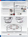
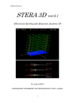
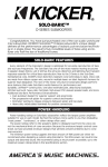
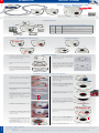
EN
PTMount
Quick Install
MX-PTMount-OPT
Security-Vision-Systems
PTMount for MOBOTIX S15D
Sensor Modules
6)
proof (IP6
Weather
to 140°F
2
2
/–
°C
0
–30 to +6
• S15D: Modular PoE network camera with max. two sensor modules for concealed installation (not included)
• All components weatherproof (S15D: IP65, sensor modules IP66),
–30 to +60°C/–22 to 140°F
• Day and Night sensor modules can be freely combined
• Sensor module connection cables max. 2 m each (e.g., for indoors/outdoors)
Manually adjustable dome mount for one MOBOTIX sensor
module housing S15D/S14D (not included), freely turning
along three axes,
for wall, ceiling and upright installations
Standard Delivery
1.1
1.9
1.2
1.8
1.7
1.3
1.6
1.5
Item
1.1
1.2
1.3
1.4
1.5
1.6
1.7
1.8
1.9
Count
1
1
1
1
1
4
4
4
1
Part Name
Sphere with freely rotating insert (installed)
Foot (installed)
Base plate (installed)
Swivel ring (installed)
Sealing
Washer Ø 4.3 mm, stainless steel
Wood screw 4x40 mm, stainless steel
Screw anchor S6
Allen wrench 2.5 mm
1.4
Adjustable Along Three Axes
Panning
Flexible Installation
Rotating
Mounting to a Ceiling
360°
360°
Mounting to a Wall
Mounting upright
100
°
Tilting
Preparatory Steps
• Using the supplied Allen wrench, remove the two screws that hold the
foot onto the swivel ring.
• Drill the holes for the base plate (drilling
template see Section «Dimensions/
Drilling Template»).
• Remove the swivel ring and the base
plate.
• In the center of the drilling template, drill
another hole into the wall or faceplate
for the sensor cable. Since you will
push the hinged ferrite through this
hole later on, the hole should have
a diameter between 15 and 35 mm.
• Make sure that there is enough space
for installing the PTMount and that
you can access it from the rear later
on. The surface should be even and
smooth so that the sealing lies flat
properly.
104 mm
• Insert the screw anchors into the holes,
if required.
Installation of PTMount and Sensor Module
• Attach the sensor module cable to
the sensor module (turn blue bayonet
catch to the left and remove, pull out
the plug, connect the sensor cable,
apply bayonet catch and lock by turning to the right).
• Push the sensor module into the
PTMount so that the MOBOTIX lettering is turned 90 degrees to the left
vs. the TOP/OBEN lettering.
TOP
OBE
N
BOTIX
• Attach the base plate using the supplied wood screws and washers.
MO
• Hold the sealing, the swivel ring and
the base plate as shown in the figure.
• When tightening the screws, make
sure that you can still rotate the swivel
ring by hand.
• Carefully guide the sensor cable
through the sealing, the swivel ring
and the base plate, then attach the
hinged ferrite to the cable.
• Push the sensor cable into the wall/
ceiling so as to completely hide the
ferrite.
TOP
• Using the module wrench (red or black),
lock the sensor module by turning it
90 degrees to the right.
MO
OBE
N
BOTIX
Max.
10 cm/4 in!
• Secure the sensor module by tightening the grub screw using the supplied
Allen wrench. The grub screw locks
the sensor module within the insert
and prevents inadvertent unlocking
of the sensor module.
• Guide the sensor cable from the back
into the foot and the sphere.
• Use the two screws to affix the foot
and sphere assembly to the swivel
ring and make sure that the foot can
still be rotated.
360°
1
• Loosen the two fastening screws of
the insert (1), then rotate the insert
so that the small bar opposite of the
TOP/OBEN label points to the hole of
the grub screw (2).
www.mobotix.com
• Secure the insert against rotating by
tightening the two fastening screws.
100
• Adjust the sensor module temporarily
by pointing it into the desired viewing
direction.
°
360°
2
• Make sure that the TOP/OBEN label
on the insert is pointing upwards. If
this is not the case, loosen the two
fastening screws and rotate the insert.
Lightly tighten the two fastening screws.
TOP
OBE
N
BO
MO TIX
Continue to bring the camera into service as described in Section «Initial
Operation S15D with PTMount».
Innovations – Made in Germany
The German company MOBOTIX AG is known as the leading pioneer in network camera technology and its decentralized concept has made high-resolution video
systems cost-efficient.
MOBOTIX AG • Security-Vision-Systems • D-67722 Langmeil • Phone: +49 6302 9816-103 • Fax: +49 6302 9816-190 • [email protected]
31.988_EN_V1_07/2014
MOBOTIX S15D
with 2 sensor modules, each in
PTMount
EN
PTMount
Quick Install
Initial Operation S15D with PTMount
Step 1: Establish Network Connection and Power Supply
Optional: Exchange the Sensor Modules in the Dual Image
• Connect the network port of the camera to a router or switch (see
S15 Camera Manual, Section «Network and Power Connection, Additional Cables»).
• In the camera's browser interface, click on the Admin Menu button
and in the Hardware Configuration section, open the Image Sensor
Configuration dialog.
• If you do not use a PoE switch, establish the power supply of the
camera (using a PoE Power Adapter/MX-NPA-Box).
• You can use the Left Sensor, Right Sensor dropdown fields to select
• Configure the camera for your network (see S15 Camera Manual,
Section «Manual and Automatic Operation»).
the sensor module (External sensor Cam1, External sensor Cam2) that
will be shown at the left or at the right in the dual image.
• Close the dialog and save the configuration of the camera.
Step 2: Open User Interface in Browser
• Monitor the camera LEDs and make sure that the S15D is ready (green
LED is on, red LED flashes slowly; see S15 Camera Manual, Section
«Camera Startup Sequence»).
• Enter the IP address of the camera you determined in Step 1 in the
address bar of the browser.
Step 3: Adjust PTMount According to Live Image
• Adjust the sensor module by watching the live image of the camera.
Firmly tighten all screws of the PTMount!
Make sure the power supply to the camera is disconnected before
installing or replacing a sensor module!
• If the small bar on the insert is not pointing towards the hole of the grub screw,
add a mark at the present position.
Remove the two fastening screws and
rotate the insert so that the small bar
points to the hole of the grub screw.
Tighten the two fastening screws.
• Use the Allen wrench or a small screwdriver to lift the sensor module out of
the insert as shown. Take care not
to damage the sealing of the sensor
module housing.
• Remove the bayonet catch and the
sensor cable from the old module.
Attach the sensor cable to the new
sensor module (connect the sensor
cable, apply bayonet catch and lock
by turning to the right).
• Loosen the grub screw that locks the
sensor module within the insert.
Insert the sensor module as described in Section «Installation of PTMount
and Sensor Module». If required, rotate the insert to its original position
and check the camera's live image as described in Section «Initial Operation S15D with PTMount». Tighten all screws you loosened before.
Example for wall installation
OBE
N
BOTIX
TOP
MO
• Using the module wrench (red or
black), unlock the sensor module by
turning it 90 degrees to the left.
Exchanging a Sensor Module
2014 • Declaration of Conformity: www.mobotix.com > Support > Media Library > Certificates
Security-Vision-Systems
Dimensions/Drilling Template
92 mm/3.62 in
94 mm/3.70 in (L12)
86 mm/3.39 in (L25 – L160)
104 mm/4.09 in
104 mm/4.09 in
in
60
m
8
.3
/1
m
m
/2
m
.3
6 35
in
10
0°
Tilt angle of sphere
Hole for cable
Swivel ring
(can be rotated)
Sealing
104 mm/4.09 in
Notes
• This product must not be used in locations exposed to the dangers
of explosion.
• Make sure that you install the S15D and this product as outlined in the
installation instructions in this document and in Chapter 2, «Installation»
of the S15 Camera Manual (www.mobotix.com > Support > Manuals).
• When installing this product, make sure that you are only using genuine
MOBOTIX parts and MOBOTIX connection cables.
• Only install this product in or on suitable, solid materials that provide
for a sturdy installation of the fixing elements used.
• The PTMount dome mount is only to be used in combination with the
MOBOTIX S15D and MOBOTIX sensor module housing.
• Make sure that the operating temperature of –30 to +60°C/–22 to 140°F
is not exceeded.
www.mobotix.com
The MOBOTIX YouTube Channel
www.youtube.com/MOBOTIXAG
Innovations – Made in Germany
The German company MOBOTIX AG is known as the leading pioneer in network camera technology and its decentralized concept has made high-resolution video
systems cost-efficient.
MOBOTIX AG • Security-Vision-Systems • D-67722 Langmeil • Phone: +49 6302 9816-103 • Fax: +49 6302 9816-190 • [email protected]
Copyright © MOBOTIX AG 2014 • Made in Germany • Technical information subject to change without notice.
Base plate
(mounted to wall/ceiling)