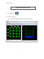
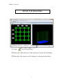
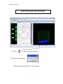
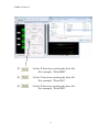
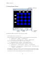
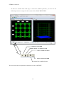
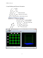
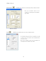
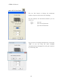
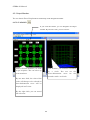
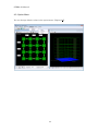
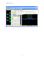
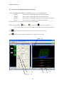
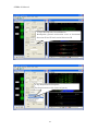
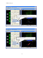
1
STERA 3D Manual STERA 3D ver.6.1 STructural Earthquake Response Analysis 3D Dr. Taiki SAITO TOYOHASHI UNIVERSITY OF TECHNOLOGY (TUT), JAPAN 1 STERA 3D Manual Preface This software is developed for the following analyses of reinforced concrete (RC) buildings: 1) Linear modal analysis, 2) Nonlinear static push-over analysis, 3) Nonlinear earthquake response analysis. This software is distributed for free for the use of research and educational purpose. Since this software is still under development, the author can not take any responsibility for the results of this software. It is greatly appreciated to have any opinions for future improvement. 12 September, 2005 Taiki SAITO E-mail: [email protected] Professor Toyohashi University of Technology, Japan 2 STERA 3D Manual Update history 2008/05/20 STERA_3D Ver.3.9 is uploaded. 2008/07/10 You can set isolation devices in the middle story. STERA_3D Ver.4.2 is uploaded. You can directly input material strength (steel and concrete). Masonry element is added. In Masonry and Damper Edit Views, you can set the upper beam types. 2009/01/12 The maximum number of element type is increased to be 30. STERA_3D Ver.4.3 is uploaded. You can change the default values for Column, Beam and Wall elements by Option Button in the Edit View. You can select NRB or LRB for the Isolator element. You can select Hysteresis Damper or Viscous Damper for the Damper element. 2009/10/22 2010/03/30 2010/05/06 2010/08/16 STERA_3D Ver.4.4 is uploaded. You can get the energy response in the time-history analysis. You can set more detail dimension for Beam and Column elements. STERA_3D Ver.4.5 is uploaded. Formulation of P-D effect is changed. Slight change of output format. STERA_3D Ver.4.6 is uploaded. You can select 100 member types. You can select 20 members for output of time-history response. STERA_3D Ver.4.7 is uploaded. You can set “default values” for member type. You can keep previous member settings after changing floor and span numbers. You can select response output for floors, nodes, and members from Option Menu. 2010/09/02 You can select 100 members for output of time-history response. STERA_3D Ver.4.8 is uploaded. You can get the response of side columns of wall element. When you select the folder of output files, the previous path of the folder will be displayed. 2010/10/25 STERA_3D Ver.4.9 is uploaded. 3 STERA 3D Manual Shear deformation at the beam-column connection is included. For beam elements, the shape of hysteresis model for nonlinear bending springs can be controlled by option parameters. For column elements, you can input X and Y direction shear reinforcements respectively. 2010/11/07 STERA_3D Ver.5.0 is uploaded. 2010/12/01 STERA_3D Ver.5.1 is uploaded. 2011/01/17 2011/03/07 2011/09/26 2011/11/15 2013/07/01 You can neglect nonlinear shear spring by option menu. You can set the value to amplify the original earthquake directly. The maximum spans are 30 in X spans and 20 in Y spans. STERA_3D Ver.5.5 is uploaded. The bug for Ai-distribution is fixed. The definition of mass distribution is improved. You can analyze L-shape wall or sequence walls. STERA_3D Ver.5.6 is uploaded. The equation of shear capacity of wall is modified. The number of input earthquake data is increased. You can get the axial deformation and force of base isolators. STERA_3D Ver.5.7 is uploaded. The bug in Masonry element is fixed. The bug in Flexible floor is fixed. STERA_3D Ver.5.9 is uploaded. Modified bi-linear model is added for Isolator Element. STERA_3D Ver.6.0 is uploaded. 2014/06/16 Unbalance force correction is newly added. STERA_3D Ver.5.8 is uploaded. 2014/04/03 The bug was fixed for yield rotation of nonlinear spring. STERA_3D Ver.5.4 is uploaded. 2012/02/27 The bug was fixed in case several walls are connected. The list of the space of shear reinforcement was modified. STERA_3D Ver.6.1 is uploaded. The definition of effective slab width is modified. Operator Splitting method is used instead of Force correction method for numerical integration. 4 STERA 3D Manual Quick User Manual 5 STERA 3D Manual READ BUILDING DATA ① Double Click ② “File” “Open” Select an example building “Structure7F.stera” 6 STERA 3D Manual MOVE THE BUILDING ① Click to be actual size. ② Drag the right mouse on the image to rotate the building. ③ Drag the left mouse on the image to enlarge and reduce. 7 STERA 3D Manual EARTHQUAKE RESPONSE ① Click to analyze the building. ② After the message, “Response Setting Dialog” will appear. 8 STERA 3D Manual ③ : Select X-direction earthquake data file. For example, “Kobe(EW)”. ④ : Select Y-direction earthquake data file. For example, “Kobe(NS)”. ⑤ : Select Z-direction earthquake data file. For example, “Kobe(UD)”. 9 STERA 3D Manual ⑥ : Start the response : Stop the response : Amplify the response : Reduce the response :: Change the view from double screen to single screen 10 STERA 3D Manual User Manual 11 STERA 3D Manual Basic Assumptions 1) In a default setting, the displacement freedom of a floor diaphragm is considered to be rigid for in-plane displacement and free for out-of-plane displacement. Elastic deformation of a floor diaphragm in-plane can be considered by the option menu. 2) All structural elements are modeled by line-elements with nonlinear springs except floor diaphragms which are modeled by FEM models. 3) Beam element is represented by a model with nonlinear flexural springs at the both ends and a nonlinear shear spring in the middle of the element, 4) Column element is represented by a MS (multi spring) model with nonlinear axial springs in the sections of the both ends and two directional nonlinear shear springs in the middle of the element, 5) Wall element is represented by a MS (multi spring) model with nonlinear axial springs in the sections of the both ends and nonlinear shear springs in the middle of the wall panel as well as in the two side columns, 6) Nonlinear springs are introduced for base-isolation elements or vertical elements at the basement. Base-isolation element is represented by the MSS (multi shear spring) model with nonlinear shear springs in X-Y plane, 7) Hysteresis damper and nonstructural element are introduced as nonlinear shear models, 8) The shear deformation of connection panel between beam and column is considered to be rigid or elastic.. 9) In a default setting, structural damping is proportional damping to initial stiffness. It can be changed to be proportional damping to instantaneous stiffness by the option menu. Other assumptions and details are written in “Technical Manual”. 12 STERA 3D Manual 1. File Arrangement Please check if you have the following files and folders in the folder “STERA 3D V*.*”: Stera 3D.exe … Main program response.exe … Sub-program for response output Stera7F.stera … Sample building Stera7F(SI).stera … Sample building with seismic isolation DataWaves … Folder of earthquake files OutFiles … Folder of output files (empty) If you change the places of these files, please put save two executable files; “Stera 3D.exe” and “response.exe” in a same folder. 13 STERA 3D Manual 2. Initial View Please double crick “Stera 3D.exe” The left view is “PLAN EDIT VIEW” where you input building plan data, and the right view is “3D VIEW” where you can see the building shape and its response after the analysis.. To open the building data already saved, [File] [Open], and select the file. PLAN EDIT VIEW 3D VIEW 14 STERA 3D Manual 3. Setting Element Pattern SPAN (mm) STORY WEIGHT STORY HEIGHT CURRENT STORY “PLAN EDIT VIEW” starts from 1st floor (1F) of a building. - Please click the place you want to set. - Please click again to change the element. It will be changed in the following order: Column (green) -- > Empty -- > Column(green) Beam (green) -- > Wall (dark green) -- > Empty -- > Beam (green) But, in case of the basement floor (BF), the order is changed as: Base Spring (brown) -- >Empty -- > Base Spring (brown) If you select Masonry element, Damper element and Isolator element, Column (green) -- > Isolator (brown) -- > Empty -- > Column(green) Beam (green) -- > Damper (brown) -- > Masonry (brown) -- > Wall (dark green) -- > Empty -- > Beam (green) - By dragging your mouse in a region, you can set all the elements in the region at once. - By clicking the right button of your mouse, you can change the element type number for column (C1-C100), for beam (B1-B100), and for wall (W1-W100) etc. 15 STERA 3D Manual - To move to another floor and copy or clear the member patterns, you can use the following buttons arranged at the bottom of the PLAN EDIT VIEW: CLEAR ALL PATTERN MOVE TO UPPER FLOOR COPY LOWER PATTERN COPY UPPER PATTERN MOVE TO LOWER FLOOR You can check the arrangement of members on the “3D VIEW”. 16 STERA 3D Manual 4. Input Building and Element Information COLUMN BEAM WALL CONNECTION PANEL NONSTRUCTURE (option) BASE SPRING (only BF) OUTPUT MEMBER BLACK AND WHITE MAX SIZE OF BUILDING SLAB (option) DAMPER (option) ISOLATOR (option) 17 STERA 3D Manual 4-1. Input Element Information COLUMN ( ) - Please input the section size where d1 and d2 are the distances of X-rebars and Y-rebars respectively. If rebars are arranged in two layers, the distance is determined as the center of rebar area. - For the number of reinforcement bars and their size, please select the values from the popup windows. - For the material strength, SD and Fc, you can input values by changing the default values. - To move to the next element type, please click [ADD] button. - You can copy the previous element by [COPY] button. - Please click [OK] to finish. - The default steel strength used for the analysis is assumed to be 1.1 times larger than the nominal strength. You can change the ratio in [OPTION] menu. 18 STERA 3D Manual - You can set default values for all members by selecting the last member type “Cdef”. 19 STERA 3D Manual BEAM ( ) - Please input the section size where d1 and d2 are the distances of upper rebars and bottom rebars respectively. If rebars are arranged in two layers, the distance should be the center of rebar area. - For the number of reinforcement bars and their size, please select the values from the popup windows. - For the material strength, SD and Fc, you can input values by changing the default values. - To move to the next element type, please click [ADD] button. - You can copy the previous element by [COPY] button. - You can set default values for all members by selecting the last member type “Bdef”. - Please click [OK] to finish. - The default steel strength used for the analysis is assumed to be 1.1 times larger than the nominal strength. - The effective slab width to contribute flexural behavior of beam is assumed to be 0.1 times beam length. The parameters to control the shape of hysteresis model are defined as follows: 20 - The default value of stiffness degrading ratio in the trilinear hysteresis is 0.5. (0: no degradation) - The default value of slip stiffness ratio in the trilinear hysteresis is 0.0 (0: no slip). - The default value of strength degrading ratio in the trilinear hysteresis is 0.0. - The default value of Ultimate rotation angle Ru is 1/50 (=0.02) - The default value of stiffness ratio over Ru is 0.001 (could be negative) STERA 3D Manual WALL ( ) - Please input the section size. - For the number of reinforcement bars and their size, please select the values from the popup windows. - For the material strength, SD and Fc, you can input values by changing the default values. - To move to the next element type, please click [ADD] button. - You can copy the previous element by [COPY] button. - You can set default values for all members by selecting the last member type “Wdef”. - Please click [OK] to finish. - The default steel strength used for the analysis is assumed to be 1.1 times larger than the nominal strength. You can change the ratio in [OPTION] menu. - If there is an opening in wall element, you can reduce the stiffness and shear strength factors by in multiplying [OPTION] default values are 1.0 21 reduction menu. The STERA 3D Manual CONNECTION PANEL ( ) Rigid Zone Panel Zone You can set the ratio of the length of rigid zone or panel zone inside connection area. The default value is 1.0 (to the member face). 22 STERA 3D Manual NONSTRUCTURE ( ) (NOTE: only available when you select in Option menu) - Please input the size of brick unit and thickness of mortal and compression strength of these materials. - If there is a reinforcement concrete beam upper of Masonry Wall as shown below, please select the beam type number from the pop-up menu. upper beam - You can set default values for all members by selecting the last member type “Mdef”. - If there is an opening in wall element, you can reduce the stiffness and shear strength factors by in multiplying [OPTION] default values are 1.0 23 reduction menu. The STERA 3D Manual ISOLATOR ( ) (NOTE: only available when you select in Option menu) - You can select NRB (Natural Rubber Bearing) for NRB Isolator or LRB (Lead Rubber Bearing) for Isolator element. - You can input the properties of isolator by [PROPERTY] view. - The default value of the ratio between vertical stiffness, Kv, and the horizontal stiffness, K0, is 1000. - You can set default values for all members by selecting the last member type “Idef”. for LRB Isolator - For LRB, there are two types of hysteresis model; one is Normal Bilinear model and another one is Modified Bilinear model. 24 STERA 3D Manual - Parameters for Modified Bilinear model are determined from material characteristics and the size of LRB. For the detail, please refer “STERA3D_technical_manual”. 25 to STERA 3D Manual DAMPER DEVICE ( ) (NOTE: only available when you select in Option menu) - Please select damper type from Elastic, Hystersis and Viscous and its detail characteristics from the pull down menu. - If there is a reinforcement concrete beam upper of Damper, please select the beam type number from the pop-up menu. - You can set default values for all members by selecting the last member type “Ddef”. - You can input the detail characteristic of the Damper in [PROPERTY] view. For Hysteresis Damper For Viscous Damper 26 STERA 3D Manual BASE SPRING ( ) (NOTE: only available at the Basement Floor, Default is PIN) - You can set default values for all members by selecting the last member type “Sdef”. VERTICAL SPRING SLAB ( ) (NOTE: only available when you select in Option menu.) - In a default setting, the slab is assumed to be rigid in plane. You can consider elastic deformation in the option menu. - You can set default values for all members by selecting the last member type “Fdef”. 27 STERA 3D Manual MAX. SIZE OF BUILDING ( ) You use this button to change the maximum number of spans and stories of the building. For the moment, the maximum numbers you can select are: Story Span : up to 61 : up to 30 in X-direction up to 20 in X-direction You can clear all building information by answering “YES” or you can keep the same building information after changing floor and span numbers by answering “NO”. 28 STERA 3D Manual 4-2. Output Member You can obtain Force-Displacement relationship of the designated member. OUTPUT MEMBER ( ) If you click this bottom, you can designate the output member. By one more click, you can cancel it. Please click the member you want The member you selected is marked to get response. You can select up by to 20 members. force-deformation a circle. You can see the curve for the member with a red circle. By one more click, the color of the circle will change to be red and its force-deformation curve will be displayed in 3D view. By the right click, you can cancel the selection. 29 STERA 3D Manual 4-3. Option Menu You can change default values in the option menu. [Option (O)] 30 STERA 3D Manual OPTION STRUCTURE [1] [2] [6] [3] [7] [4] [8] [5] [9] [1]. Restrained freedom number Please indicate the freedom numbers to restrain the freedoms. [2]. Floor Assumption Flexible Floor slab is modeled as a FEM model to consider in-plane elastic deformation. [3]. P-Delta Effect Considered P-Delta effect is considered in element stiffness matrix of column and wall. [4]. Nonlinear Shear Spring If it is not considered, shear spring is elastic. [5] Mass distribution at nodes in a floor [6]. Passive Damper Device [7]. Isolator [8]. Masonry Wall [9]. Young’s Modulus of Steel 31 STERA 3D Manual OPTION ANALYSIS STATIC Cyclic loading is possible controlling with the drift of the top of a building. 1. No. of Maximum Segment The total number of segments in cyclic loading, 2. No. of Separation of Segment Number of calculation steps in one segment for static analysis to increase the accuracy of nonlinear analysis, Loading program is defined by the target drift angle, D1, D2 … D150, at the top of a building in each loading segment. To move to the next angle, please click [ADD] button. 1. No. of Separation of Time Separating the original time interval of input earthquake into a smaller time interval will increase accuracy and stability in numerical integration, however, it also increase calculation time. For example, if the original time interval is 0.02sec and “No. of Separation of Time” = 5, then, the time interval of numerical integration will be 0.004 sec (= 0.02 sec / 5). The maximum data size multiplying number of input earthquake and separation number is 60,000. OPTION ANALYSIS DYNAMIC 2. Damping Three types of damping matrix are available: 1) [C] = a[K0] : proportional to [K0] 2) [C] = a[Kp] : proportional to [Kp] 3) [C] = a[K0]+b[M] : Rayleigh damping The first mode damping factor, h1, is used for type 1) and 2). The second mode damping factor, h2, is used for type 3). 3. Numerical Integration Method You can select the method from the Average Acceleration Method and the Operetor Splitting Method. 32 STERA 3D Manual OPTION ANALYSIS OUTPUT You can select response output to create files to save data. 1. Floor response Output of story displacement and shear force at the center of gravity in each floor will be saved. It is marked as a default setting. 2. Nodal response Output of deformation and external force at all nodes will be saved. Note that the file size will be quite large. It is not marked as a default setting. 3. Member response Response of the members marked by circles will be saved. It is marked as a default setting. 33 STERA 3D Manual 5. 3D View of Building 5-1. 3D View of Building [1] [Default] ( [2] [Actual] ( ) set the ratio between span and story height as 1 and 0.5. ) use the actual ratio between span and story height using input data. MOVE ROTATION ENLARGE / REDUCE ACTUAL SIZE DEFAULT SIZE [3] You can change the view by moving the mouse as follows: - Rotation: Left-click and dragging - Enlargement and Reduction: Right click and dragging 34 STERA 3D Manual [4] If the [Analyze] ( ) is activated, by clicking the button, you can make an initial analysis for getting natural periods and mode shapes. [5] If the analysis is successfully done, the following message will appear on the screen. By click [OK] button, RESPONSE SETTING DIALOG will also appear. RESPONSE SETTING DIALOG 35 STERA 3D Manual 5-2. Modal Analysis [1] On the RESPONSE SETTING DIALOG, please click the MODE number from [0] to [6] to see the view of mode shape and the value of natural period. [2] On the 3D VIEW, ( ) stops the vibration ) pauses the vibration. and ( [3] ( ) starts the vibration of each mode, ( ) amplifies the response. ( [4] Slider ( ) reduces the response. ) changes the speed of vibration. [5] ( ) will save the results into text files. [6] ( ) changes the color of the view to be black and white. [5] Save data [6] Black and White [4] Speed [1] Response Setting [3] Amplify / Reduce [2] Play / Stop 36 STERA 3D Manual 5-3. Nonlinear Static Push-Over Analysis [1] Please set loading conditions for the STATIC LOAD: “Direction”: please select loading direction from the menu. 1. X “Distribution”: 2. –X (opposite to X) 3. Y 4. -Y (opposite to Y) please select a loading distribution along the height of the building. The load is applied at the center of gravity in each floor. 1. Ai “Target Drift”: 2. Triangular 3. Uniform 4. UBC 5. Mode please set the target drift ratio which is defined by the ratio between the top displacement and the height of the building. 1. 1/50 2. 1/100 3. 1/200 4. Cyclic [2] Please select the response for the lower view window. [3] On the 3D VIEW, ( ) starts, ( ) pauses and ( ) stops the response. In the upper view, you can see an arrow under the building to indicate the loading direction, also a progressing bar, and colors of ductility factors (U). [4] ( ) will change the view from 2-screens to 1-screen and vise versa. [1] [2] [3] 37 [4] STERA 3D Manual 1: Drift-Shear Relation Relationship between Story Drift and Story Shear Coefficient (Story Shear / Total Weight) 2: Capacity Curve Capacity curve for equivalent 1DOF system 38 STERA 3D Manual 3: Member Response M-θ relationships of the designated member (with ○): - both ends for Beam 39 - X and Y at bottom for Column STERA 3D Manual 5-4. Nonlinear Earthquake Response Analysis [1] On the RESPONSE SETTING DIALOG, please set earthquake data: “File(X)”: Please select earthquake input file for X-direction. “File(Y)”: Please select earthquake input file for Y-direction. “File(Z)”: Please select earthquake input file for Z-direction (up-down). “Power”: Set the value to amplify the original earthquake [2] Please select the response for the lower view window. [3] On the 3D VIEW, ( ) starts, ( ) pauses and ( ) stops the response. In the lower view, you can see the input earthquake wave and present status. [4] ( ) will change the view from 2-screen to 1-screen and vise versa. [5] ( ) will save the response animation as a movie file (see 5-5). [5] [2] [1] 40 [3] [4] STERA 3D Manual 1: Input Earthquake Ground Motion Earthquake ground acceleration wave in horizontal direction (X and Y) and vertical direction (Z) 2: Top Displacement Response Top displacement at the center of gravity 41 STERA 3D Manual 3: Orbit of Top Displacement Orbit of the top displacement at the center of gravity 4: Base Shear - Top Drift Top displacement and base shear force relationship 42 STERA 3D Manual 5: Energy Response K: Kinematics Energy N: Energy dissipation by Nonlinear Dampers F: Energy dissipation by Frame members D: Energy dissipation by Viscous Damper 6: Member Response M-θ relationships of the designated member: - both ends for Beam 43 - X and Y at bottom for Column STERA 3D Manual Format of input earthquake data file When you prepare an input earthquake file by yourself, please arrange the data format as follows: Order Type Information Comments 1st data INT 0 or 1 0: Earthquake ground acceleration data only 1: Earthquake ground acceleration data and (ID) ground displacement data 2nd data INT Number of data (NDATA) 3rd data If ID=1, the number of data for acceleration must be the same as that for displacement. REAL Time interval (sec) REAL Acceleration 1, 2, …, NDATA (cm/sec2) Displacement 1, 2, …, NDATA (cm) (DT) 4th data and later The maximum data size multiplying number of input earthquake (NDATA) and separation number (NDIV) is 60,000. ( NDATA * NDIV < 60,000 ). Example) 0 750 0.020 -1.40 -10.80 -10.10 -8.80 -9.50 -12.00 -14.20 -12.80 -11.00 -8.50 -8.50 -13.10 -17.60 -19.40 -16.20 -14.40 -10.80 -8.20 -4.20 -6.60 -13.10 -19.00 -19.60 -6.60 3.00 14.10 -4.90 -12.80 -14.40 -20.30 -26.00 -32.50 -30.60 -17.20 -19.70 44 STERA 3D Manual 5-5. Save Nonlinear Earthquake Response as a Movie File Generally, it takes long time to calculate earthquake response of a building. You can save the response of the building in a movie file and later you can open the movie to see the response quickly. 1) Record movie [1] On the RESPONSE SETTING DIALOG, please select earthquake input files in the menu “EARTHQUAKE”. [2] Please push the movie button ( [3] ( ) displays the response. ( ) and write the file name such as “Movie.txt”. ) stops the response. [1] [2] [3] 45 STERA 3D Manual 2) Play movie [1] On the RESPONSE SETTING DIALOG, please push in the “MOVIE” menu to select a movie file. [2] ( ) displays, ( ) pauses and ( ) stops the response. [1] [2] 46 STERA 3D Manual 5-6. Change Analysis [1] On the RESPONSE SETTING DIALOG, you can change the analysis: Mode: Modal Analysis Static: Nonlinear Static Push-Over Analysis Earthquake: Nonlinear Earthquake Response Analysis Movie: Movie for Nonlinear Earthquake Response Analysis [1] 47 STERA 3D Manual 6. Save and Open Files 6-1. Save Building Data You can save the building data in a file and open it later. The file has an extension “.stera”. NEW FILE OPEN FILE SAVE FILE 48 STERA 3D Manual 6-2. Save Results of Analysis into Text Files To save the results of analysis in text files, you must run another program. [1] On the RESPONSE SETTING DIALOG, please set the condition of analysis. [2] Please push the “Save Data” button ( ). [3] Please select folder to save output files. [2] [1] [3] [4] 49 STERA 3D Manual [4] When you push “OK”, a window appears to start calculation and save output data to the designated folder. 50 STERA 3D Manual In the designated folder, the following files are automatically created: data_*** structural data of elements or structure max_*** maximum response of elements or structure response_eccentricity: eccentricity and rigigity ratio response_eigen : natural periods and mode shapes response_member01,02,… : member response response_node : nodal resposne response_structure : story response beam : Beam column : Column wall : Wall damper : Damper and Nonstructural wall spring : Vertical spring bi : Base Isolator structure : Building 51 STERA 3D Manual 1) “response_eigen.txt” In this file, the results of modal analysis including natural periods, mode vectors, stimulus functions are saved. Natural Period Mode Vector 52 Stimulus Function STERA 3D Manual 2) “response_structure.txt” [1] In case of nonlinear static analysis, the following data are saved for each story. kstep calculation step in static analysis < Equivalent 1DOF system> sd displacement (cm) sa acceleration (gal) <Relative story displacement> F story number sdx story drift in X-direction (cm) sdy story drift in Y-direction (cm) srz rotational angle around Z-direction (torsion angle) <Story shear force> sfx story shear force in X-direction (kN) sfy story shear force in Y-direction (kN) <Displacement from the ground at the center of gravity in each floor> dx displacement in X-direction (cm) dy displacement in Y-direction (cm) rz rotational angle around Z-direction [2] In case of earthquake response analysis, the following data are saved for each story: t time step in dynamic analysis <Relative story displacement> F story number sdx story drift in X-direction (cm) sdy story drift in Y-direction (cm) srz rotational angle around Z-direction (torsion angle) <Story shear force> sfx story shear force in X-direction (kN) sfy story shear force in Y-direction (kN) <Displacement from the ground at the center of gravity in each floor> dx displacement in X-direction (cm) dy displacement in Y-direction (cm) rz rotational angle around Z-direction 53 STERA 3D Manual 3) “response_eccentricity.txt” This file includes the output of eccentricity ratio and rigidity ratio based on Japanese standards. 0 F : basement floor 54 STERA 3D Manual 4) “response_member.txt” [1] In case of Beam < Moment > Disp. Force. Rya Mya Rpa Mpa Ryb Myb Rpb Mpb < Shear Force > Disp. Force. Rsx Qsx Ductility Factor Uya End A Upa End B Uyb Nonlinear Rotational Spring at End A Upb Nonlinear Rotational Spring at End B Ductility Factor Usx Nonlinear Shear Spring [2] In case of Column < Moment > Disp. Force. Rya Mya Ryb Myb Rxa Mxa Rxb Mxb < Shear Force > Disp. Force. Rsx Qsx Rsy Qsy <Axial Force> Disp Force Dz Nz < Multi-spring > Disp. Force. C1D(a) C1F(a) C2D(a) C2F(a) C3D(a) C3F(a) C4D(a) C4F(a) C5D(a) C5F(a) S1D(a) S1F(a) S2D(a) S2F(a) S3D(a) S3F(a) S4D(a) S4F(a) S5D(a) S5F(a) C1D(b) C1F(b) C2D(b) C2F(b) C3D(b) C3F(b) C4D(b) C4F(b) C5D(b) C5F(b) S1D(b) S1F(b) S2D(b) S2F(b) Ductility Factor Uya Uyb Uxa Uxb End A End B End A End B Ductility Factor Usx Usy Nonlinear Shear Spring Nonlinear Shear Spring (Bottom) (Bottom) (Bottom) (Bottom) Y-direction Y-direction X-direction X-direction Total Force from Spring Nz2 Ductility Factor C1U(a) C2U(a) C3U(a) C4U(a) C5U(a) S1U(a) S2U(a) S3U(a) S4U(a) S5U(a) C1U(b) C2U(b) C3U(b) C4U(b) C5U(b) S1U(b) S2U(b) End A End A End A End A End A End A End A End A End A End A End B End B End B End B End B End B End B 55 Concrete Spring 1 Concrete Spring 2 Concrete Spring 3 Concrete Spring 4 Concrete Spring 5 Steel Spring 1 Steel Spring 2 Steel Spring 3 Steel Spring 4 Steel Spring 5 Concrete Spring 1 Concrete Spring 2 Concrete Spring 3 Concrete Spring 4 Concrete Spring 5 Steel Spring 1 Steel Spring 2 X-direction Y-direction STERA 3D Manual S3D(b) S4D(b) S5D(b) S3F(b) S4F(b) S5F(b) S3U(b) S4U(b) S5U(b) End B End B End B Steel Spring 3 Steel Spring 4 Steel Spring 5 [3] In case of Wall < Moment > Disp. Force. Ductility Factor Rya Mya Uya End A (Bottom) Y-direction Ryb Myb Uyb End B (Bottom) Y-direction Rxa Mxa Uxa End A (Bottom) X-direction Rxb Mxb Uxb End B (Bottom) X-direction < Shear Force > Disp. Force. Ductility Factor Rsx Qsx Usx Nonlinear Shear Spring X-direction <Axial Force> Disp Force Total Force from Spring Dz Nz Nz2 < Multi-spring > (springs 11-15 in a wall panel) Disp. Force. Ductility Factor C11D(a) C11F(a) C11U(a) End A Concrete Spring 11 C12D(a) C12F(a) C12U(a) End A Concrete Spring 12 C13D(a) C13F(a) C13U(a) End A Concrete Spring 13 C14D(a) C14F(a) C14U(a) End A Concrete Spring 14 C15D(a) C15F(a) C15U(a) End A Concrete Spring 15 S11D(a) S11F(a) S11U(a) End A Steel Spring 11 S12D(a) S12F(a) S12U(a) End A Steel Spring 12 S13D(a) S13F(a) S13U(a) End A Steel Spring 13 S14D(a) S14F(a) S14U(a) End A Steel Spring 14 S15D(a) S15F(a) S15U(a) End A Steel Spring 15 C11D(b) C11F(b) C11U(b) End B Concrete Spring 11 C12D(b) C12F(b) C12U(b) End B Concrete Spring 12 C13D(b) C13F(b) C13U(b) End B Concrete Spring 13 C14D(b) C14F(b) C14U(b) End B Concrete Spring 14 C15D(b) C15F(b) C15U(b) End B Concrete Spring 15 S11D(b) S11F(b) S11U(b) End B Steel Spring 11 S12D(b) S12F(b) S12U(b) End B Steel Spring 12 S13D(b) S13F(b) S13U(b) End B Steel Spring 13 S14D(b) S14F(b) S14U(b) End B Steel Spring 14 S15D(b) S15F(b) S15U(b) End B Steel Spring 15 [4] In case of Vertical Spring < Axial Force > Disp. Force. Dz Fz Ductility Factor Uz [5] In case of Base Isolator < Shear Force and Axial Force> Disp. Force. Ductility Factor Dx Qx Ux Dy Qy Uy Dv Fv X-direction (Shear) Y-direction (Shear) Z-direction (Axial) [6] In case of Damper and Nonstructural Wall < Shear Force > Disp. Force. Dx Qx Ductility Factor Ux X-direction 56 STERA 3D Manual 7) “response_node.txt” Node number in each floor kstep node < Displacement> dx dy dz rx ry rz <Force> fx fy fz calculation step in static analysis node number displacement in X-direction (cm) displacement in Y-direction (cm) displacement in Z-direction (cm) rotational angle around X-direction rotational angle around Y-direction rotational angle around Z-direction ) force in X-direction (kN) force in Y-direction (kN) force in Z-direction (kN) 57 STERA 3D Manual 6) “max_****.txt” In this file, the maximum stress and displacement of each member and the maximum story responses are saved. [1] “max_baem.txt” Ductility factor Beam M at the end of flexural part A M at the nonlinear spring A M at the end of flexural part B M at the nonlinear spring B Q M A Moment distribution B M MY BE M M M My My k0 Mc k 0 y k0 c y 6 EI l = + kp k0 c y Elastic element [2] “max_column.txt” Mc Nonlinear bending spring Column MX: Moment in X-direction MY: Moment in Y-direction ST: Steel CO : Concrete Q : Shear N: Axial force 58 STERA 3D Manual [3] “max_wall.txt”, Wall MY: Moment at the wall panel MXA, MAB: Moment at the side columns A and B ST: Steel CO : Concrete Q1 : Shear at the wall panel Q2, Q3: Shear at the side columns A and B N: Axial force 59 STERA 3D Manual [4] “max_structure.txt” Floor response F story number h story height (cm) <Maximum relative story displacement> sdx story drift in X-direction (cm) sdy story drift in Y-direction (cm) ssx story drift in X-direction (cm), shear component ssy story drift in Y-direction (cm), shear component <Maximum story shear force> sfx story shear force in X-direction (kN) sfy story shear force in Y-direction (kN) <Maximum displacement from the ground at the center of gravity in each floor> dx displacement in X-direction (cm) dy displacement in Y-direction (cm) rz rotational angle around Z-direction 60 STERA 3D Manual 7) “data_****.txt” To know the member number and member properties, please refer to “data_***.txt”. Member number C---B---C---B---C--| B | C | Properties 61


![20 [7] Don Libes, “Using expect to Automate Systems Administration](http://vs1.manualzilla.com/store/data/005773716_1-68a79e060d9ea16881001f4ab808f924-150x150.png)