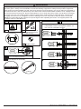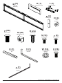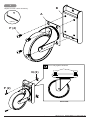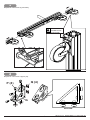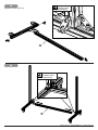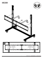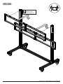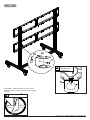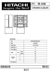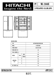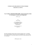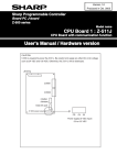
1
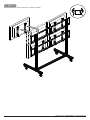
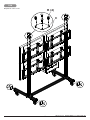
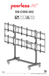
DS-C560-2X2
46"-60"
(117cm-152cm)
MAX
500 lb
(227 kg)
ENG
1
2014-04-14 #:009-9082-3.1 (2014-08-19)
This page intentionally left blank.
2
2014-04-14 #:009-9082-3.1 (2014-08-19)
WARNING
Do not begin to install product until you have read and understood the instructions and warnings contained in
this user guide. Always use an assistant or mechanical lifting equipment to safely lift and position equipment.
This product must be installed onto flat, hard, level surface to prevent tipping. The cart or stand is not affixed or
secured to the floor, and may therefore tip over and/or fall if screen and/or stand is shaken or hit. Displays must
be removed before moving cart. Not recommended for use in areas with heavy traffic. This product is intended
for indoor use only. Use of this product outdoors could lead to product failure or personal injury. Screws must
be tightly secured. Do not overtighten screws or damage can occur and product may fail. Never exceed the
Maximum Load Capacity. Be careful not to pinch fingers when operating the mount. For support please call
customer care at 1-800-865-2112.
ENG Symbols
ENG WARNING
x3
1
ENG Screws must get at
least three full turns
and fit snug.
To properly tighten screws: Tighten until screw
head makes contact, then tighten another 1/2
turn. Do not overtighten screws.
2
Heavy
ENG Display center.
3
+1/2
ENG Do not overtighten screws.
ENG Tools Needed for Assembly.
4
(13mm)
3
2014-04-14 #:009-9082-3.1 (2014-08-19)
Parts (Before beginning, make sure you have all parts shown below).
Parts List
A
B
C
D
E
F
G
H
I
J
K
L
M
N
O
P
Q
R
S
T
U
V
W
X
Y
Description
caster, 5" swivel
caster support
cover
base leg
horizontal leg support
base support tube
base support
vertical leg support
adaptor bracket
vertical support bracket
computer cover
computer shelf
dual rail assembly
locking tab
cord bracket
M8 x 16mm socket button screw
M8 square nut
cover clip
M5 x 10mm type-f, socket pin screw
M5 x 12mm socket pin screw
1/4" power bit
5mm allen wrench
nylon shoulder washer
M6 x 12mm socket pin screw
4mm allen wrench
A (4 )
caster
B (4 )
caster support
Qty
4
4
6
2
1
2
6
2
8
4
1
1
2
4
4
96
56
24
10
4
1
1
16
16
1
C (6 )
F (2 )
cover
base support
tube
D (2 )
G (6 )
base support
Part #
600-0026
145-T1799
145-T1809
145-T1767
145-T1785
145-T1812
560-T1261
145-T1777
145-T1792
145-T1806
145-T1930
145-T1931
145-T1924
145-T1936
145-T1929
520-9527
530-1066
590-0317
520-1164
520-1064
560-0263
560-9640
590-2233
520-1050
560-9646
I (8 )
adaptor bracket
J (4 )
base leg
vertical support
bracket
E (1 )
horizontal leg
support
H (2 )
vertical leg
support
4
2014-04-14 #:009-9082-3.1 (2014-08-19)
K (1 )
M (2 )
L (1 )
computer shelf
computer cover
dual rail
assembly
N (4 )
locking tab
O (4 )
cord
bracket
P (96)
M8 x 16mm
Q (56)
M8 square nut
R (24)
cover clip
S (10)
M5 x 10mm
U (1 )
V (1 )
1/4" power
bit
5mm allen
wrench
W (16)
nylon shoulder
washer
T (4 )
M5 x 12mm
X (16)
M6 x 12mm
Y (1 )
4mm allen
wrench
5
2014-04-14 #:009-9082-3.1 (2014-08-19)
1
B
Repeat for each caster assembly.
Y
A
(5mm)
P (4)
Do not fully tighten hardware
Q (2)
P (2)
SIDE VIEW
6
2014-04-14 #:009-9082-3.1 (2014-08-19)
2
Repeat for each base leg assembly.
Y
Q (2)
(5mm)
Q (2)
D
F
P (4)
Q (2)
Q (2)
F
P (4)
7
2014-04-14 #:009-9082-3.1 (2014-08-19)
3
Repeat for each base leg assembly.
TIGHTEN
CONNECTING
HARDWARE
4
Repeat for each base support (x6).
Q (4)
P (4)
G
SIDE VIEW
8
2014-04-14 #:009-9082-3.1 (2014-08-19)
5
TIGHTEN
CONNECTING
HARDWARE
Repeat for each side (x2).
H
6
TIGHTEN
CONNECTING
HARDWARE
E
9
2014-04-14 #:009-9082-3.1 (2014-08-19)
7
Repeat for each vertical
support bracket (x4).
1/8"
(3mm)
1/8"
(3mm)
Q (4)
P (4)
J
P (2)
J (2)
DIS
J (2)
PL
10
AY
H
EIG
HT
2014-04-14 #:009-9082-3.1 (2014-08-19)
8
M
TIGHTEN
HARDWARE
(X2)
TIGHTEN
HARDWARE
(X2)
Cross supports must center on vertical leg supports.
11
2014-04-14 #:009-9082-3.1 (2014-08-19)
9
TIGHTEN
CONNECTING
HARDWARE (X4)
12
2014-04-14 #:009-9082-3.1 (2014-08-19)
14
N
O
T
TIGHTEN
CONNECTING
HARDWARE
N
O
OPTIONAL: Unlock wheels to move cart to
desired location; Lock wheels before hanging
screens.
T
TOP VIEW
LOCK WHEELS
13
2014-04-14 #:009-9082-3.1 (2014-08-19)
10
Center adapter brackets vertically on back of screen.
X
.98"
(25mm)
7.87"
(200mm)
3.94"
(100mm)
2.50"
(63mm)
15.75"
(400mm)
X
2.50"
(63mm)
0.91"
(23mm)
W X
P
OR
14
x3
2014-04-14 #:009-9082-3.1 (2014-08-19)
11
Hook on displays and secure pin in "locked" position.
15
2014-04-14 #:009-9082-3.1 (2014-08-19)
Display Adjustment
IN
OUT
SIDE
SIDE
TILT BACKWARD
SIDE
TILT RIGHT
TILT LEFT
TOP
SIDE
UP
TILT FORWARD
TOP
DOWN
ROTATE LEFT
16
ROTATE RIGHT
2014-04-14 #:009-9082-3.1 (2014-08-19)
12
L
13
1/8"
(3mm)
L
K
S (2)
TIGHTEN
CONNECTING
HARDWARE
L
17
2014-04-14 #:009-9082-3.1 (2014-08-19)
15
Repeat for each cover.
R (4)
C
18
2014-04-14 #:009-9082-3.1 (2014-08-19)
16
Route cables through cord brackets.
O
O
19
2014-04-14 #:009-9082-3.1 (2014-08-19)
LIMITED FIVE-YEAR WARRANTY
Peerless Industries, Inc. (“Peerless”) warrants to original end-users of Peerless® products will be free from defects in material and
workmanship, under normal use, for a period of five years from the date of purchase by the original end-user (but in no case longer than
six years after the date of the product's manufacture). At its option, Peerless will repair or replace, or refund the purchase price of, any
product which fails to conform with this warranty.
In no event shall the duration of any implied warranty of merchantability or fitness for a particular purpose be longer than the
period of the applicable express warranty set forth above. Some states do not allow limitations on how long a implied warranty lasts,
so the above limitation may not apply to you.
This warranty does not cover damage caused by (a) service or repairs by the customer or a person who is not authorized for such service
or repairs by Peerless, (b) the failure to utilize proper packing when returning the product, (c) incorrect installation or the failure to follow
Peerless' instructions or warnings when installing, using or storing the product, or (d) misuse or accident, in transit or otherwise, including
in cases of third party actions and force majeure.
In no event shall Peerless be liable for incidental or consequential damages or damages arising from the theft of any product,
whether or not secured by a security device which may be included with the Peerless® product. Some states do not allow the
exclusion or limitation of incidental or consequential damages, so the above limitation or exclusion may not apply to you.
This warranty is in lieu of all other warranties, expressed or implied, and is the sole remedy with respect to product defects. No dealer,
distributor, installer or other person is authorized to modify or extend this Limited Warranty or impose any obligation on Peerless in
connection with the sale of any Peerless® product.
This warranty gives specific legal rights, and you may also have other rights which vary from state to state.
Peerless-AV
2300 White Oak Circle
Aurora, IL 60502
Email: [email protected]
Ph: (800) 865-2112
Fax: (800) 359-6500
www.peerless-av.com
Peerless-AV Europe
Unit 3 Watford Interchange,
Colonial Way, Watford, Herts,
WD24 4WP, United Kingdom
Customer Care
44 (0) 1923 200 100
www.peerless-av.com
Peerless-AV de Mexico
Ave de las Industrias 413
Parque Industrial Escobedo
Escobedo N.L Mexico 66050
Servicio al Cliente
01-800-849-65-77
www.peerless-av.com
© 2013, Peerless Industries, Inc.
© 2013, Peerless Industries, Inc.
© 2013, Peerless Industries, Inc.