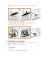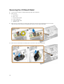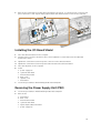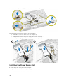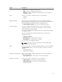
1
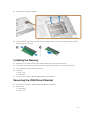
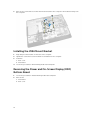
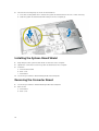
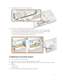
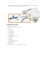
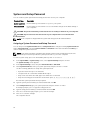
Dell OptiPlex 9030 All-In-One
Owner's Manual
Regulatory Model: W09C
Regulatory Type: W09C001
Notes, Cautions, and Warnings
NOTE: A NOTE indicates important information that helps you make better use of your computer.
CAUTION: A CAUTION indicates either potential damage to hardware or loss of data and tells you
how to avoid the problem.
WARNING: A WARNING indicates a potential for property damage, personal injury, or death.
Copyright © 2014 Dell Inc. All rights reserved. This product is protected by U.S. and international copyright and
intellectual property laws. Dell™ and the Dell logo are trademarks of Dell Inc. in the United States and/or other
jurisdictions. All other marks and names mentioned herein may be trademarks of their respective companies.
2014 - 06
Rev. A00
Contents
1 Working on Your Computer................................................................................... 5
Before Working Inside Your Computer................................................................................................ 5
Recommended Tools............................................................................................................................6
Turning Off Your Computer..................................................................................................................7
After Working Inside Your Computer................................................................................................... 7
Important Information.......................................................................................................................... 8
2 Removing and Installing Components................................................................9
System Overview................................................................................................................................... 9
Removing the VESA Stand.................................................................................................................. 10
Installing the VESA Stand..................................................................................................................... 11
Removing the Back Cover................................................................................................................... 11
Installing the Back Cover.....................................................................................................................12
Removing the Memory........................................................................................................................12
Installing the Memory..........................................................................................................................13
Removing the VESA Mount Bracket....................................................................................................13
Installing the VESA Mount Bracket......................................................................................................14
Removing the Power and On-Screen Display (OSD) Buttons Board................................................14
Installing the Power and OSD Buttons Board.................................................................................... 15
Removing the System-Board Shield................................................................................................... 15
Installing the System-Board Shield.....................................................................................................16
Removing the Converter Board.......................................................................................................... 16
Installing the Converter Board............................................................................................................ 17
Removing the Coin-Cell Battery.........................................................................................................18
Installing the Coin-Cell Battery...........................................................................................................18
Removing the Optical Drive................................................................................................................18
Installing the Optical Drive................................................................................................................. 20
Removing the Hard Drive................................................................................................................... 20
Installing the Hard Drive...................................................................................................................... 21
Removing the Intrusion Switch.......................................................................................................... 22
Installing the Intrusion Switch............................................................................................................ 23
Removing the Wireless Local Area Network (WLAN) Card................................................................23
Installing the WLAN Card....................................................................................................................24
Removing the Heatsink Assembly...................................................................................................... 24
Installing the Heatsink Assembly........................................................................................................ 24
Removing the Processor Fan..............................................................................................................25
Installing the Processor Fan................................................................................................................26
Removing the Power-Supply Fan.......................................................................................................26
Installing the Power-Supply Fan......................................................................................................... 27
Removing the I/O Board Shield..........................................................................................................28
Installing the I/O Board Shield............................................................................................................29
Removing the Power Supply Unit (PSU).............................................................................................29
Installing the Power Supply Unit........................................................................................................ 30
Removing the Processor..................................................................................................................... 31
Installing the Processor....................................................................................................................... 31
Removing the Speakers...................................................................................................................... 32
Installing the Speakers........................................................................................................................ 33
Removing the System Board.............................................................................................................. 34
System Board Layout.......................................................................................................................... 35
Installing the System Board................................................................................................................ 36
Removing the Display Panel............................................................................................................... 37
Installing the Display Panel................................................................................................................. 39
Removing the Camera........................................................................................................................40
Installing the Camera.......................................................................................................................... 41
3 System Setup........................................................................................................... 42
Boot Sequence....................................................................................................................................42
Navigation Keys................................................................................................................................... 42
System Setup Options.........................................................................................................................43
Updating the BIOS ..............................................................................................................................53
System and Setup Password...............................................................................................................54
Assigning a System Password and Setup Password.................................................................... 54
Deleting or Changing an Existing System and/or Setup Password.............................................55
4 Technical Specifications.......................................................................................56
5 Contacting Dell....................................................................................................... 61
Working on Your Computer
1
Before Working Inside Your Computer
Use the following safety guidelines to help protect your computer from potential damage and to help to
ensure your personal safety. Unless otherwise noted, each procedure included in this document assumes
that the following conditions exist:
•
You have read the safety information that shipped with your computer.
•
A component can be replaced or--if purchased separately--installed by performing the removal
procedure in reverse order.
WARNING: Disconnect all power sources before opening the computer cover or panels. After you
finish working inside the computer, replace all covers, panels, and screws before connecting to
the power source.
WARNING: Before working inside your computer, read the safety information that shipped with
your computer. For additional safety best practices information, see the Regulatory Compliance
Homepage at www.dell.com/regulatory_compliance
CAUTION: Many repairs may only be done by a certified service technician. You should only
perform troubleshooting and simple repairs as authorized in your product documentation, or as
directed by the online or telephone service and support team. Damage due to servicing that is
not authorized by Dell is not covered by your warranty. Read and follow the safety instructions
that came with the product.
CAUTION: To avoid electrostatic discharge, ground yourself by using a wrist grounding strap or
by periodically touching an unpainted metal surface, such as a connector on the back of the
computer.
CAUTION: Handle components and cards with care. Do not touch the components or contacts
on a card. Hold a card by its edges or by its metal mounting bracket. Hold a component such as a
processor by its edges, not by its pins.
CAUTION: When you disconnect a cable, pull on its connector or on its pull-tab, not on the cable
itself. Some cables have connectors with locking tabs; if you are disconnecting this type of cable,
press in on the locking tabs before you disconnect the cable. As you pull connectors apart, keep
them evenly aligned to avoid bending any connector pins. Also, before you connect a cable,
ensure that both connectors are correctly oriented and aligned.
NOTE: The color of your computer and certain components may appear differently than shown in
this document.
5
To avoid damaging your computer, perform the following steps before you begin working inside the
computer.
1.
Ensure that your work surface is flat and clean to prevent the computer cover from being scratched.
2.
Turn off your computer (see Turning Off Your Computer).
CAUTION: To disconnect a network cable, first unplug the cable from your computer and
then unplug the cable from the network device.
3.
Disconnect all network cables from the computer.
4.
Disconnect your computer and all attached devices from their electrical outlets.
5.
Press and hold the power button while the computer is unplugged to ground the system board.
6.
Remove the cover.
CAUTION: Before touching anything inside your computer, ground yourself by touching an
unpainted metal surface, such as the metal at the back of the computer. While you work,
periodically touch an unpainted metal surface to dissipate static electricity, which could
harm internal components.
Recommended Tools
The procedures in this document may require the following tools:
•
Small flat-blade screwdriver
•
Phillips screwdriver
•
Small plastic scribe
6
Turning Off Your Computer
CAUTION: To avoid losing data, save and close all open files and exit all open programs before
you turn off your computer.
1.
Shut down the operating system:
•
In Windows 8.1:
– Using a touch-enabled device:
a.
Swipe in from the right edge of the screen, opening the Charms menu and select
Settings.
b.
Select the
and then select Shut down.
– Using a mouse:
•
a.
Point to upper-right corner of the screen and click Settings.
b.
Click the
and select Shut down.
In Windows 7:
1.
Click Start
.
2.
Click Shut Down.
or
2.
1.
Click Start
.
2.
Click the arrow in the lower-right corner of the Start menu as shown below, and then click
Shut Down
.
Ensure that the computer and all attached devices are turned off. If your computer and attached
devices did not automatically turn off when you shut down your operating system, press and hold
the power button for about 6 seconds to turn them off.
After Working Inside Your Computer
After you complete any replacement procedure, ensure you connect any external devices, cards, and
cables before turning on your computer.
1.
Replace the cover.
CAUTION: To connect a network cable, first plug the cable into the network device and then
plug it into the computer.
2.
Connect any telephone or network cables to your computer.
3.
Connect your computer and all attached devices to their electrical outlets.
4.
Turn on your computer.
5.
If required, verify that the computer works correctly by running the Dell Diagnostics.
7
Important Information
NOTE: Avoid using the touchscreen in dusty, hot, or humid environments.
NOTE: Sudden change in temperature may cause condensation on the inner surface of the glass
screen, which will disappear after a short time and does not affect normal usage.
8
Removing and Installing Components
2
This section provides detailed information on how to remove or install the components from your
computer.
System Overview
Figure 1. Inside View – 1
1.
system board shield
2.
memory shield
3.
I/O board shield
4.
speaker cover
5.
power-supply diagnostic board
6.
power-supply fan
7.
converter board
8.
power and on-screen display (OSD) buttons board
9.
intrusion switch
10. optical drive
11.
power-supply fan bracket
12. power-supply unit
13. VESA mount bracket
9
Figure 2. Inside View – 2
1.
processor
2.
coin-cell battery
3.
memory module
4.
WLAN card
5.
left side lock latch
6.
hard drive
7.
speaker
8.
system board
9.
processor fan
10.
speaker
11.
right side lock latch
12.
optical-drive cable
13.
display bracket
14.
heatsink assembly
Removing the VESA Stand
1.
Follow the procedures in Before Working Inside Your Computer.
2.
Place the computer on a flat surface, display side facing downwards.
10
3.
Press the button on the VESA cover to release the stand.
4.
Lift the VESA stand upwards and away from the back cover.
Installing the VESA Stand
1.
Align and place the VESA stand on the back of the computer.
2.
Place and press the VESA cover on the computer, until it clicks into place.
3.
Follow the procedures in After Working Inside Your Computer.
Removing the Back Cover
1.
Follow the procedures in Before Working Inside Your Computer.
2.
Remove the VESA stand.
11
3.
Release the latches on two sides that secure the back cover to the computer. Lift the back cover
upwards and remove it from the computer.
Installing the Back Cover
1.
Align the back cover to its original position on the computer.
2.
Hold locks on both sides to secure the back cover to the computer.
3.
Install the VESA stand.
4.
Follow the procedures in After Working Inside Your Computer.
Removing the Memory
1.
Follow the procedures in Before Working Inside Your Computer.
2.
Remove the:
a. VESA stand
b. back cover
12
3.
Lift the memory shield outwards.
4.
Pry the retention clips away from the memory module until it pops-up. Lift and remove the memory
module from its connector.
Installing the Memory
1.
Align the notch on the memory-card with the tab in the system-board connector.
2.
Press down on the memory module until the release tabs spring back to secure them in place.
3.
Place the memory shield back into its place.
4.
Install the:
a. back cover
b. VESA stand
5.
Follow the procedures in After Working Inside Your Computer.
Removing the VESA Mount Bracket
1.
Follow the procedures in Before Working Inside Your Computer.
2.
Remove the:
a. VESA stand
b. back cover
13
3.
Remove the screws that secure the VESA mount bracket to the computer. Lift the bracket away from
the computer.
Installing the VESA Mount Bracket
1.
Align and place the bracket on the back of the computer.
2.
Tighten the screws that secure the VESA mount bracket to the computer.
3.
Install the:
a. back cover
b. VESA stand
4.
Follow the procedures in After Working Inside Your Computer.
Removing the Power and On-Screen Display (OSD)
Buttons Board
1.
Follow the procedures in Before Working Inside Your Computer.
2.
Remove the:
a. VESA stand
b. back cover
14
3.
Perform the following steps as shown in the illustration:
a. Remove the tape that secures the power and OSD buttons board to the computer [1].
b. Lift the power and OSD buttons board from the chassis [2].
c. Disconnect the cable from the power and OSD buttons board to remove it from the computer
[3].
Installing the Power and OSD Buttons Board
1.
Insert the power and OSD buttons board into its slot and fix the tape to secure it.
2.
Connect the cable to the power and OSD buttons board.
3.
Install:
a. back cover
b. VESA stand
4.
Follow the procedures in After Working Inside Your Computer.
Removing the System-Board Shield
1.
Follow the procedures in Before Working Inside Your Computer.
2.
Remove the:
a. VESA stand
b. back cover
15
3.
Perform the following steps as shown in the illustration:
a. Press the securing tab down to release the system-board shield from the slots on the chassis [1].
b. Slide the system-board shield and lift it away from the computer [2].
Installing the System-Board Shield
1.
Align and place the system-board shield on the back of the computer.
2.
Tighten the screws that secure the system-board shield to the computer.
3.
Install the:
a. VESA mount bracket
b. back cover
c. VESA stand
4.
Follow the procedures in After Working Inside Your Computer.
Removing the Converter Board
1.
Follow the procedures in Before Working Inside Your Computer.
2.
Remove the:
a. VESA stand
b. back cover
16
3.
Disconnect the cables from the converter board.
4.
Perform the following steps as shown in the illustration:
a.
b.
c.
d.
Disconnect the display-backlight cable from the connectors on the converter board [1].
Disconnect the converter-board cable from the connectors on the converter board [2].
Remove the screws that secure the converter board to the computer [3].
Lift the converter board away from the computer [4].
Installing the Converter Board
1.
Place the convertor board into its place.
2.
Tighten the screws to secure the converter board to the computer.
3.
Connect the converter-board cable and display-backlight cable to the connectors on the converter
board.
4.
Install the:
a. back cover
b. VESA stand
5.
Follow the procedures in After Working Inside Your Computer.
17
Removing the Coin-Cell Battery
1.
Follow the procedures in Before Working Inside Your Computer.
2.
Remove the:
a. VESA stand
b. back cover
c. system-board shield
3.
Press the release latch away from the battery. The battery pops-out from the socket; lift the coin-cell
battery out of the computer.
Installing the Coin-Cell Battery
1.
Place the coin-cell battery into its slot on the system board.
2.
Press the coin-cell battery downward until the release latch springs back into place and secures it.
3.
Install:
a. system-board shield
b. base cover
c. VESA stand
4.
Follow the procedures in After Working Inside Your Computer.
Removing the Optical Drive
1.
Follow the procedures in Before Working Inside Your Computer.
2.
Remove the:
a. VESA stand
b. back cover
18
3.
Perform the following steps as shown in the illustration:
a. Press the securing tab down to release the optical drive [1].
b. Slide the optical drive outward to remove it from the computer [2].
4.
Perform the following steps as shown in the illustration:
a. Disconnect the optical-drive cables from the connector on the system board [1] [2].
b. Unthread the cable from the notches of the computer [3].
19
5.
Remove the screws that secure the optical-drive cable to the system and unthread the cables from
the notches.
Installing the Optical Drive
1.
Align and slide the optical drive into its slot.
2.
Connect the optical-drive cable.
3.
Lock and secure the optical drive to the computer.
4.
Install the:
a. back cover
b. VESA stand
5.
Follow the procedures in After Working Inside Your Computer.
Removing the Hard Drive
1.
Follow the procedures in Before Working Inside Your Computer.
2.
Remove the:
a. VESA stand
b. back cover
c. VESA mount bracket
3.
20
Unthread the cables from the notches on the hard-drive bracket. Disconnect the hard-drive cables
from the hard drive.
4.
Perform the following steps as shown in the illustration:
a. Press down on the hard-drive bracket [1].
b. Slide the hard-drive assembly to release it from the hard-drive cage [2].
c. Lift the hard-drive assembly away from the computer [3].
5.
Perform the following steps as shown in the illustration:
a. Remove the screws that secure the hard-drive cage to the computer [1].
b. Lift the hard-drive cage away from the computer [2].
Installing the Hard Drive
1.
For a 3.5–inch hard drive, slide the hard drive into the hard-drive bracket.
2.
For a 2.5–inch hard drive, tighten the screws that secure the hard-drive case to the hard drive. Slide
the hard drive into the hard-drive bracket.
3.
Align and place the hard-drive cage on the computer.
4.
Tighten the screws that secure the hard-drive cage to the computer.
5.
Align and place the hard-drive bracket on the hard-drive cage.
6.
Connect the hard-drive cables to the hard drive. Thread the cables into the notches on the harddrive bracket.
21
7.
Install:
a. VESA mount bracket
b. back cover
c. VESA stand
8.
Follow the procedures in After Working Inside Your Computer.
Removing the Intrusion Switch
1.
Follow the procedures in Before Working Inside Your Computer.
2.
Remove the:
a.
b.
c.
d.
3.
22
VESA stand
back cover
VESA mount bracket
system-board shield
Disconnect the intrusion-switch cable from the connector on the system board. Unthread the cable
from the notches on the computer.
4.
Remove the screws that secure the intrusion switch to the chassis. Lift the intrusion switch and
remove it from the computer.
Installing the Intrusion Switch
1.
Place the intrusion switch on the computer and tighten the screw to secure it to the chassis.
2.
Thread the cable along the notches on the chassis and connect the intrusion-switch cable to the
connector on the system board.
3.
Install:
a.
b.
c.
d.
4.
system-board shield
VESA mount bracket
back cover
VESA stand
Follow the procedures in After Working Inside Your Computer.
Removing the Wireless Local Area Network (WLAN) Card
1.
Follow the procedures in Before Working Inside Your Computer.
2.
Remove the:
a.
b.
c.
d.
3.
VESA stand
back cover
VESA mount bracket
system-board shield
Disconnect the WLAN cables. Remove the screws that secure the WLAN card to the system board.
Remove the WLAN card from the connector.
23
Installing the WLAN Card
1.
Align and place the WLAN card on the connector.
2.
Tighten the screws to secure the WLAN card to the system board.
3.
Connect the WLAN cables.
4.
Install:
a.
b.
c.
d.
5.
system-board shield
VESA mount bracket
back cover
VESA stand
Follow the procedures in After Working Inside Your Computer.
Removing the Heatsink Assembly
1.
2.
Follow the procedures in Before Working Inside Your Computer.
Remove the:
a.
b.
c.
d.
3.
VESA stand
back cover
VESA mount bracket
system-board shield
Remove the screws that secure the heatsink module to the chassis. Lift the heatsink assembly up and
remove it from the computer.
Installing the Heatsink Assembly
1.
Align and place the heatsink assembly on the computer.
2.
Tighten the screws that secure the heatsink assembly to the chassis.
24
3.
Install:
a.
b.
c.
d.
4.
system-board shield
VESA mount bracket
back cover
VESA stand
Follow the procedures in After Working Inside Your Computer.
Removing the Processor Fan
1.
Follow the procedures in Before Working Inside Your Computer.
2.
Remove the:
a.
b.
c.
d.
3.
VESA stand
back cover
VESA mount bracket
system-board shield
Perform the following steps as shown in the illustration:
a. Disconnect the power-supply cable from the connector on the system board [1][2].
b. Unthread the cable from the hooks in the computer [3].
25
4.
Perform the following steps as shown in the illustration:
a. Disconnect the processor-fan cable from the connector on the system board [1].
b. Remove the screws that secure the processor fan to the system board [2].
c. Lift the processor fan away from the computer [3].
Installing the Processor Fan
1.
Place the processor fan on the computer and tighten the screws to secure the processor fan to the
system board.
2.
Connect the processor-fan cable to the connector on the system board.
3.
Connect the power-supply cable to the connector on the system board and thread the cable on the
hooks in the computer.
4.
Install:
a.
b.
c.
d.
5.
system-board shield
VESA mount bracket
back cover
VESA stand
Follow the procedures in After Working Inside Your Computer.
Removing the Power-Supply Fan
1.
Follow the procedures in Before Working Inside Your Computer.
2.
Remove the:
a.
b.
c.
d.
26
VESA stand
back cover
VESA mount bracket
system-board shield
3.
Remove the screw that secures the fan duct to the chassis. Lift the fan bracket away from the
computer.
4.
Perform the following steps as shown in the illustration:
a. Disconnect the power-supply fan cable from the connector on the system board [1].
b. Remove the screws that secure the power-supply fan to the chassis [2].
c. Lift the power-supply fan away from the computer [3].
Installing the Power-Supply Fan
1.
Place the power-supply fan on the computer and tighten the screws to secure it to the chassis.
2.
Align and place the fan duct from the computer.
3.
Tighten the screw that secures the fan duct to the chassis.
4.
Install:
a.
b.
c.
d.
5.
system-board shield
VESA mount bracket
back cover
VESA stand
Follow the procedures in After Working Inside Your Computer.
27
Removing the I/O Board Shield
1.
Follow the procedures in Before Working Inside Your Computer.
2.
Remove the:
a.
b.
c.
d.
e.
f.
VESA stand
back cover
VESA mount bracket
power supply fan
system-board shield
speaker cover
3.
Remove the screws that secure the power-button board to the I/O board shield. Disconnect the
cable from the power-button board and take it away from the I/O board shield.
4.
Remove the screws that secure the power connector to the I/O board shield.
28
5.
Remove the screws that secure the I/O board shield to the chassis. Loosen the power connector and
press it down the socket. Flip the input/output (I/O) board shield and remove it from the computer.
Installing the I/O Board Shield
1.
Place the I/O board shield on the computer.
2.
Pass the power connector and fix it to the socket. Tighten the screws that secure the I/O board
shield to the chassis.
3.
Tighten the screws that secure the power connector to the I/O board shield.
4.
Tighten the screws that secure the power-button board to the I/O board shield.
5.
Place the I/O panel on the computer.
6.
Install:
a.
b.
c.
d.
e.
f.
7.
power-supply fan
system-board shield
VESA mount bracket
back cover
speaker cover
VESA stand
Follow the procedures in After Working Inside Your Computer.
Removing the Power Supply Unit (PSU)
1.
Follow the procedures in Before Working Inside Your Computer.
2.
Remove the:
a.
b.
c.
d.
e.
f.
VESA stand
back cover
VESA mount bracket
system-board shield
input/output (I/O) board shield
power-supply fan
29
3.
Disconnect the power-supply cable from the connector on the system board.
4.
Perform the following steps as shown in the illustration:
a.
b.
c.
d.
Unthread the cable from the hooks in the computer [1].
Remove the screws that secure the power-supply unit to the chassis [2].
Slide upwards to release the power-supply unit from the chassis [3].
Lift the power-supply unit up and remove it from the computer [4].
Installing the Power Supply Unit
1.
Place the power supply unit on the computer.
2.
Tighten the screws to secure the power supply unit to the chassis.
3.
Thread the cable on the hooks in the computer.
30
4.
Connect the power-supply cables to the connector on the system board.
5.
Install:
a.
b.
c.
d.
e.
f.
6.
power-supply fan
input/output (I/O) board shield
system-board shield
VESA mount bracket
back cover
VESA stand
Follow the procedures in After Working Inside Your Computer.
Removing the Processor
1.
Follow the procedures in Before Working Inside Your Computer.
2.
Remove the:
a.
b.
c.
d.
e.
3.
VESA stand
back cover
VESA mount bracket
system-board shield
heatsink assembly
Press the release lever down and then move it outward to release it from the retention hook that
secures it. Lift the processor cover and remove the processor from its socket.
Installing the Processor
1.
Insert the processor into the processor socket. Ensure the processor is properly seated.
2.
Press the release lever down and then move it inward to secure it with the retention hook.
3.
Install:
a.
b.
c.
d.
e.
4.
heatsink assembly
system-board shield
VESA mount bracket
back cover
VESA stand
Follow the procedures in After Working Inside Your Computer.
31
Removing the Speakers
1.
Follow the procedures in Before Working Inside Your Computer.
2.
Remove the:
a.
b.
c.
d.
e.
f.
3.
VESA stand
back cover
VESA mount bracket
system-board shield
I/O board shield
speaker cover
Perform the following steps as shown in the illustration:
a. Disconnect the speaker cables from the connector on the system board [1].
b. Unthread the cables from the notches [2].
32
4.
Remove the screws that secure the speakers to the chassis. Lift the speakers from the computer.
Installing the Speakers
1.
Place and align the speakers on the chassis. Tighten the screws that secure the speaker to the
chassis.
2.
Thread the cables on the notches. Connect the speaker cables to the system board.
3.
Install:
a.
b.
c.
d.
e.
f.
4.
system-board shield
I/O board shield
VESA mount bracket
back cover
bottom cover
VESA stand
Follow the procedures in After Working Inside Your Computer.
33
Removing the System Board
1.
Follow the procedures in Before Working Inside Your Computer.
2.
Remove the:
a.
b.
c.
d.
e.
f.
g.
h.
i.
j.
k.
l.
3.
34
VESA stand
back cover
VESA mount bracket
system-board shield
memory
optical drive
hard drive
heatsink assembly
power supply unit
input/output (I/O) board shield
converter board
power-supply fan
Disconnect all the cables that are connected to the system board.
4.
Perform the following steps as shown in the illustration.
a. Remove the screws that secure the system board to the computer [1].
b. Slide the system board to release it from the computer [2].
c. Lift the system board away from the computer [3].
5.
Lift and remove the system board from the chassis.
System Board Layout
The following image displays the system board layout of the computer.
1.
processor socket
2.
WLAN connector
3.
coin-cell battery
35
4.
memory card reader
5.
USB 3.0 connectors
6.
audio connector
7.
HCA card
8.
SATA HDD connector
9.
display port
10. Line-out connector
11.
USB 3.0 connectors
12. 8–pin power connector
13. USB 2.0 connector
14. network connector
15. USB 2.0 connector
16. USB 3.0 connectors
17. HDMI connector
18. SATA ODD connector
19. heatsink
20. memory connectors ( SODIMM sockets)
Installing the System Board
1.
Place the system board on the computer.
2.
Connect all the cables to the system board.
3.
Tighten the screws to secure the system board to the base panel.
4.
Install:
a.
b.
c.
d.
e.
f.
g.
h.
i.
j.
k.
l.
5.
36
power-supply fan
converter board
input/output (I/O) board shield
power supply unit
heatsink assembly
hard drive
optical drive
memory
system-board shield
VESA mount bracket
back cover
VESA stand
Follow the procedures in After Working Inside Your Computer.
Removing the Display Panel
1.
Follow the procedures in Before Working Inside Your Computer.
2.
Remove the:
a.
b.
c.
d.
e.
f.
g.
h.
i.
j.
k.
l.
m.
n.
o.
p.
q.
r.
s.
VESA stand
back cover
VESA mount bracket
system-board shield
input/output (I/O) board shield
WLAN card
optical drive
hard drive
intrusion switch
power and OSD buttons board
converter board
power-supply fan
power supply unit
heatsink assembly
processor fan
speakers
speaker cover
antenna module
system board
NOTE: These instructions are valid only for non-touch computers. For touch computers, the
display panel should be disassembled in a clean-room environment.
3.
Perform the following steps as shown in the illustration:
a.
b.
c.
d.
e.
Remove the screws that secure the release latch holders to the display-panel base [1] .
Lift the release latch holders off the display-panel base [2].
Remove the screws that secure the release latch brackets to the display-panel base [3].
Lift the release latch brackets off the display-panel base [4].
Rotate and lift the release latch lock brackets off the display-panel base [5].
37
4.
Unthread all the cables from their tabs on the display panel.
5.
Remove the screw that secure WEB GND cable. Remove the tape from both sides of the display
panel.
38
6.
Remove the screws that secure the base panel to the chassis. Lift the display-panel base from the
display bezel.
Installing the Display Panel
1.
Tighten the screws to secure the display bracket to the display panel.
2.
Place the display panel on the chassis.
3.
Tighten the screw to secure the WEB GND cable to the chassis.
4.
Fix the tape on both sides of the display panel..
5.
Align all the cables through their tabs on the display panel.
6.
Tighten the screws to secure the latches to the computer.
39
7.
Install:
a.
b.
c.
d.
e.
f.
g.
h.
i.
j.
k.
l.
m.
n.
o.
p.
q.
r.
s.
8.
system board
antenna module
speakers
speaker cover
processor fan
heatsink assembly
power supply unit
power-supply fan
converter board
power and OSD buttons board
intrusion switch
hard drive
optical drive
WLAN card
input/output (I/O) board shield
system-board shield
VESA mount bracket
back cover
VESA stand
Follow the procedures in After Working Inside Your Computer.
Removing the Camera
1.
Follow the procedures in Before Working Inside Your Computer.
2.
Remove the:
a.
b.
c.
d.
e.
f.
g.
h.
i.
j.
k.
l.
m.
n.
o.
p.
q.
40
VESA stand
back cover
VESA mount bracket
system-board shield
input/output (I/O) board shield
WLAN card
optical drive
hard drive
intrusion switch
power and OSD buttons board
converter board
processor fan
power supply unit
heatsink assembly
power-supply fan
system board
display panel
3.
Lift the latch and release the camera from its slot to access the camera cable. Disconnect the camera
cable from the camera and remove the camera from the computer.
Installing the Camera
1.
Align the camera into its slot.
2.
Connect the camera cable and fix the latch.
3.
Install:
a.
b.
c.
d.
e.
f.
g.
h.
i.
j.
k.
l.
m.
n.
o.
p.
q.
4.
display panel
system board
power-supply fan
heatsink assembly
power supply unit
processor fan
converter board
power and OSD buttons board
intrusion switch
hard drive
optical drive
WLAN card
input/output (I/O) board shield
system-board shield
VESA mount bracket
back cover
VESA stand
Follow the procedures in After Working Inside Your Computer.
41
System Setup
3
System Setup enables you to manage your computer hardware and specify BIOS‐level options. From the
System Setup, you can:
•
Change the NVRAM settings after you add or remove hardware
•
View the system hardware configuration
•
Enable or disable integrated devices
•
Set performance and power management thresholds
•
Manage your computer security
Boot Sequence
Boot Sequence allows you to bypass the System Setup‐defined boot device order and boot directly to a
specific device (for example: optical drive or hard drive). During the Power-on Self Test (POST), when the
Dell logo appears, you can:
•
Access System Setup by pressing <F2> key
•
Bring up the one-time boot menu by pressing <F12> key
The one-time boot menu displays the devices that you can boot from including the diagnostic option.
The boot-menu options are:
•
Removable Drive (if available)
•
STXXXX Drive
NOTE: XXX denotes the SATA drive number.
•
Optical Drive
•
Diagnostics
NOTE: Choosing Diagnostics, will display the ePSA diagnostics screen.
The boot sequence screen also displays the option to access the System Setup screen.
Navigation Keys
The following table displays the system setup navigation keys.
NOTE: For most of the system setup options, changes that you make are recorded but do not take
effect until you re-start the system.
42
Table 1. Navigation Keys
Keys
Navigation
Up arrow
Moves to the previous field.
Down arrow
Moves to the next field.
<Enter>
Allows you to select a value in the selected field (if applicable) or follow the link in
the field.
Spacebar
Expands or collapses a drop‐down list, if applicable.
<Tab>
Moves to the next focus area.
NOTE: For the standard graphics browser only.
<Esc>
Moves to the previous page till you view the main screen. Pressing <Esc> in the main
screen displays a message that prompts you to save any unsaved changes and
restarts the system.
<F1>
Displays the System Setup help file.
System Setup Options
NOTE: Depending on the computer and its installed devices, the items listed in this section may or
may not appear
Table 2. General
Option
System Information
Description
Displays the following information:
•
•
•
•
•
Boot Sequence
System Information - Displays BIOS Version, Service Tag, Asset Tag,
Ownership Tag, Ownership Date, Manufacture Date, and Express
Service Code.
Memory Information - Displays Memory Installed, Memory Available,
Memory Speed, Memory Channel Mode, Memory Technology, DIMM
A Size, DIMM B Size.
PCI Information - Displays SLOT1 and SLOT2.
Processor Information - Displays Processor Type, Core Count,
Processor ID, Current Clock Speed, Minimum Clock Speed, Maximum
Clock Speed, Processor L2 Cache, Processor L3 Cache, HT Capable,
and 64-Bit Technology.
Device Information - Displays SATA-0, SATA-1, LOM MAC Address,
Video Controller, dGPU Video Controller, Audio Controller, Wi-Fi
Device, and Bluetooth Device.
Allows you to specify the order in which the computer attempts to find an
operating system. To change the boot order, select the device that you
want to change in the list, which is available on the right-hand side. After
you select the device, click up/down arrows or use your keyboard PgUp /
PgDn keys to change the boot options order. You can also select or deselect from the list using the check-boxes available on the left hand side.
You should enable the Legacy Option ROMs to setup the Legacy boot
mode. This Legacy boot mode is not allowed when you enable the Secure
Boot. The options are:
•
Boot Sequence - By default, the Windows Boot Manager check box is
selected.
43
Option
Description
•
•
•
•
•
•
•
Advanced Boot Options
NOTE: The default option might differ based on the operating
system of your computer.
Add Boot Option - Enables you to add a boot option.
Delete Boot Option - Enables you to delete an existing boot option.
View - Enables you to view the current boot option in the computer.
Load Defaults - Restores the default settings of the computer.
Apply - Enables you to apply the settings.
Exit - Exits and starts the computer.
The Enable Legacy Option ROMs option will allow the legacy option ROMs
to load, when in UEFI boot mode. Without this option, only UEFI option
ROMs will load. This option is required for Legacy boot mode. This Legacy
boot mode is not allowed when you enable the Secure Boot. By default,
the Enable Legacy Option ROMs check-box is not selected. The other
options are:
•
•
•
Date/Time
NOTE: The default option might differ based on the operating
system of your computer.
Boot List Option - The list options are Legacy and UEFI. By default, the
option UEFI is selected.
Load Defaults - Restores the default settings of the computer.
Apply - Enables you to apply the settings.
Exit - Exits and starts the computer.
Allows you to set the date and time. The changes to the system date and
time takes effect immediately.
Table 3. System Configuration
Option
Description
Integrated NIC
If you enable UEFI network stack, UEFI network protocols will be available.
UEFI network allows pre-os and early os networking features to use NICs
that are enabled. This may be used without PXE turned on. When you
enable Enabled w/PXE, the type of PXE boot (Legacy PXE or UEFI PXE)
depends on the current boot mode and type of option ROMs in use. The
UEFI Network Stack is required in order to have UEFI PXE functionality fully
enabled.
•
Enabled UEFI Network Stack - This option is disabled by default.
Allows you to enable or disable the integrated network card. You can set
the integrated NIC to:
•
•
•
•
Disabled
Enabled
Enabled w/PXE - This option is enabled by default.
Enabled w/Cloud Desktop
NOTE: Depending on the computer and its installed devices, the items
listed in this section may or may not appear.
SATA Operation
Allows you to configure the operating mode of the integrated SATA hard
drive controller.
•
44
Disabled - The SATA controllers are hidden.
Option
Description
•
•
•
Drives
Allows you to enable or disable the various on-board drives:
•
•
SMART Reporting
SATA-0
SATA-1
This field controls if the hard drive errors for the integrated drives are
reported during system startup. This technology is part of the SMART (Self
Monitoring Analysis and Reporting Technology) specification.
•
USB Configuration
ATA - SATA is configured for ATA mode.
AHCI - SATA is configured for AHCI mode.
RAID ON - SATA is configured to support RAID mode. This option is
selected by default.
Enable SMART Reporting - This option is disabled by default.
This field configures the integrated USB controller. If Boot Support is
enabled, the system is allowed to boot any type of USB mass storage
devices (HDD, memory key, floppy).
If USB port is enabled, device attached to this port is enabled and available
for operation system.
If USB port is disabled, the operation system cannot see any device
attached to this port.
•
•
•
Enable Boot Support
Rear USB Ports - Include options for 6 ports
Side USB Potrs - Include options for 2 ports
All of the options are enabled by default.
NOTE: USB keyboard and mouse always work in the BIOS setup
irrespective of these settings.
Audio
Allows you to enable or disable the integrated audio controllers. By default,
the Enable Audio option is selected. This option includes the following
functions.
•
•
OSD Button Management
Allows you to enable or disable the OSD (On-Screen Display) buttons on
the All-In-One system.
•
Miscellaneous Devices
Enable Microphone
Enable Internal Speaker
Disable OSD buttons - This option is unchecked by default.
Allows you to enable or disable various on-board devices.
•
•
•
Enable Camera - This option is selected by default.
Enable Media Card - This option is selected by default.
Disable Media Card
45
Table 4. Security
Option
Description
Admin Password
This field lets you set, change, or delete the administrator (admin)
password (sometimes called the setup password). The admin password
enables several security features.
The drive does not have a password set by default.
•
•
•
Enter the old password
Enter the new password
Confirm the new password
The successful changes in the password will take effect immediately.
NOTE: If you delete the admin password, the system password also
gets deleted. You can also use the admin password to delete the HDD
password. You cannot set an admin password if a system password or
an HDD password is already set. You must set the admin password
first, if you want to use the admin password with a system password
and/or HDD password.
System Password
Allows you to set, change, or delete the computer password (previously
called the primary password).
The drive does not have a password set by default.
•
•
•
Enter the old password
Enter the new password
Confirm the new password
The successful changes in the password will take effect immediately.
Internal HDD-0 Password
Allows you to set, change, or delete the password on the computer's
internal hard disk drive (HDD). Successful changes to this password take
effect immediately.
The drive does not have a password set by default.
•
•
•
Strong Password
Enter the old password
Enter the new password
Confirm the new password
This field enforces strong passwords.
Enable strong password - This option is disabled by default.
Password Configuration
This field controls the minimum and maximum number of characters
allowed for the admin and system passwords.
The minimum number of characters are 4 and maximum number of
characters are 32 for both admin and system passwords.
•
•
•
•
46
Admin Password Min
Admin Password Max
System Password Min
System Password Max
Option
Description
Password Bypass
Allows you to bypass the System Password and the internal HDD password
prompts during a system restart.
•
•
Disabled - Always prompt for the system and internal HDD password
when they are set. This option is enabled by default.
Reboot Bypass - Bypass the password prompts on restarts (warm
boots).
NOTE: The system will always prompt for the system and internal
HDD passwords when powered on from the off state (a cold boot).
Also, the system will always prompt for passwords on any module bay
HDDs that may be present.
Password Change
Allows you to determine whether changes to the system and hard disk
passwords are permitted when an administrator password is set.
•
TPM Security
Allow Non-Admin Password Changes - This option is enabled by
default.
This option lets you control whether the Trusted Platform Module (TPM) in
the system is enabled and visible to the operating system.
TPM Security - This option is disabled by default.
If you enable TPM Security , following options will be displayed.
•
TPM ACPI support
•
TPM PPI Deprivation Override
•
Deactivate
•
Active
•
Clear
•
TPM PPI Provision Override are shown
NOTE: Activation, deactivation, and clear options are not affected if
you load the setup program's default values. Changes to this option
take effect immediately.
Computrace (R)
This field lets you activate or disable the BIOS module interface of the
optional Computrace Service from Absolute Software.
•
•
•
Chassis Intrusion
This field controls the chassis intrusion feature. The options are:
•
•
•
•
CPU XD Support
Deactivate - This option is enabled by default.
Disable
Activate
Clear intrusion warning - This option will be displayed whenEnable and
On-Silentoptions are selected. This option is disabled by default.
Disable
Enable - This option is enabled by default.
On-Silent
Allows you to enable or disable the execute disable mode of the processor.
•
Enable CPU XD Support - This option is enabled by default.
47
Option
Description
Dell Encryption
Allows you to permanently clear all user information from the Dell
Encryption Accelerator which is used to encrypt your system. If the card
has not been configured by Data Protection or Encryption , the option will
be disabled.
•
OROM Keyboard Access
Allows you to determine if you access the Option Read Only Memory
(OROM) configuration screens via hotkeys during boot. These settings
prenvent access to the Intel RAID (CTRL+I) or Intel Management Engine
BIOS Extension (CTRL+P/F12).
•
•
•
Admin Setup Lockout
Enable - User may enter OROM configuration screens via the hotkey.
This option is enabled by default.
One-Time Enable - User can enter the OROM configuration screens
via the hotkeys during the next boot. After the boot, the setting will
revert to disabled.
Disable - User can not enter the OROM configuration screens via the
hotkey.
Allows you to enable or disable the option to enter setup when an admin
password is set.
•
HDD Protection Support
Clear Owner- This option is disabled by default.
Enable Admin Setup Lockout - This option is disabled by default.
Allows you to enable or disable the HDD Protection feature.
•
HDD Protection Support - This option is disabled by default.
Table 5. Secure Boot
Option
Description
Secure Boot Enable
This option enables or disables the Secure Boot feature. To enable the
Secure Boot, the computer has to be in UEFI boot mode and the Enable
Legacy Option ROMs option needs to be turned-off.
•
•
Expert Key Management
Disabled - This option is selected by default.
Enabled
Allows you to manipulate the security key databases only if the system is in
Custom Mode. The Enable Custom Mode option is disabled by default.
The options of Custom Mode Key Management are:
•
•
•
•
PK - This option is selected by default.
KEK
db
dbx
If you enable the Custom Mode, the relevant options for PK, KEK, db, and
dbx appear. The options are:
•
•
•
•
•
48
Save to File- Saves the key to a user-selected file
Replace from File- Replaces the current key with a key from a userselected file
Append from File- Adds a key to the current database from a userselected file
Delete- Deletes the selected key
Reset All Keys- Resets to default setting
Option
Description
•
Delete All Keys- Deletes all the keys
NOTE: If you disable the Custom Mode, all the changes made will be
erased and the keys will restore to default settings.
Table 6. Performance
Option
Description
Multi Core Support
Specifies whether the process will have one or all cores enabled. The
performance of some applications will improve with the additional cores.
•
•
•
All - This option is enabled by default
1
2
Intel SpeedStep
Allows you to enable or disable the Intel SpeedStep mode of the
processor. This option is enabled by default.
C-States Control
Allows you to enable or disable the additional processor sleep states. This
option is enabled by default.
Limit CPUID Value
Allows you to limit the maximum value of the Standard CPUID Fuction
support. Some operation systems will not complete installation when
maximum CPUID Function supported is greater than 3.
•
Intel TurboBoost
Enable CPUID Limit - This option is disabled by default.
Allows you to enable or disable Intel TurboBoost mode of the processor.
This option is enabled by default.
•
•
Disabled - Does not allow the TurboBoost driver to increase the
performance state of the processor above the standard performance.
Enabled - Allows the Intel TurboBoost driver to increase the
performance of the CPU or graphics processor.
Hyper-Thread Control
Allows you to enable or disable the Hyper-Threading technology. This
option is enabled by default.
Rapid Start Technology
Improves the battery life automatically by putting system into a low power
state during Sleep, after a user-specified amount of time. Some increase in
resume time from Sleep state may be experience, but the average resume
times should be faster than the resume from Hibernate. The timer can be
set starting from the value “0”. By default, this option is disabled.
Table 7. Power Management
Option
Description
AC Recovery
Specifies how the computer will respond when AC power is applied after
an AC power loss. You can set the AC Recovery to:
•
•
•
Auto On Time
Power Off (default)
Power On
Last Power State
This option sets the time of the day when you would like the system to
turn on automatically. Time is kept in standard 12-hour format
49
Option
Description
(hour:minutes:seconds). The startup time can be changed by typing the
values in the time and A.M./P.M. fields.
•
•
•
•
Disabled - The system will not automatically power up. This option is
selected by default.
Every Day - The system will power up every day at the time you
specified above .
Weekdays - The system will power up Monday through Friday at the
time you specified above.
Select Days - The system will power up on days selected above at the
time you specified above.
NOTE: This feature does not work if you turn off your computer using
the switch on a power strip or surge protector or if Auto Power is set
to disabled.
Deep Sleep Control
Allows you to define the controls when Deep Sleep is enabled.
•
•
•
Fan Control Override
Disabled
Enabled in S5 only
Enabled in S4 and S5– This option is enabled by default.
Controls the speed of the system fan. This option is disabled by default.
NOTE: When enabled, the fan runs at full speed.
USB Wake Support
This option allows you to enable USB devices to wake the computer from
standby.
•
Enable USB Wake Support - This option is enabled by default.
Wake on LAN / WLAN
This option allows the computer to power up from the off state when
triggered by a special LAN signal. Wake-up from the Standby state is
unaffected by this setting and must be enabled in the operating system.
This feature only works when the computer is connected to AC power
supply. This option is disabled by default.
Block Sleep
This option lets you block entering to sleep (S3 state) in operating system
environment.
•
Intel Smart Connect
Technology
Block Sleep (S3 state) - This option is disabled by default.
This option is disabled by default. If this option is enabled, the feature will
periodically sense the nearby wireless connection while the system is
asleep. The Smart Connect will synchronize the email or social media
applications that are open, when the computer enters the sleep state.
Table 8. POST Behavior
Option
Description
Numlock LED
Specifies if the NumLock function can be enabled when the system boots.
This option is enabled by default.
Keyboard Errors
Specifies whether keyboard related errors are reported when it boots. This
option is enabled by default.
Fastboot
Speeds up the boot process by bypassing some compatibility steps. The
options are:
50
Option
Description
•
•
•
MEBx Hotkey
Minimal
Thorough - This option is selected by default.
Auto
Specifies whether the MEBx Hotkey function should be enabled when the
computer boots. This option is enabled by default.
Table 9. Virtualization Support
Option
Description
Virtualization
This option specifies whether a Virtual Machine Monitor (VMM) can utilize
the additional hardware capabilities provided by Intel Virtualization
technology.
•
VT for Direct I/O
Enables or disables the Virtual Machine Monitor (VMM) from utilizing the
additional hardware capabilities provided by Intel® Virtualization
technology for direct I/O.
•
Trusted Execution
Enable Intel Virtualization Technology - This option is enabled by
default.
Enable Intel Virtualization Technology for Direct I/O - This option is
enabled by default.
This option specifies whether a Measured Virtual Machine Monitor (MVMM)
can utilize the additional hardware capabilities provided by Intel Trusted
Execution technology. The TPM virtualization technology, and
Virtualization technology for direct I/O must be enabled to use this feature.
•
Trusted Execution- This option is disabled by default.
Table 10. Wireless
Option
Description
Wireless Device Enable
Allows enabling/disabling the internal wireless devices. The options are:
•
•
WLAN/ WiGig
Bluetooth
Both the options are enabled by default.
Table 11. Maintenance
Option
Description
Service Tag
Displays the service tag of your computer.
Asset Tag
Allows you to create a system asset tag if an asset tag is not already set.
This option is not set by default.
SERR Messages
Controls the SERR message mechanism. This option is not set by default.
Some graphics cards require that the SERR message mechanism be
disabled.
51
Table 12. Cloud Desktop
Option
Description
Server Lookup Method
This option specifies how the Cloud Desktop software will lookup the
server address. The options are:
•
•
Static IP - Uses the static IP address
DNS - Obtains several IP addresses using the Domain Name System
(DNS) protocol. This option is selected by default
NOTE: This option is relevant only when the Integrated NIC control in
the System Configuration group is set to Enable with Cloud Desktop.
Server Name
This option specifies the server name of the server.
NOTE: This option is relevant only when the Integrated NIC control in
the System Configuration group is set to Enable with Cloud Desktop,
and when the server look up method is set to DNS.
Server IP Address
This option specifies the primary static IP address of the Cloud Desktop
Server with which the client software communicates. The default Server IP
Address is 255.255.255.255
NOTE: This option is relevant only when the Integrated NIC control in
the System Configuration group is set to Enable with Cloud Desktop.
Server Port
This option specifies the primary IP port of the Cloud Desktop with which
the client software communicates. The default Server Port value is 06910.
NOTE: This option is relevant only when the Integrated NIC control in
the System Configuration group is set to Enable with Cloud Desktop.
Client Address Method
This option specifies how the client obtains its IP address. The options are:
•
•
Static IP - Uses the static IP address
DHCP - Obtains IP address using Dynamic Host Configuration
Protocol(DHCP). This option is selected by default.
NOTE: This option is relevant only when the Integrated NIC control in
the System Configuration group is set to Enable with Cloud Desktop.
Client IP Address
This option specifies the static IP address of the client. The default IP
Address is 255.255.255.255
NOTE: This option is relevant only when the Integrated NIC control in
the System Configuration group is set to Enable with Cloud Desktop.
Client Subnet Mask
This option specifies the subnet mask IP address of the client. The default
IP Address is 255.255.255.255
NOTE: This option is relevant only when the Integrated NIC control in
the System Configuration group is set to Enable with Cloud Desktop.
Client Gateway
This option specifies the gateway IP address of the client. The default IP
Address is 255.255.255.255
NOTE: This option is relevant only when the Integrated NIC control in
the System Configuration group is set to Enable with Cloud Desktop.
DNS IP address
52
This option specifies the DNS IP address of the client. The default IP
Address is 255.255.255.255
Option
Description
NOTE: This option is relevant only when the Integrated NIC control in
the System Configuration group is set to Enable with Cloud Desktop.
Domain Name
This option specifies the domain name of the client.
NOTE: This option is relevant only when the Integrated NIC control in
the System Configuration group is set to Enable with Cloud Desktop,
and when the client address method is set to static IP.
Advanced
This option turns on the Verbose Mode for advanced debugging. By
default, this option is disabled.
NOTE: This option is relevant only when the Integrated NIC control in
the System Configuration group is set to Enable with Cloud Desktop.
Table 13. System Logs
Option
Description
BIOS events
Displays the system event log and allows you to clear the log.
•
Clear Log
Updating the BIOS
It is recommended to update your BIOS (system setup), on replacing the system board or if an update is
available.
1.
Re-start the computer.
2.
Go to dell.com/support.
3.
Enter the Service Tag or Express Service Code and click Submit.
NOTE: To locate the Service Tag, click Where is my Service Tag?
NOTE: If you cannot find your Service Tag, click Detect My Product. Proceed with the
instructions on screen.
4.
If you are unable to locate or find the Service Tag, click the Product Category of your computer.
5.
Choose the Product Type from the list.
6.
Select your computer model and the Product Support page of your computer appears.
7.
Click Get drivers and click View All Drivers.
The Drivers and Downloads page opens.
8.
On the Drivers and Downloads screen, under the Operating System drop-down list, select BIOS.
9.
Identify the latest BIOS file and click Download File.
You can also analyze which drivers need an update. To do this for your product, click Analyze
System for Updates and follow the instructions on the screen.
10. Select your preferred download method in the Please select your download method below
window; click Download File.
The File Download window appears.
11. Click Save to save the file on your computer.
12. Click Run to install the updated BIOS settings on your computer.
Follow the instructions on the screen.
53
System and Setup Password
You can create a system password and a setup password to secure your computer.
Password Type
Description
System password
Password that you must enter to log on to your system.
Setup password
Password that you must enter to access and make changes to the BIOS settings of
your computer.
CAUTION: The password features provide a basic level of security for the data on your computer.
CAUTION: Anyone can access the data stored on your computer if it is not locked and left
unattended.
NOTE: Your computer is shipped with the system and setup password feature disabled.
Assigning a System Password and Setup Password
You can assign a new System Password and/or Setup Password or change an existing System Password
and/or Setup Password only when Password Status is Unlocked. If the Password Status is Locked, you
cannot change the System Password.
NOTE: If the password jumper is disabled, the existing System Password and Setup Password is
deleted and you need not provide the system password to log on to the computer.
To enter a system setup, press <F2> immediately after a power-on or re-boot.
1.
In the System BIOS or System Setup screen, select System Security and press <Enter>.
The System Security screen appears.
2.
In the System Security screen, verify that Password Status is Unlocked.
3.
Select System Password , enter your system password, and press <Enter> or <Tab>.
Use the following guidelines to assign the system password:
•
A password can have up to 32 characters.
•
The password can contain the numbers 0 through 9.
•
Only lower case letters are valid, upper case letters are not allowed.
•
Only the following special characters are allowed: space, (”), (+), (,), (-), (.), (/), (;), ([), (\), (]), (`).
Re-enter the system password when prompted.
4.
Type the system password that you entered earlier and click OK.
5.
Select Setup Password, type your system password and press <Enter> or <Tab>.
6.
Type the setup password that you entered earlier and click OK.
7.
Press <Esc> and a message prompts you to save the changes.
8.
Press <Y> to save the changes.
A message prompts you to re-type the setup password.
The computer reboots.
54
Deleting or Changing an Existing System and/or Setup Password
Ensure that the Password Status is Unlocked (in the System Setup) before attempting to delete or change
the existing System and/or Setup password. You cannot delete or change an existing System or Setup
password, if the Password Status is Locked.
To enter the System Setup, press <F2> immediately after a power-on or reboot.
1.
In the System BIOS or System Setup screen, select System Security and press <Enter>.
The System Security screen is displayed.
2.
In the System Security screen, verify that Password Status is Unlocked.
3.
Select System Password, alter or delete the existing system password and press <Enter> or <Tab>.
4.
Select Setup Password, alter or delete the existing setup password and press <Enter> or <Tab>.
NOTE: If you change the System and/or Setup password, re-enter the new password when
promoted. If you delete the System and/or Setup password, confirm the deletion when
promoted.
5.
Press <Esc> and a message prompts you to save the changes.
6.
Press <Y> to save the changes and exit from the System Setup.
The computer reboots.
55
Technical Specifications
4
NOTE: Offerings may vary by region. For more information regarding the configuration of your
computer, click Start
(Start icon) → Help and Support, and then select the option to view
information about your computer.
Table 14. System Information
Feature
Specification
Processor type
•
•
Total cache
Up to 8 MB cache depending on processor type
Chipset
Intel Q87 Express chipset
Intel Dual / Quad Core
Intel Core i3 / i5 / i7 series
Table 15. Memory
Feature
Specification
Type
up to 1600 MHz, unbuffered non-ECC, dual‑channel
DDR3L configuration
Connectors
two internally-accessible DDR3L SODIMM sockets
Capacity
4 GB and 8 GB
Minimum Memory
4 GB
Maximum Memory
16 GB
Table 16. Video
Feature
Specification
Video Controller (Integrated)
Integrated Intel HD Graphics 4600 (4th generation Core
i5/i7 DC/QC CPUs), 2GB AMD Radeon™ R7 A265
(optional discrete video solution)
Video Memory
shared memory
External Display Support
Display port, HDMI out, and Wi-Fi display
NOTE: Wi-Fi display requires a wireless card which must be purchased separately.
56
Table 17. Audio
Feature
Specification
Controller
Intel High Definition Audio with Waves MaxxVoice Pro
Speaker
single 4-ohms speakers in both the left and right speaker
assembly (4 W average per channel)
Internal speaker amplifier
up to 7.6 W at 4-ohm per channel
Internal microphone support
dual digital microphone
Volume controls
Volume up/down buttons (Windows 7 only), program
menus, and keyboard media-control keys
WARNING: Excessive sound pressure from
earphones or headphones can cause hearing
damage or loss. Adjustment of the volume control
as well as the equalizer to settings other than the
center position may increase the earphones or
headphones output voltage, and therefore the
sound pressure level. The use of factors
influencing the earphones or headphones output
other than those specified by the
manufacturer(e.g. operating system, equalizer
software, firmware, driver, etc.) may increase the
earphones or headphones output voltage and
therefore the sound pressure level. The use of
earphones or headphones other than those
specified by the manufacturer may lead to
heightened sound pressure level.
Table 18. Communications
Feature
Specification
Network adapter
Intel 10/100/1000 Mbps Ethernet LAN on system board
Wireless
•
•
M.2 2230 card
combo M.2 card (Intel Wireless 7260 M.2 PCIe WLAN
card (802.11n/ac) with Bluetooth)
Table 19. Cards
Feature
Specification
M.2 slots
Two
•
•
3030 Socket 1
3042 Socket 2
57
Table 20. Displays
Feature
Specification
Type
23-inch full-HD WLED
Maximum resolution
1920 x 1080
Refresh rate
60 Hz
Brightness
Brightness up/down buttons
Operating angle
178 horizontal / 178 vertical
Pixel pitch
0.2652 mm
Controls
on-screen controls
Table 21. Drives
Feature
Specification
Hard drive
one 2.5-inch SATA hard drive or one 2.5-inch SATA drive
with an adapter bracket
NOTE: It supports dual hard drive.
Optical drive (optional)
one DVD-ROM SATA drive or DVD+/- RW SATA drive
Table 22. Ports and Connectors
Feature
Specification
Audio:
•
•
Network adapter
one RJ-45 connector
USB 2.0 (Front/Rear/Internal)
0(side)/2/3
USB 3.0 (Front/Rear/Internal)
2(side)/4/0
Video
one display port
HDMI
•
•
Media card reader
one 4-in-1 slot
one line-out connector at rear
one global headset port at side
one 19-pin output port
one 19-pin input port
Table 23. Power
Feature
Specification
185 Watt PSU
58
Frequency
47 Hz — 63 Hz
Voltage
90 VAC — 264 VAC
Input current
Maximum 2.6 A ( Low AC range)
Feature
Specification
Maximum 1.3 A ( High AC range)
Table 24. Camera (optional)
Feature
Specification
Image resolution
2.0 megapixel
Video resolution
FHD (1080p)
Diagonal viewing angle
74 degrees
Table 25. Stand
Feature
Specification
Tilt
–5 degrees to 30 degrees
Table 26. Physical Dimensions
Feature
Specification
Width
567.50 mm (22.34 inches) - Without stand
Height
380.70 mm (14.99 inches) - Without stand
Depth:
non-touch
60.00 mm (2.36 inches) - Without stand
touch
58.60 mm (2.31 inches) - Without stand
Weight:
non-touch
12.5 kg (27.56 pounds) - With stand
touch
14.1 kg (30.89 pounds) - With stand
NOTE: The weight of your computer may vary depending on the configuration ordered and the
manufacturing variability.
Table 27. Controls and Lights
Feature
Specification
Power button light
White light — Solid white light indicates power-on state;
blinking white light indicates sleep state of the computer.
Hard Drive activity light
White light — Blinking white light indicates that the
computer is reading data from or writing data to the hard
drive.
Camera LED
White light — solid while light indicates that the camera is
on.
Back panel:
Link integrity light on integrated
network adapter :
Green — a good 10 Mbps connection exists between the
network and the computer.
59
Feature
Specification
Green— a good 100 Mbps connection exists between the
network and the computer.
Orange — a good 1000 Mbps connection exists between
the network and the computer.
Off (no light) — the computer is not detecting a physical
connection to the network.
Network activity light on integrated
network adapter
Yellow light — A blinking yellow light indicates that network
activity is present.
Power supply diagnostic light
Green light — The power supply is turned on and is
functional. The power cable must be connected to the
power connector (at the back of the computer) and the
electrical outlet.
Table 28. Environmental
Feature
Specification
Temperature range:
Operating
0°C to 35 °C (50 °F to 95 °F)
Storage
–40 °C to 65 °C (–40 °F to 149 °F)
Relative humidity (maximum):
Operating
20% to 80% (non-condensing)
Storage
20% to 80% (non-condensing)
Maximum vibration:
Operating
0.26 GRMS at 5 to 350 Hz
Storage
2.2 GRMS at 5 to 500 Hz
Maximum shock:
Operating
40 G
Storage
45 G
Altitude:
Operating
0 to 5000 m (0 to 16,404 ft)
Storage
0 to 5000 m (0 to 16,404 ft)
Airborne contaminant level
60
G2 or lower as defined by ANSI/ISA-S71.04-1985
Contacting Dell
5
NOTE: If you do not have an active Internet connection, you can find contact information on your
purchase invoice, packing slip, bill, or Dell product catalog.
Dell provides several online and telephone-based support and service options. Availability varies by
country and product, and some services may not be available in your area. To contact Dell for sales,
technical support, or customer service issues:
1.
Visit dell.com/support
2.
Select your support category.
3.
Verify your country or region in the Choose a Country/Region drop-down menu at the top of page.
4.
Select the appropriate service or support link based on your need.
61