1
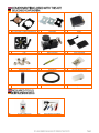
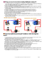
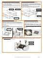
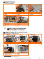
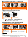
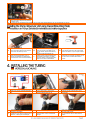
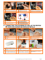
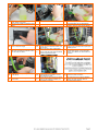
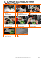
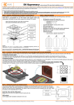
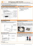
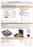
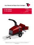
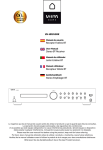
EN
D
CPU Water Block with AMD plate
CPU Wasserkühler mit AMD Montagehalterung
EN
D
CPU Backplate mechanism
CPU Backplate
EN
D
Radiator
Radiator
EN
D
Fan
Lüfter
EN
D
Pump/reservoir combo
AGB-Pumpenaufsatz
EN
D
Pump/reservoir holders
Pumpe/Tank Behälter
EN
D
Compression fittings
Klemmverschraubung
EN
D
Thermal compound - grease
Wärmeleitpaste
EN
D
CPU mounting mechanism
CPU-Kühler Montagematerial
EN
D
100mL coolant concentate
100ml Kühlmittelkonzentrat
EN
D
Tube
Schlauch
EN
D
EN
D
1L bottle of distilled water
1L Flasche mit destilliertem Wasser
EN
D
Needed hardware for installation
Benötigtes Werkzeug für die Installation
ATX Bridging Plug
ATX Überbrückungstecker
-
-
-
-
STEP 1: PREPARING THE CPU WATER BLOCK:
The water block provided with this kit is EK-Supreme LTX UNI. This water block is pre-assembled for use with modern Intel desktop socket type motherboards. By default
this water block supports the following CPU sockets:
socket LGA-775, LGA-1155/1156, LGA-1366 and LGA-2011
socket S754/939/940, AMD AMx (AM2/AM2+/AM3/AM3+) and FMx (FM1, FM2)
STEP 2: SCOPE OF DELIVERY – OVERVIEW:
You will the following mounting mechanism parts inside each EK-Supreme LTX UNI CSQ water block:
Backplate system
(2 metal plates; 1 rubber gasket)
AMD Mounting plate
Universal Mounting
screws (4 pcs)
LGA-2011 specific
Mounting screws
(4 pcs)
Springs (4 pcs)
Thumb nuts (4 pcs)
Washers (4 pcs)
STEP 3 (OPTIONAL): INSTALLING AMD MOUNTING PLATE
Note: specific instructions for AMD users!
In order to use this water cooling kit on a AMD socket motherboard it is mandatory to replace the default Intel mounting plate (also known as hold-down plate) for a AMD
one as shown below:
1) Place water block on an even surface and remove the four M4x14 DIN7991 screws attaching the top to the copper base using the enclosed 2.5mm Allen key.
2) Replace the Intel mounting plate with AMD one. You will feel the mounting plate locking into the position when placed correctly on to the top.
3) Screw in all four (4) M4x14 DIN7991 screws using the enclosed 2.5mm Allen (hex) key.
M4x14 screw
AMD mounting plate
Intel mounting plate
(default)
STEP 4: PREPARING THE CPU BACKPLATE
The enclosed rubber gasket is essential part of the backplate and mounting system and must be used every time you install this water block (except when used with LGA2011 motherboard). The rubber backplate has a partially cut inner part which needs to be removed when installed on Intel LGA-115x and LGA-1366 motherboard. The
rubber is held on four places and can be peeled away with hand. These two pieces can be reassembled later if needed.
Intel LGA-775, LGA-115x and LGA-1366 socket:
Remove the inner core of the rubber and use the outer part only.
Outer part
Intel LGA-2011 socket:
Do not use the Backplate and rubber gasket assembly at all!
AMD sockets:
Use the whole rubber backplate including the inner core.
STEP 5: INSTALLING THE WATER BLOCK
Inner core
(removable)
STEP 5a: Intel LGA-775, -1366 and AMD socket motherboard:
1) Place motherboard on an even surface with front facing down.
2) Install backplate rubber gasket - depending on your CPU platform (see
STEP 4) - and place metal backplate for Intel LGA-1366 and AMD socket to
the back of your motherboard. Align the holes on the motherboard with
holes on rubber gasket and backplate.
3) Carefully rotate motherboard assembly with front side facing up with
one hand while holding the backplate and rubber in place with the other
hand.
4) Install the rest of mounting system as per installation manual (see STEP
6)
Motherboard PCB
STEP 5b: Intel LGA-115x socket motherboard:
1) Place motherboard on an even surface with front facing down.
2) Install backplate rubber gasket - depending on your CPU platform (see STEP 4)
- and place metal backplate for Intel LGA-115x socket to the back of your
motherboard. Align the holes on the motherboard with holes on rubber gasket
and backplate. Make sure to orientate the rubber gasket to fit past the
CPU socket ILM backplate.
3) Carefully rotate motherboard assembly with front side facing up with one
hand while holding the backplate and rubber in place with the other hand.
4) Install the rest of mounting system as per installation manual (see STEP 6)
Metal backplate
Metal backplate
Rubber gasket
Motherboard PCB
Rubber gasket
figure 1: Isometric view of backplate
assembly for LGA-1366
STEP 5c: Installing the mounting system:
Intel Socket LGA-775/115x/1366 and AMD sockets:
Install the M4 thumb screws of the PreciseMount mounting system onto your
motherboard. It is mandatory to put 0.7mm plastic washer underneath each of the
M4 thumb screws. Tighten the M4 thumb screw to the metal backplate with your
hands until you reach the end of the thread. Using tools (such as pliers) is not
recommended!
Intel Socket LGA-2011:
Install four (4) specific LGA-2011 M4 thumb screws into four M4 threaded stubs on
the LGA-2011 socket integrated latch mechanism (ILM). The screws are to be
installed using no tools (i.e. pliers).
M4 thumb screw
LGA 2011 M4
thumb screw
figure 2: Isometric view of backplate assembly for LGA-115x
STEP 5d: Preparing your CPU and applying TIM:
Cleaning the CPU: Once mounting mechanism is attached install
the CPU into the socket. Wipe the CPU’s contact surface (by using
non–abrasive cloth or Q-tip, as shown on sample photo).
Applying thermal compound: EK recommends blob or line
method of applying the enclosed Gelid GC-Extreme™ thermal
compound to the CPU heatspreader (IHS) - see sample photo on
right. The quantity of about two rice grains is just about right.
There is no need to cover the whole IHS. Applying too much
thermal grease will have negative impact on the cooling
performance!
PVC washer
STEP 5e: Fastening the waterblock:
Install the waterblock on your CPU. Place an enclosed compression spring and thumb nut over each M4 thumb screw. Start fastening two thumb nuts at a
time, preferably in cross pattern and do not tighten them fully until all of them are partially screwed in. Then - using your fingers only - screw in all four
thumb nuts until you reach the end of the thread.
Thumb nut
Coiled spring
EN
Open PC case/chassis and remove stock
fans
EN
D
Gehäuse öffnen und Original-Lüfter
entfernen
D
EN
D
Place motherboard in case and screw in all
mounting screws
Mainboard im Gehäuse platzieren und mit
Schrauben fixieren.
EN
D
Mark all the holes you need to mount the
motherboard.
Mit dem Mainboard übereinstimmende
Schraubenlöcher auf dem Mainboard-Tray
markieren.
EN
Screw in the motherboard mounting standoffs
D
Distanzhülsen auf dem Mainboard-Tray
einschrauben.
Remove the blank slots needed to install the
VGA card
Slotblenden auf Höhe der Grafikkarte
entfernen.
EN
Place 2 screws, hold them with one hand and
prepare the 120mm fan
EN
While holding the screws install 120mm fan
EN
While still holding the screws install place
radiator1
D
Zwei Schrauben von Hand fixieren.
D
Lüfter von vorne über die Schrauben
schieben.
D
Radiator vor den Lüfter platzieren.
EN
D
1
Align mounting screws with threads in
radiator and screw in the screws
Nun die Schrauben mit einem
Schraubenzieher fest-ziehen.
EN
D
Screw in all 4 screws to fasten the radiator
with fan
Die restlichen beiden Schrauben ebenfalls
fixieren.
It is highly recommended you flush radiator prior its installation and use.
Es wird dringend empfohlen, dass Sie spülen Radiator vor der Installation und Nutzung.
EN
To mount the radiator on the back of the
case use EK-UNI RAD Holder.
EN
D
Verwenden Sie den EK-RAD Holder Light, um
einen Radiator an der Rückseite anzubringen.
D
EN
D
EN
D
To mount the radiator on the top (outside) of
the chassis please use EK-UNI RAD Holder
Wie im vorigen Beispiel den EK-RAD Holder
für die Installation
verwenden.
Remove the two self tapping fan screws.
Attach the 120mm Fan Mounting Plate to the
chassis using two long M4x35 screws, M4
nuts and washers.
Entfernen Sie die beiden Lüfterschrauben.
Befestigen Sie die 120mm Lüfter
Montageplatte and die Chassis mit zwei
langen M4x35 Schrauben, M4 Muttern und
Unterlegscheiben.
Use 2,5mm black plastic standoff and
M3x35mm screws to mount the radiator.
Schwarze 2,5mm Abstandhalter und
M3x35mm Schrauben verwenden, um den
Radiator am Halter zu fixieren.
EN
Install 120mm FAN in pull mode with M3x30
screws from radiator delivery.
D
Lüfter in saugender Ausrichtung am Radiator
festschrauben.
EN
Alternatively you can attach Fan Mounting
Plate directly on the chassis 120mm fan
opening using two M4x6 screws, nuts and
washers.
EN
Alternatively you can also mount the Fan
Mounting Plate directly to the radiator by using
the enclosed M3x6 screws.
D
Alternativ können Sie die Fan Montageplatte
direkt die Lüfter Öffnung mit zwei M4x6
Schrauben, Muttern und Unterlegscheiben
anschließen.
D
Schließen Sie die 120mm Lüfter Montageplatte
an die vier Pumpen Gummidämpfer mit
beiliegenden M4 Rändelschrauben an.
EN
D
2
EK-UNI RAD Holder 120 is not included within this kit. It is just shown as an example how to simplify radiator mount when space in your case becomes critical.
EK-UNI RAD Holder 120 ist nicht im Lieferumfang von Kit enthalten, kann aber separat gekauft werden. Es ist ein Beispiel dafür, die Kühlkörper Installation zu vereinfachen, wenn der Platz im PC-Gehäuse
einsgeschränkt ist.
3
This is an example of EK-Coolstream XT (240) installed on top of the PC chassis via EK-UNI RAD Holder 120. Size of radiator depends on version of kit you have in possesion.
Dies ist ein Beispiel wie man EK-Coolstream XT (240) an der Oberseite des PC-Gehäuses über EK-UNI RAD Holder 120 installiert. Die Größe der Heizkörper variiert je nach Version des gekauften Kits.
EN
D
Attach 120mm Fan Mounting Plate to the
Pump’s four rubber dampers using enclosed
M4 thumb screws
Mit beiliegenden M4 Rändelschrauben befestigen Sie die 120mm Lüfter Montageplatte an die vier Gummidämpfer der Pumpe.
EN
Secure the Class Mounting Plate to the
Pump’s four rubber dampers using enclosed
M4x4 screws and Allen key 2.5mm
D
Sichern Sie die Montageplatte an die 4
Pumpen Gummidämpfer mit beiliegenden
M4x4 Schrauben und 2.5mm Imbusschlüssel
EN
D
Examine the water loop diagram
Schauen Sie sich die Wasserkreislaufskitze
an.
EN
D
EN
D
Secure the mounting plate to your chassis at
the most suitable mounting place (i.e. chassis
bottom fan opening) using M4x6 screws,
nuts and washers. Tighten with Allen Key
2.5mm.
Befestigen Sie die Montageplatte am
Gehäuse am best geeigneten Montageort (
Ventilatoröffnung am Boden) mit M4x6
Schrauben, Muttern und Unterlegscheiben.
Ziehen Sie mit 2.5mm Imbusschlüssel.
EN
Alternatively you can drill four Ø 4.5mm holes
using electric power drill to the most suitable
place on the bottom of your computer chassis.
D
Alternativ können Sie am best geeigneten
Montageort am Unterseite von Gehäuse vier Ø
4,5 mm Löcher mit elektro Bohrmaschine
bohren.
Take a measure of required tubing length.
Von Auge nachmessen, wie lange das
benötigte Schlauch-Stück sein soll.
EN
D
Cut the tube on marked spot.
Schlauch nach der entsprechenden Länge
abschneiden.
EN
Install the compression fitting to both G1/4
openings on the radiator
EN
Install the tube on fitting
EN
Screw in the securing ring of the fitting to
secure the tube properly
D
Installieren Sie die Klemmverschraubung an
beide G1 / 4 Öffnungen am Heizkörper
D
Überwurfmutter über den Schlauch schieben
und den Schlauch auf der Anschlusstülle
anbringen.
D
Nun den Schlauch mit der Überwurfmutter
sichern.
EN
Repeat the procedure on CPU water block
EN
D
Wiederholen Sie den Vorgang auf dem CPU
Wasserblock
D
EN
Screw in the compression fitting to the
unit’s inlet (suction) port.
EN
D
Schrauben Sie die Klemmverschraubung auf
das Einheits Einlass (Saug-) Port.
D
EN
Take the cable with adaptors from the
pump delivery.
EN
D
Kabeladapter aus dem Lieferumfang
verwenden.
D
EN
Prepare the ATX bridging plug enclosed
with the kit. This gadget allows powering up
the PSU without powering up the whole
computer.
EN
D
Bereiten Sie die ATX Steckbrücke. Dieses
Gerät ermöglicht das Einschalten des PSU
ohne Einschalten des gesamten Computers.
D
Repeat the procedure on the Pump/Reservoir
Unit. Screw in the fitting on the outlet
(pressure) port.
Wiederholen Sie den Vorgang auf der
Pumpe/Behälter Einheit.
EN
Screw in the G1/4 spacer on to the
Pump/Reservoir Unit’s inlet (suction) port.
D
Schrauben Sie die G1/4 Abstandshalter an die
Pumpe/Behälter Einheits Einlass (Saug-) Port.
EN
Connect 4-pin Molex female connector to male
Molex connector of the power supply.
D
Nun den 4-Pin Molex-Stecker mit einem
Anschluss des Netzteils verbinden.
Plug in the ATX bridging plug. Make sure
nothing except the pump is plugged to the
power supply.
EN
Take about 900 mL of distilled water
Stecken Sie die ATX Steckbrücke ein. Stellen
Sie sicher das nichts anderes ( wie z.B. PCIeGrafikkarten, Festplatten,...) mit Ausnahme
der Pumpe an das Stromnetz angeschlossen
ist.
D
Für das Gemisch etwa 900mL destilliertes
Wasser verwenden.
Connect the tubing following the water
cooling loop diagram and steps in this
chapter to finalize the installation.
Verbinden Sie den Schlauch nach dem
Wasser Kühlkreislauf Diagramm in diesem
Kapitel, um die Installation abzuschließen.
Connect pumps Male 3-PIN connector to
Female Connector of the cable.
Den 3-Pin Anschluss der Pumpe mit dem
entsprechenden Anschluss des Adapters
verbinden.
EN
D
And fill in whole content (100mL) of the
water additive concentrate
Und das ganze Gehalt des Additivkonzentrat
füllen
EN
Turn on the power supply
D
Nun kann das Netzteil angeschaltet werden,
um die Pumpe zu starten.
EN
Open top of the reservoir combo
EN
Fill in the ready liquid about 2 cm from the top
D
Deckel des Ausgleichsbehälters entfernen.
D
Ausgleichsbehälter mit der Kühlflüssigkeit
auffüllen. (Achtung: Nicht randvoll auffüllen!)
EN
Alternately turn off and on (cycle) power
supply in few second intervals to speed up air
bleeding process.
D
Ist der gesamte Kreislauf befüllt, kann die
Pumpe einige Male ein- und ausgeschaltet
werden, um Luftblasen aus dem Kreislauf zu
entfernen.
EN
Leave your PC case for 24 hour leak tes, to
ensure the system is leak free.
D
Nun sollte die Pumpe 24 Stunden betrieben
werden, um sicher zu stellen, dass der
Kreislauf komplett dicht ist.
EN
D
EN
Close the reservoir by screwing in the top
acetal endcap.
EN
D
Deckel wieder auf dem Ausgleichsbehälter
aufschrauben.
D
Fill up the liquid while the pump is running
and stop when the water level reaches 2 cm
under the edge
Während die Pumpe läuft, Kühlflüssigkeit
nachfüllen. Sollte sich der AGB komplett
entleeren, kann die Pumpe über das Netzteil
nochmals ausgeschaltet werden.
Shake and tip the PC case to remove any air
possibly trapped in the radiator. You may
need to add more coolant.
Nun kann der PC etwas geneigt und gedreht
werden, um die restlichen Luftblasen aus
dem Kreislauf zu entfernen.
EN
Cover all exposed hardware with a towel or
paper towels
EN
Take a container and hold the pump
reservoir combo above it.
EN
Unscrew the G1/4 plug on the Reservoir
combo or slowly remove one of the tube from
fitting.
D
Alle Hardwareteile mit tüchern oder
Haushalts-Papier abdecken.
D
Einen Auffangbehälter verwenden und die
Pumpe mit dem Ausgleichbehälter darüber
halten.
D
G1/4" Verschlusskappe entfernen.
EN
D
EN
Let the water run away into the container
EN
Unplug the tubes connecting to pump
reservoir combo, remove the pump
D
Das Wasser aus dem AGB in den
Auffangbehälter fliessen lassen.
D
Die Beiden Schläuche vor und nach dem
Pumpen-AGB Kombi entfernen.
EN
Dry the tubes and pump with paper towel
D
Komponenten mit den Tüchern trocken
wischen.
EN
D
Keep the tubes over the towel to prevent
water to spill over the hardware
Die Schläuche über dem Auffangbehälter
oder den Tüchern halten.
Keep one tube in the container and gently
blow into the other tube to additionally drain
the system
In das eine Schlauchende pusten, um den
Kreislauf weiter zu entleeren.