1
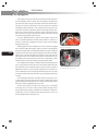
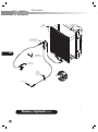
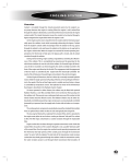
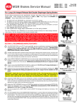
cooling
Overview
Coolant is circulated through the closed pressurized system by the engine’s water pump whenever the engine is running. When the engine is cold, coolant flow
through the radiator is blocked by a conventional thermostat mounted at the engine
coolant outlet. The closed thermostat causes the coolant to be directed through a
bypass integral to the engine block when the engine is cold.
As the engine warms, heat is transferred to the coolant and the thermostat gradually opens the radiator circuit while increasingly obstructing the bypass. Coolant
from the engine’s coolant outlet increasingly enters the radiator at the top, passes
through the radiator’s coils and leaves the radiator at the bottom on its way back to
the engine coolant inlet. When the engine has reached full normal operating temperatature, the thermostat is fully open, the bypass path is closed, and all coolant
circulates through the radiator.
During normal running, engine cooling is regulated by controlling the effectiveness of the radiator. This is accomplished by powering and de-powering the fan
which draws ambient air over the coils of the radiator. On Forward Engine All Americans, the fan is mounted to an electromagnetic fan clutch assembly mounted to the
front of the engine and driven by the fan belt. The engagement and disengagement
of the fan clutch is controlled by the engine ECM. The electrically-controlled fan
clutch of the All American Forward Engine is described in the electrical chapter.
On buses operated in colder climates, the radiator may be fitted with optional
Radiator Shutters, a vane-like assembly which serves to block air from passing over
the radiator coils. This prevents over-cooling and aids warm-up of the coolant so that
interior heaters become effective sooner. The Radiator Shutters may be either hydraulically controlled (powered by engine oil pressure), or pneumatically controlled
(powered by air pressure from the supply tank of units with air brakes or air suspension).
The cooling system components are plumbed using either standard black rubber
hoses or optional hoses which are blue in color and typically have longer life.
The bus may be fitted with an optional Perry Coolant Filter, which is attached to
the engine water jacket at two locations, creating an alternate “side path” for coolant
to flow. The filter traps contaminates as coolant circulates through the replaceable
filter.
Engine coolant also circulates through a separate transmission cooler. Unike the
coolant filter, this portion of the coolant’s flowpath is not a parallel “alternate path”
of the coolant flow. Once the engine has reached normal operating temperature and
the thermostat has fully opened, all the coolant passes through the transmission
cooler, “in series” with the radiator. The inlet side of the transmission cooler receives
coolant that has already passed through the radiator. Inside the transmission cooler,
the water circulates around a coil through which transmission fluid circulates. At
normal operating temperatures, the engine coolant is significiantly cooler than the
the transmission fluid and thereby serves to cool the transmission fluid. In extremely
cold climates, during engine warm-up, the warming engine coolant helps bring the
transmission fluid up to sufficient temperature for the transmission to operate.
553
L
SERVICE MANUAL
554
L
Heated engine coolant also provides the heat for the bus’s interior heating units.
The heater plumbing circuit is a “parallel” circuit which begins at the high pressure
side of the engine water jacket, cycles through the various heater elements and returns by way of an inlet to the transmission cooler. There it rejoins the coolant bath
circulating through the transmission cooler, and thereby finds its way back to the
engine inlet. A cut-off valve is provided at engine heater outlet pipe and at the transmission cooler’s heater circuit inlet. This allows the heating circuit to be blocked at
both ends when servicing the cooling system or when it is desireable to prevent
heaters from warming up during summer months.
The heater supply tubing from the engine leads to the Driver’s remote heater
valve, an electrically-controlled valve which enables the Driver to control the effectiveness of all heaters by regulating the amount of engine coolant circulating
through the heater circuit.
Depending upon the heaters configuration, the heater circuit may be equipped
with an optional auxilliary water pump to help force-circulate coolant through the
heaters. The auxilliary pump on Forward Engine All Americans resides in a dedicated
housing mounted to the floor along the heater piping. The inlet side of the auxilliary
pump receives coolant from the high pressure side of the engine water jacket. The
outlet side leads to the series of heaters and then returns via the transmission cooler
as described above. Thus, the transmission cooler receives coolant that has cooled by
transferring its heat to the heaters and/or by passage through the radiator.
The cooling filler neck is integral to a deaeration tank located at the highest point
of the cooling system flow circuits. Tubes lead to the deaeration tank from the tops
of the radiator, the engine, and the transmission cooler. This provides a path for air
bubbles in the circuits to rise to the deaeration tank. When pressure inside the system rises sufficiently to overcome the spring of the filler neck’s pressure cap, air that
has collected in the top of the deaeration tank escapes, reducing the system pressure
to normal.
On Forward Engine All American’s the radiator must be removed to gain access
to certain service components on the front of the engine. To facilitate this, an option
popularly installed on Forward Engine buses is a swing out radiator, which provides
limited access without requiring draining of the coolant.
The three main symptoms of trouble in the cooling system are overheating,
overcooling, and loss of coolant. A cooling system should first be diagnosed by a
thorough visual inspection. Debris accumulation in the radiator fins or bent fins restricting airflow can cause overheating. If visual inspection reveals no cause, tools
and test equipment will be needed to proceed.
Forward Engine heater supply cutoff valve. Accessible from
interior engine compartment hood.
Forward Engine heater return cutoff valve. Accessible from
under the bus, forward of the entrance stepwell.
cooling
When excessively high operating temperature is observed, first check for proper
fluid level at the sight glass of the deaeration tank. If the fluid level is low and cannot
be maintained without constant refill, inspect for leaks at pipe and hose connections.
Also look for damaged hoses due to heat or chaffing from incorrect routing. Remember that the heater system is a potential area for leaks. The heating system can be
isolated by closing the gate valves at the engine’s heater outlet and the transmission
cooler’s inlet.
In the case of overheating, the next step is to verify the proper operation of the
thermostats. Refer to the appropriate engine manufacturer’s service publication for
instructions on the removal and testing of the thermostats.
[Warning] The engine, coolant, and transmission fluid may be very hot
(possibly above the boiling point at atmospheric pressure). Allow the system to
cool completely before working on it. Engine coolant use and disposal is governed by environmental regulations. Read carefully and abide by the warnings
and guidelines on the coolant label.
555
L
SERVICE MANUAL
Driver Side
Heater
Remote
Heater Valve
Passenger Compartment Heaters
556
Auxiliary Pump
Optional pump helps
circulate engine coolant
through heaters.
May be installed
at various locations,
depending upon
heater configuration.
Right Front Heater
L
cooling
Coolant Filter
Optional filter unit mounted in
an alternate parallel path for
coolant to flow. Shut off valves
provided to isolate the filter
for element change.
Fan Clutch / Motor
is controlled by
the engine ECM.
On A3FE, electromagnetic Fan Clutch
cycles on and off.
On A3RE, hydraulic motor varies in speed.
Shutters
open and close
according to temperature
measured at
both the water jacket
and the intake air.
557
Transmission Cooler
A a coil through which
transmission fluid circulates is bathed
in engine coolant to carry away heat.
Also serves as the return point of coolant
circulating through heaters.
Heater
Cut-Off Valves
L
SERVICE MANUAL
Torque Specifications
16 Capscrews
27 Nuts
41 Nuts
44 Nuts
All Spring Loaded and
Constant Torque Clamps
41
To
Engine
Vent
558
To 3/4” port
on water inlet
41
To Air Intake
elbow on
left side of
engine
To Engine
water outlet
To Turbo
Compressor
outlet
Cooling System Diagram
L
20-25 lbs-ft
80 lbs-ft
18-20 lbs-ft
30-32 lbs-ft
5 lbs-ft
cooling
27
44
16
559
0000677,8a
Hi Torque Transmission
To Engine
water inlet
Standard Low Torque
Transmission
L
SERVICE MANUAL
About Coolant
560
As emission and performance regulations become more stringent, the normal operation temerature range for turbocharged diesel engines increases. One of the consequences is that careful maintenance of the cooling system becomes increasingly
critical in prolonging the life of the engine. At higher temperatures, relatively minor
imbalances or impurities in the coolant can dramatially increase the potential for
corrosion. Establish a disciplined and consistent regimine for monitoring and testing
the coolant in your Blue Bird school buses. Keep accurate records, use only coolants
recommended by the engine manufacturer. Change coolant within its specification
lifetime and never mix different types of coolant.
Periodic testing and maintenance of the coolant should be performed in accordance to the engine manufacturer’s specifications. Testing and maintenance procecures differ between standard-life and extended-life coolants. Locally available test
strips may be used to test standard-life coolants. However, such test strips are not appropriate for long-life coolants; therefore long-life or extended-life coolants must be
sample tested at qualified cooant laboratories. Because specification, recommendation, and terminologies differ among engine manufacturers, Blue Bird advises stictly
adhering to the coolant maintenance specifications of the engine manufacturer.
Carefully following the engine manufacturer’s recommendations is the surest way to
maintain compliance with engine warranties.
Beginning in January of 2007, Blue Bird implemented a program to simplify the
coolant types installed at the factory.
Standard Equipment Coolant
Cummins Fleetguard ES Compleat 50/50 premix (blue in color) is installed as standard equipment with Cummins.
This coolant meets all specifications and requirements for extended-life coolant
and is to be considered standard-life coolant when installed in Cummins engines.
Optional Extended Life Coolant
Cummins Fleetguard ES Optimax 60/40 premix (red in color) is installed in bus products equipped with Cummins engines when purchased with an option for extendedlife coolant.
Coolant Decals
On all of the above-listed bus models, Blue Bird installs a decal stating:
• The type of coolant installed at the factory.
• The coolant manufacturer’s part number for one gallon quantity, suitable for
regular top-off and refill.
• The coolant manufacturer’s part number for one gallon quantity of the concentrate version of the installed coolant, suitable for formulating stronger glycol mixture ratio.
Blue Bird also installs a second decal containing radiator warnings. Both decals
are mounted near the coolant fill neck.
L
Note: If you wish to convert from standard life coolant to Fleetguard ES Optimax extended life coolant, follow the
guidelines set forth in the Fleetguard
Maintenance Bulletin, MB1/04-1 at
www.cumminsfiltration.com/pdfs/product_lit/americas_brochures/MB1-04-1.
pdf.
cooling
Coolant Maintenance
Blue Bird advises strictly abiding by the following policy for all coolant maintenance
for the life of the vehicle.
Never Mix Coolant Types
Routine coolant addition (top-off) must match the installed coolant type and brand.
Do not mix coolants of different colors, types, or brands in the same engine.
Strictly Follow The Engine Manufacturer’s Specifications
Each engine manufacturer publishes its own specific requirements for testing and
maintaining coolant in their respective engines. Blue Bird recommends strictly abiding by the engine manufacturer’s testing and maintenance schedules and draining,
flushing, refilling procedures to maintain compliance with the engine warranty requirements. Blue Bird recommends that you maintain accurate vehicle-specific service records of all coolant system maintenance procedures performed.
For Cummins engines using Fleetguard ES coolants, send coolant samples to
Fleetguard for Monitor C testing, as specified in the Cummins Operator’s Manual.
Label sample as Extended-Life coolant.
Note: For more information on coolant
testing tools see: www.cumminsfiltration.com/pdfs/product_lit/americas_
brochures/LT15068.pdf.
561
Always Mix Concentrate With Premix Coolant, Not Water
If concentrated coolant is added in order to raise the glycol ratio, use only the concentrate version of the same premix coolant type and brand as installed. Do not mix
the concentrate with water. Instead, mix the concentrate with the premix version of
the same coolant.
Only Add Tap Water In Emergency Situations
A regularly-scheduled bus inspection and maintenance program should be followed
to prevent coolant losses due to damaged or worn hoses, loose clamps, etc.
If coolant is lost while the bus is in use, and roadside emergency measures are
called for, replenish the coolant with the same premix type and brand if possible. If
the proper coolant is not available, and water must be used, use only de-ionized water if possible. Ordinary tap water should only be used if proper coolant or de-ionized
water are not available.
Whenever tap water alone has been added, the bus should be taken to a service
facility and the entire cooling system should be completely drained, flushed, and
refilled with premix coolant.
L
SERVICE MANUAL
FACTORY INSTALLED COOLANTS
Cummins, Fleetguard ES Compleat
Blue in color. Standard equipment coolant in all D3FE, D3RE, BBCV.
Considered standard-life coolant in Cummins engines.
Concentrate version may be mixed with the pre-mix version to lower freezing point.
AVAILABILITY
50/50 Premix
1 Gallon Container
2 1/2 Gallon Container
55 Gallon Drum
330 Gallon Tote
Concentrate
1 Gallon Container
562
Cummins, Fleetguard ES Optimax
Red in color. Optional coolant in D3FE, D3RE, BBCV, with Cummins engines.
Qualifies as extended-life coolant in Cummins engines.
Blue Bird installs 60/40 premix, which is not available in one gallon containers, but is available in larger containers (listed).
The 50/50 premix may be mixed with the concentrate version per Fleetguard’s instructions to achieve 60/40 ratio.
Concentrate version may be mixed with the pre-mix version to lower freezing point.
AVAILABILITY
50/50 Premix
1 Gallon Container
60/40 Premix
55 Gallon Drum
275 Gallon Tote
Concentrate
1 Gallon Container
L
cooling
Radiator Shutters
Your bus may be equipped with Radiator Shutters, a popular option on both Forward
Engine and Rear Engine All American buses operated in colder climates. Shutters
restrict ambient air passing through the radiator and over the engine, and thereby
shorten warm-up time for the engine and passenger compartment heaters.
The Kysor Radiator Shutters unit is a window blind-like assembly of adjustable
louvers mounted on the fan-side of the radiator. The shutters are spring-loaded in
a normally-open position. On buses equipped with air brakes, the shutter mechanism is closed at certain temperatures by an air cylinder, and on buses with hydraulic
brakes, by an hydraulic actuator.
Unlike the radiator fan, shutters are not controlled by the engine ECU, but by their
own independent circuit. Two temperature sensors—one mounted in the engine
coolant circuit and the other in the intake tract of the Charge Air Cooler system—
are wired in the Radiator Shutters control circuit. Both sensors are normally closed.
When ignition is on, current passes through both sensors, and energizing the Shutter
control solenoid to close the shutters. As the engine warms, one or both of the two
sensors create an open in the circuit, de-energizing the shutter control solenoid and
allowing the leuver vanes to open the shutters.
Air-powered shutter solenoids receive actuation air from a line leading directly
to the supply (wet) air tank. When the solenoid opens, the air which was closing the
shutters is expelled through the solenoid’s exhaust port.
Hydraulically-powered shutter solenoids receive engine oil from a line leading
from an oil supply port on the left side of the engine. When the solenoid opens, the
oil which was closing the shutters is returned to the engine sump through the solenoid’s drain line.
Shutters should be inspected regularly and kept free of obstructing debris. The
pivot points of the leuvers and their linkages should be lubricated periodically with a
light spray lubricant such as WD40 or a graphite spray.
563
L
SERVICE MANUAL
Lubricate
upper and lower
pivot points and track.
IN
T
OU
DRAIN
Shutter solenoid
mounted to lower left side of
Engine closeout panel.
564
(ISB only)
Cummins ISB:
Install on Left side
of air intake manifold elbow.
To oil supply port
onleft side of engine.
To engine oil pan.
Shutters, Hydraulic Optional
L
Turbo Side
Of Valve Cover
Cummins ISB
00002013s
Mounts to
threaded boss
just above
oil pan flange
cooling
Lubricate upper and lower
pivot points and track.
Shutter solenoid mounted to
lower left side of
engine closeout panel.
IN
UT
O
565
(ISB only)
Cummins ISB:
Install on left side of
air intake manifold elbow.
Mount bracket to
threaded boss
just above oil pan flange.
Turbo Side
Of Valve Cover
Cummins ISB
00002015j
To Accessory Port
at Wet Tank
Shutters, Air Optional
L
SERVICE MANUAL
Radiator
On both All American Forward Engine and All American Rear Engine buses, the radiator is pre-assembled to a similarly-constructed Charge AIr Cooler; however, other
than being assembled and mounted as a combined “cooling pack”, the two units
serve two separate circuits and do not directly interact. While the radiator serves
to remove heat from the circulating engine coolant, the Charge Air Cooler removes
heat from the engine intake air. Both perform their functions by passing ambient air
drawn by the radiator fan across tubing coils which contain coolant (in the radiator)
or filtered intake air (in the Charge Air Cooler). The thin corregated fins of each unit
conduct heat from the internal coils and thereby disperses it across a broad surface
area, allowing it to be carried away by the flow of air.
See the Intake chapter for a more complete functional description of the Charge
Air Cooler system. In the descriptions below, references to “the radiator assembly” refer to the combined cooling pack, since the radiator and CAC are handled as a unit. If
the bus is equipped with optional radiator shutters, the shutters unit is also attached
to the radiator, and all three components are removed and installed together.
566
Swing Out Radiator
On Forward Engine All Americans, servicing components at the front of the engine
and behind the radiator assembly, such as pulleys, water pump, fan belt, fan clutch,
air conditioner compressors, or radiator shutters may require removal of the radiator.
A popular option on Forward Engine units, therefore, is a special set of parts which
allow the radiator to be pivoted slightly without disconnecting coolant hoses and
draining coolant. For additional information on the swing out radiator see SwingOut Radiator in the Chassis Frame section of the manual.
The actual mounting of the radiator unit itself is very similar between the standard installation and that of the swing out radiator option. The components which
differ are:
• Longer coolant hoses to allow the necessary flexibility at the radiator.
• A special set of bumper brackets which allow the bumper to pivot downward
without complete removal.
Radiator Removal
1. Completely secure the bus against accidental movement. Remove the ignition key. Chock all wheels. Disconnect the positive battery terminals (or turn
off the master power switch if so equipped.)
2. Pivot or remove the front bumper; see Bumpers in the Chassis Frame section of this manual.
L
cooling
3. Open the front grille panel.
4. Inside the bus, remove the engine cover; see Engine Access in the Power
Drivetrain section of this manual.
4.1 Remove the cup holder and PA system mic.
4.2 Pull and release the rubber handle latch anchor located at the lower
front wall of the engine hood assembly.
4.3 Open the hood and locate four latches on the inner wall perimeter
of the hood assembly. Releasing these latches will then allow entire
hood assembly to be removed for mechanics access.
5.Loosen all charge air cooler tubes.
6. Drain the coolant:
6.1 Position a clean receptacle under the petcock drain at the bottom of
the radiator. Remove the filler pressure cap. Open the petcock drain.
(Tip: After draining at the petcock stops, it is often helpful to also loosen the lower radiator hose clamp and insert a screwdriver between
the hose and the radiator. This allows additional coolant to drain from
the dip in the lower hose.)
6.2 Disconnect the radiator hoses: Loosen the deaeration vent hose clamp
at the top of the radiator and push the vent hose end off the radiator.
Loosen the upper and lower radiator hose clamps and push the hoses
back enough to ensure they are unstuck and will slip off when the
radiator is removed.
567
12. The radiator assembly is mounted on four rubber-cushioned mounts, two
on each side. Completely remove all four mounting bolts, eight washers, and
four nuts. With an assistant, lift the radiator forward and away from the bus.
Reassembly
Having the radiator removed or hinged provides access to engine front components.
After the service procedures are complete, reinstall the radiator, bumper, rock guard,
CAC tubes and grille in reverse order of the removal proceure outline. If the coolant
has been drained into a clean recepticle, and if it is still within its service life, it may be
reinstalled. After refilling, bleed the heater system to remove trapped air and ensure
that the coolant level is topped-off to the proper level.
L
SERVICE MANUAL
Cooling System Drain, Flush & Refill
The following is a general procedure for complete coolant change (drain, flush, refill).
Blue Bird recommends that an authorized Cummins dealer/distributor perform this
flush and fill. If there are differences between the information in this procedure and
the engine manufacturer’s Operator’s or Maintenance Manuals, follow the engine
manufacturer’s instruction.
1. Drain the cooling system:
1.1 Park bus on a level surface, apply parking brake, turn off engine, remove ignition key and chock wheels.
1.2 Allow the engine to cool. Then remove the radiator cap. Locate and
open both heater hose cut-off valves. Open all heater control valves
fully. Removal of the thermostat may assist in draining, flushing, rinsing and refilling process. Follow engine manufacturers’ recommendations on thermostat removal and installation.
568
L
[Warning] Coolant released under pressure can cause serious burns. Remove filler cap only when cool enough to touch with bare hands. Slowly loosen
cap to first stop to vent pressure before fully removing. Engine coolant is toxic
and is an eye and skin irritant. Protective gear should be worn when working
with coolant. Allow the system to cool before draining and flushing. Engine
coolant is a threat to the environment. Use suitable containers for disposal. All
applicable federal, state, and local laws must be observed when disposing of
engine coolant.
1.3 Place a drain pan under the radiator drain and open the drain petcock.
Drain and discard the coolant from the cooling system following all
applicable federal, state, and local laws governing disposal of engine
coolant. Be sure that all the heater valves are open in order to completely drain the engine, heaters, coolers, hose, etc.
1.4 After system has drained, disconnect both the pressure and return
heater hoses. Using a shop air hose set at a maximum of 15 PSI, blow
air into the heater hoses to blow the remaining coolant from the heater system.
1.5 Open the lowest coolant drain port or plug from the engine to drain
any remaining coolant from the engine.
1.6 Close all drains, reconnect heater hoses, and reinstall all plugs that
have been opened or removed.
1.7 If the system has a coolant filter, close the valves to the filter and remove the filter element.
cooling
1.8 On All American Forward Engine Only: If the system has any material collected on the cap, neck or deaeration tank, remove and replace
the radiator cap (00065628), and plastic deaeration tank (00126417).
If the system has discolored coolant, inspect the cap, neck and deaeration tank for accumulation of foreign material or staining. If stained,
clean the components. If the stain cannot be removed, replace the
components. If the coolant is not discolored, and there is no accumulation on theses components, do not replace these components.
1.9 Reconnect all hoses that were disconnected while replacing components. Check all hose connections and clamps.
1.10 If the thermostat has been removed in an earlier step, reinstall thermostats following engine manufacturer’s procedures.
2. Clean the Cooling System. Follow the engine manufacturer’s instructions for
chemically cleaning the entire cooling system.
On Cummins engines: If sludge or oil is evident, Use Fleetguard Restore. For
scale or heavy metal deposits, use Fleetguard Restore Plus (+).
2.1 After the engine has been stopped and the cooling system has cooled,
drain the cleaner from the entire system following the steps describe
in the initial drain including blowing the system with 15 PSI (max) of
shop air.
2.2 Close all drains and reconnect all hoses that have been removed.
2.3 Fill the system with fresh water and run for minimum of 30 minutes on
high idle with heater pumps on and all heater valves open.
2.4 After the 30 minute (minimum) run, stop the engine and allow it to
cool. Then drain the water from the entire system following the steps
describe in the initial drain, including blowing the system with 15 PSI
(max) of shop air.
2.5 With the hoses disconnected and the drain valves open, run fresh
water through the heater system, radiator, transmission cooler and
engine until the water is clear.
2.6 Repeat steps 2.2 thru 2.5 as many times as required to ensure that the
system is clean and the chemicals are completely removed.
569
[caution] After having used cooling system cleaners, be sure the systems
are flushed 3–5 times to remove all cleaner from the system. If cleaner is not
completely removed, ammonia salts will be left from the cleaner and severe
copper corrosion can occur.
L
SERVICE MANUAL
3. If the bus is equipped with an optional coolant filter, check the filter head,
clean filter head and lines as required to remove all of the old coolant and
any residue. Install a new coolant filter element.
4. Refill the cooling system with coolant recommended by the engine manufacturer. Read the About Coolant section of this chapter thoroughly for information about the coolants installed at the Blue Bird factory, and for Blue Bird
recommendations. Blue Bird recommends using only pre-mixed coolant, or
mixing of premixed coolant with concentrate of the same type and brand (as
opposed to mixing concentate with water) to raise the glycol ratio above that
of the premixed coolant. Blue Bird recommends always topping-off coolant
with the same pre-mixed coolant as is installed, rather than topping off with
water. If water is used for top-off, use only deionized water. Never add tap
water to the cooling system unless absolutely necessary in roadside emergency situations. Never mix coolants of different color, type, or brand. Keep
accurate records of all coolant changes and maintenance.
570
5. Bleed Air From the Cooling and Heater System:
5.1 Fully open the pressure-side heater hose cut-off valve. Fully close the
return-side heater cut-off valve (located near the transmission cooler).
5.2 In the Driver’s area, open all heater temperature controls to their full
on position, and turn on all heater pumps. The number of heater
controls, and the presence of heater pumps depends upon optional
equipment purchased on the bus.
5.3 With the engine stopped and a cool engine, remove the radiator cap.
5.4 On All American buses, locate the ¼” bleeder tube which is located
near the deaeration tank. The bleeder tube originates from a low point
of the cooling system, where the return heater hose returns coolant to
the transmission cooler; and runs to a location near the deaeration
tank.
L
On All American Forward Engine buses: Open the front grille panel.
The bleeder tube is tucked horizontally along the top of the radiator.
Pull out the bleeder hose and insert its free end into the open filler
neck of the deaeration tank. Then open the in-line bleed valve fully.
During bleeding, overflow coolant will be returned directly to the deaeration tank.
cooling
5.5 Start engine and operate at 1800 to 2000 rpm. Watching the coolant
temperature gauge, ensure the engine reaches 180-190 degrees, the
temperature at which the engine’s thermostat normally fully opens.
5.6 Operate the engine with the bleeder valve open until all air has been
purged from the system. During this time, monitor the level of coolant
in the deaeration tank. As air trapped in the system escapes, the coolant level will occasionally rise and drop. Top-off the coolant level with
pre-mixed coolant whenever it drops below the full level mark.
5.7 Air has been fully purged from the system when the coolant level no
longer fluctuates, and the stream of coolant from the bleeder hose is
constant. This may take 15-30 minutes.
5.8 After the air has been purged and solid stream is present, allow the
engine to return to idle to cool down gradually. Close the bleeder
valve and store the bleeder line in its original position.
5.9 Install the radiator cap.
5.10 Operate the engine until the thermostat opens. Then stop the engine
and let it cool for 15-30 minutes. Check the entire cooling and heating system for leaks. Recheck coolant levels and top off with the same
premixed coolant as is installed.
5.11 Obtain a coolant sample from the radiator drain petcock, and test
the glycol level with a refractometer to ensure the glycol level is 50%
minimum. If the glycol level is less than 50%, drain the appropriate
amount of coolant and add concentrate per the engine manufacturer’s instructions for increasing glycol percentage to correct level.
5.12 Pressure test the cooling system for leaks. If no leaks are found, the
bus may be returned to normal service.
571
L
SERVICE MANUAL
Fan Clutch
572
L
During normal running, engine temperature is regulated by controlling the cooling
effectiveness of the radiator. This is accomplished by powering and de-powering the
fan which draws ambient air over the coils of the radiator.
On All American Forward Engine buses, the fan is mounted to an electromagnetic clutch mechanism. The outer housing drum of the fan clutch is a pully driven by
the fan belt, and rotates whenever the engine is running. The fan blade assembly is
mounted to the inner rotor of the fan clutch. An electromagnetic mechanism within
the fan clutch assembly engages/disengages the inner rotor with the outer drum,
and also serves to “cushion” the initial shock of engagement.
The engagement and disengagement of the fan clutch is controlled by the engine ECU. The ECU electronically monitors a signal it receives from a temperature
sensor mounted near the engine coolant outlet. When the temperature signal reaches a pre-defined value, the ECU provides 12V current to engergize the fan clutch.
The clutch engages and the fan blades are driven at engine speed, drawing more air
through the radiator.
When the fan clutch is de-energized, the collapsing magnetic field momentarily
induces a current with reversed polarity in the stator. The electrical connector of the
fan clutch contains a diode which provides the induced current a low-resistance path
to ground, to protect other circuits from being affected.