1
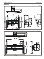
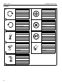
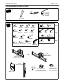
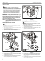
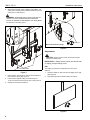
INSTALLATION INSTRUCTIONS
RLC1
RMC1
(Shown installed to
UL Listed Chief CPA column
as example only)
(Shown installed to
1-1/2" NPT column
as example only)
Single Flat Panel Ceiling Mounts
Spanish Product Description
German Product Description
Portuguese Product Description
Italian Product Description
Dutch Product Description
French Product Description
RMC1 / RLC1
RMC1 / RLC1
Installation Instructions
DISCLAIMER
Milestone AV Technologies and its affiliated corporations and
subsidiaries (collectively "Milestone"), intend to make this
manual accurate and complete. However, Milestone makes no
claim that the information contained herein covers all details,
conditions or variations, nor does it provide for every possible
contingency in connection with the installation or use of this
product. The information contained in this document is subject
to change without notice or obligation of any kind. Milestone
makes no representation of warranty, expressed or implied,
regarding the information contained herein. Milestone assumes
no responsibility for accuracy, completeness or sufficiency of
the information contained in this document.
Chief® is a registered trademark of Milestone AV Technologies.
All rights reserved.
WARNING: Use this mounting system only for its intended
use as described in these instructions. Do not use
attachments not recommended by the manufacturer.
WARNING: Never operate this mounting system if it is
damaged. Return the mounting system to a service center for
examination and repair.
WARNING: Do not use this product outdoors.
IMPORTANT ! : The RMC1 and RLC1 mounts are
designed to be mounted to a 1-1/2" NPT or NPSM
following ANSI/ASME B1.20.1 (Schedule 40, 0.154"
minimum thickness steel or aluminum-ASTM B221)
threaded extension column (not included); OR a UL
Listed Chief CPA extension column (not included).
IMPORTANT SAFETY INSTRUCTIONS
WARNING: A WARNING alerts you to the possibility of
serious injury or death if you do not follow the instructions.
CAUTION: A CAUTION alerts you to the possibility of
damage or destruction of equipment if you do not follow the
corresponding instructions.
WARNING: Failure to read, thoroughly understand, and
follow all instructions can result in serious personal injury,
damage to equipment, or voiding of factory warranty! It is the
installer’s responsibility to make sure all components are
properly assembled and installed using the instructions
provided.
WARNING: Failure to provide adequate structural strength
for this component can result in serious personal injury or
damage to equipment! It is the installer’s responsibility to
make sure the structure to which this component is attached
can support five times the combined weight of all equipment.
Reinforce the structure as required before installing the
component.
WARNING: Exceeding the weight capacity can result in
serious personal injury or damage to equipment! It is the
installer’s responsibility to make sure the combined weight of
all components located between the mount up to (and
including) the display does not exceed 125 lbs (56.7 kg).
2
--SAVE THESE INSTRUCTIONS--
Installation Instructions
RMC1 / RLC1
DIMENSIONS
RMC1
18.00
457.2
MAX MOUNTING PATTERN
7.87
[200]
MIN MOUNTING PATTERN
RLC1
24.00
609.6
MAX MOUNTING PATTERN
7.87
[200]
MIN MOUNTING PATTERN
15.75
400.0
MAX MOUNTING
PATTERN
3
RMC1 / RLC1
Installation Instructions
LEGEND
Tighten Fastener
Adjust
Apretar elemento de fijación
Ajustar
Befestigungsteil festziehen
Einstellen
Apertar fixador
Ajustar
Serrare il fissaggio
Regolare
Bevestiging vastdraaien
Afstellen
Serrez les fixations
Ajuster
Loosen Fastener
Remove
Aflojar elemento de fijación
Quitar
Befestigungsteil lösen
Entfernen
Desapertar fixador
Remover
Allentare il fissaggio
Rimuovere
Bevestiging losdraaien
Verwijderen
Desserrez les fixations
Retirez
Phillips Screwdriver
Optional
Destornillador Phillips
Opcional
Kreuzschlitzschraubendreher
Optional
Chave de fendas Phillips
Opcional
Cacciavite a stella
Opzionale
Kruiskopschroevendraaier
Optie
Tournevis à pointe cruciforme
En option
Open-Ended Wrench
By Hand
Llave de boca
A mano
Gabelschlüssel
Von Hand
Chave de bocas
Com a mão
Chiave a punte aperte
A mano
Steeksleutel
Met de hand
Clé à fourche
À la main
Hex-Head Wrench
Llave de cabeza hexagonal
Sechskantschlüssel
Chave de cabeça sextavada
Chiave esagonale
Zeskantsleutel
Clé à tête hexagonale
4
Installation Instructions
RMC1 / RLC1
TOOLS REQUIRED FOR INSTALLATION
3/32" (included)
1/8" (included)
5/32" (included)
M5 (included)
#2
1/2" or 13mm
PARTS
[Interface Bracket Hardware Kit]
A (8)
M4x16mm
E (6)
M5x20mm
I (6)
M8x20mm
B (6)
M4x20mm
F (6)
M5x25mm
C (6)
M4x25mm
G (6)
M6x16mm
R (2)
5/16"
Q (2)
5/16" x 1"
D (6)
M5x16mm
S (1)
3/32"
H (6)
M6x25mm
J (6)
M8x30mm
L (8)
M (8)
.750x.323x.250 .750x.344x.500
U (1)
5/32"
T (1)
1/8"
V (1)
10-24 x 1/4"
Bag A
Bag B
W (3)
5/16" x 3/4"
K (4)
M8x50mm
N (8)
[Universal
washer]
P (1)
M5
[In bag
labeled "N"]
X (2)
10-24 x 1/2"
Y (2)
10-24
Bag C
Z (1)
[Ceiling mount
assembly - RLC1]
OR
Z (1)
[Ceiling mount
assembly - RMC1]
BB (2)
[Interface bracket]
CC (2)
10-24 x 5/8"
AA (1)
[Back cover]
DD (1)
[Bottom stop collar]
(Used with UL Listed
Chief CPA extension column)
EE (1)
[Bottom coupling]
(Used with 1-1/2"
NPT column system)
5
RMC1 / RLC1
Installation Instructions
INSTALLATION
WARNING: FAILURE TO PROVIDE ADEQUATE
(W) x 2
4
STRUCTURAL STRENGTH FOR THIS COMPONENT CAN
RESULT IN SERIOUS PERSONAL INJURY OR DAMAGE
TO EQUIPMENT! It is the installer’s responsibility to make
sure the structure to which this component is attached can
support five times the combined weight of all equipment.
Reinforce the structure as required before installing the
component.
IMPORTANT ! : These instructions assume that a 1-1/2"
NPT or NPSM following ANSI/ASME B1.20.1 (Schedule
40, 0.154" minimum thickness steel or aluminum-ASTM
B221) threaded extension column (not included); or a UL
Listed Chief CPA extension column (not included) has
been properly installed and is in place.
Figure 2
NOTE: Proceed to Attaching Mount to NPT Column section
or Attaching Mount to Chief CPA Column section, as
appropriate.
Attaching Mount to Chief CPA Column
Attaching Mount to NPT Column
CAUTION: WATCH FOR PINCH POINTS! Do not place
fingers between moveable parts.
CAUTION: WATCH FOR PINCH POINTS! Do not place
fingers between moveable parts.
1.
Slide ceiling mount (Z) up from below onto installed column
(not included). (See Figure 1)
2.
Thread bottom coupling (EE) onto installed column until
tight, with a minimum of four threads engaged.
1.
Slide ceiling mount (Z) up from below onto installed column
(not included). (See Figure 3)
2.
Slide bottom stop collar (DD) onto installed column, lining
up holes in collar with holes in column.
1
1
(Z)
(Z)
(DD)
2
2
4
3
(EE)
(V) x 1
(W) x 1
(R x 2)
3
(Q) x 2
2
Figure 1
3.
Install and tighten one 10-24 x 1/4" set screw (V) into bottom
coupling (EE). (See Figure 1)
4.
Install and tighten two 5/16" set screws (W) through back of
mount (Z) and against column. (See Figure 2)
6
Figure 3
3.
Install two 5/16" x 1" self-tapping screws (Q) through two
5/16" flat washers (R), bottom stop collar (DD), and into
installed column.
4.
Install and tighten one 5/16" x 3/4" set screw (W) into bottom
stop collar (DD). (See Figure 3)
Installation Instructions
5.
RMC1 / RLC1
Install and tighten two 5/16" x 3/4" set screws (W) through
back of mount (Z) and against column. (See Figure 4)
(L or M)
5
(W) x 2
(N)
2
Figure 4
Attaching Interface Brackets to Display
1.
(BB)
Center of
bracket
Lower the latch mechanism on each interface bracket (BB).
(See Figure 5)
3
(A-K)
Figure 6
WARNING: IMPROPER INSTALLATION CAN LEAD TO
DISPLAY FALLING CAUSING SERIOUS PERSONAL
INJURY OR DAMAGE TO EQUIPMENT! Using screws of
improper size may damage your display. Properly sized
screws will easily and completely thread into display
mounting holes. If spacers are required, be sure to use longer
screws of the same diameter.
(BB)
3.
Select correct screws, spacers (if necessary) and universal
washers from the hardware bag (A-N) and attach brackets
(BB) to back of screen. (See Figure 6)
1
Attaching Display to Ceiling Mount
1.
Latch
mechanism
Ensure that the latch mechanisms on interface brackets
(BB) are already lowered. (See Figure 5)
Figure 5
2.
Align the center of the interface bracket (BB) with center of
screen. (See Figure 6)
NOTE: The diamond-shape hole in the bracket corresponds to
the center of the mount.
7
RMC1 / RLC1
2.
Installation Instructions
While supporting both sides of display, lower display onto
ceiling mount, hooking top of interface brackets onto front of
ceiling mount. (See Figure 7)
5
WARNING: IMPROPER INSTALLATION CAN LEAD TO
DISPLAY FALLING CAUSING SERIOUS PERSONAL
INJURY OR DAMAGE TO EQUIPMENT! The display MUST
be centered on the ceiling mount.
2
4
3
(CC) x 2
(Mount not shown for clarity)
Figure 8
Adjustments
CAUTION: Watch for pinch points! Do not place fingers
between moveable parts.
3
IMPORTANT ! : Always use two hands (one at each side
of display) to adjust ceiling mount.
Roll
Latch mechanism
Figure 7
3.
Raise the latch mechanism on both interface brackets to
lock bracket in place. (See Figure 7)
4.
Fasten bracket against ceiling mount rail using one
10-24 x 5/8" button head cap screw (CC). (See Figure 8)
5.
Repeat for other interface bracket.
The ceiling mounts allow a small amount of roll in each
direction.
1.
Grasp the display on both ends and roll slightly left or right.
(See Figure 9)
2.
Stop adjusting when the desired setting is reached.
1
Figure 9
8
Installation Instructions
RMC1 / RLC1
Tilt
Security and Cover
The ceiling mounts allow -5° to 20° tilt. The ceiling mount can
be locked at 0°, 5°, 10° and 15° tilt.
1.
3.
Loosen two tilt friction screws (located each side). (See
Figure 10)
4.
Adjust tilt as required. Note specific degrees of tilt. (See
Figure 10)
5.
Tighten two tilt adjustment screws if NOT using the 0°, 5°,
10° or 15° settings.
15°
5°
10°
Padlock
(Optional)
0°
(Mount not shown for clarity)
-5°
20°
4
OPTIONAL: Add padlock (not included) to each interface
bracket to lock display to ceiling mount. (See Figure 12)
Figure 12
2.
Tilt
friction
screw
3
Install back cover (AA) into four holes on back of ceiling
mount. (See Figure 13)
5
(AA)
Figure 10
6.
If using the tilt settings of 0°, 5°, 10° or 15°, insert two
10-24 x 5/8" Phillips head screws (X) and two 10-24 lock
nuts (Y) to lock mount at the specific tilt. (See Figure 11)
(Y) x 2
6
(X) x 2
Figure 13
[Example shows
locking tilt at 15°]
Figure 11
9
RMC1 / RLC1
10
Installation Instructions
Installation Instructions
RMC1 / RLC1
11
RMC1 / RLC1
Installation Instructions
USA/International
Europe
Chief Manufacturing, a products division
of Milestone AV Technologies
8800-002409 Rev00
2013 Milestone AV Technologies, a
Duchossois Group Company
www.chiefmfg.com
04/13
Asia Pacific
A
P
F
A
P
F
A
6436 City West Parkway, Eden Prairie, MN 55344
800.582.6480 / 952.225.6000
877.894.6918 / 952.894.6918
Franklinstraat 14, 6003 DK Weert, Netherlands
+31 (0) 495 580 852
+31 (0) 495 580 845
Office No. 1 on 12/F, Shatin Galleria
18-24 Shan Mei Street
Fotan, Shatin, Hong Kong
P 852 2145 4099
F 852 2145 4477