1
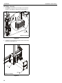
INSTALLATION INSTRUCTIONS
XCM7000
(shown installed to 1-1/2" NPT
columns as example only)
Extra Large Dual Column Ceiling Mount
Spanish Product Description
German Product Description
Portuguese Product Description
Italian Product Description
Dutch Product Description
French Product Description
XCM7000
XCM7000
Installation Instructions
DISCLAIMER
Milestone AV Technologies and its affiliated corporations and
subsidiaries (collectively "Milestone"), intend to make this
manual accurate and complete. However, Milestone makes no
claim that the information contained herein covers all details,
conditions or variations, nor does it provide for every possible
contingency in connection with the installation or use of this
product. The information contained in this document is subject
to change without notice or obligation of any kind. Milestone
makes no representation of warranty, expressed or implied,
regarding the information contained herein. Milestone assumes
no responsibility for accuracy, completeness or sufficiency of
the information contained in this document.
Chief® is a registered trademark of Milestone AV Technologies.
All rights reserved.
WARNING: Never operate this mounting system if it is
damaged. Return the mounting system to a service center for
examination and repair.
WARNING: Do not use this product outdoors.
NOTE: The XCM7000 dual column ceiling mounts are intended
to be used with the UL Listed CPA extension columns
and UL Listed CPA Ceiling Plates (not included):
CPA330, CPA365, CPA395.
The following UL Listed Chief ceiling plates WITHOUT
swaged collars (not included) may also be used:
CMA330, CMA345, CMA395.
--SAVE THESE INSTRUCTIONS-IMPORTANT SAFETY INSTRUCTIONS
WARNING: A WARNING alerts you to the possibility of
serious injury or death if you do not follow the instructions.
CAUTION: A CAUTION alerts you to the possibility of
damage or destruction of equipment if you do not follow the
corresponding instructions.
WARNING: Failure to read, thoroughly understand, and
follow all instructions can result in serious personal injury,
damage to equipment, or voiding of factory warranty! It is the
installer’s responsibility to make sure all components are
properly assembled and installed using the instructions
provided.
WARNING: Failure to provide adequate structural strength
for this component can result in serious personal injury or
damage to equipment! It is the installer’s responsibility to
make sure the structure to which this component is attached
can support five times the combined weight of all equipment.
Reinforce the structure as required before installing the
component.
WARNING: Exceeding the weight capacity can result in
serious personal injury or damage to equipment! It is the
installer’s responsibility to make sure the combined weight of
all components located within the mounting system of the
XCM7000 does not exceed a maximum weight capacity of
300 lbs (136.1 kg).
2
XCM7000
Installation Instructions
DIMENSIONS
TILT LOCKOUTS AT
-7.6°
-5°
0°
5°
10°
15°
20°
15.75
400.0
MAX VERTICAL
MOUNTING PATTERN
31.98
812.2
MAX HORIZONTAL
DIMENSIONS:
INCHES
[MILLIMETERS]
5° HOLE
-5° HOLE
DETAIL B
SCALE 1 : 2
DETAIL A
SCALE 1 : 2
DETAIL C
SCALE 1 : 2
DETAIL D
SCALE 1 : 2
0° HOLE
-7.6° HOLE
10° HOLE
10°
5°
B
15°
20°
E
C
D
A
7.6°
DETAIL E
SCALE 1 : 2
G
5°
DIMENSIONS:
3
INCHES
[MILLIMETERS]
XCM7000
Installation Instructions
LEGEND
4
Tighten Fastener
Pencil Mark
Apretar elemento de fijación
Marcar con lápiz
Befestigungsteil festziehen
Stiftmarkierung
Apertar fixador
Marcar com lápis
Serrare il fissaggio
Segno a matita
Bevestiging vastdraaien
Potloodmerkteken
Serrez les fixations
Marquage au crayon
Loosen Fastener
Drill Hole
Aflojar elemento de fijación
Perforar
Befestigungsteil lösen
Bohrloch
Desapertar fixador
Fazer furo
Allentare il fissaggio
Praticare un foro
Bevestiging losdraaien
Gat boren
Desserrez les fixations
Percez un trou
Phillips Screwdriver
Adjust
Destornillador Phillips
Ajustar
Kreuzschlitzschraubendreher
Einstellen
Chave de fendas Phillips
Ajustar
Cacciavite a stella
Regolare
Kruiskopschroevendraaier
Afstellen
Tournevis à pointe cruciforme
Ajuster
Open-Ended Wrench
Remove
Llave de boca
Quitar
Gabelschlüssel
Entfernen
Chave de bocas
Remover
Chiave a punte aperte
Rimuovere
Steeksleutel
Verwijderen
Clé à fourche
Retirez
By Hand
Optional
A mano
Opcional
Von Hand
Optional
Com a mão
Opcional
A mano
Opzionale
Met de hand
Optie
À la main
En option
Hex-Head Wrench
Security Wrench
Llave de cabeza hexagonal
Llave de seguridad
Sechskantschlüssel
Sicherheitsschlüssel
Chave de cabeça sextavada
Chave de segurança
Chiave esagonale
Chiave di sicurezza
Zeskantsleutel
Veiligheidssleutel
Clé à tête hexagonale
Clé de sécurité
Installation Instructions
XCM7000
TOOLS REQUIRED FOR INSTALLATION
3/32"
5/32"
3/16"
M5
1/2" or 13mm
#2
(included)
PARTS
[Interface Bracket Hardware Kit]
A (8)
M4x16mm
E (6)
M5x20mm
I (6)
M8x20mm
L (8)
.750x.323x.250
X (2)
[End cap]
C (6)
D (6)
M4x25mm M5x16mm
B (6)
M4x20mm
F (6)
M5x25mm
R (2)
10-24 x 1/4"
G (6)
M6x16mm
H (6)
M6x25mm
T (2)
3/16"
K (4)
M8x50mm
J (6)
M8x30mm
N (8)
M (8)
[Universal
.750x.344x.500
washer]
Z (4)
5/16"
Y (4)
1/4-20 x 1/2"
CC (4)
5/16"
S (2)
3/32"
Q (2)
[Bottom coupling]
(Used with 1-1/2"
NPT column system)
U (3)
5/32"
W (2)
1/4-20
P (1)
M5
[In bag
labeled "N"]
V (2)
1/4-20 x 2"
AA (8)
5/16"
BB (4)
5/16 x 3/4"
DD (4)
5/16 x 2"
EE (4)
[T-slot stud]
FF (2)
[Array head]
GG (2)
[Back cover]
KK (2)
[Interface bracket]
JJ (1)
[Mounting rail]
HH (2)
[Lower set
screw bracket]
5
XCM7000
Installation Instructions
INSTALLATION
9.
Repeat Steps 1 through 8 for remaining array head (FF).
NOTE: The following procedure assumes that 2 UL Listed CPA
or CMA ceiling plates (not included) and 2 extension
columns (not included) have been properly installed
following instructions provided with ceiling plates and
extension columns.
•
The ceiling plates and columns should be installed
approximately centered on mount with spacing
between columns to be NO LESS than 18". (See
Dimensions drawings.)
IMPORTANT ! : The weight of the system should be
evenly distributed across two ceiling plates.
NOTE: Proceed to Attaching Mount to 1-1/2" NPT Column
5
Adjustment bolt
8
8
7
Front of
array head
section or Attaching Mount to CPA Extension
Column section, as appropriate.
7
Attaching Mount to 1-1/2" NPT Column
1.
Turn the array head (FF) upside down. (See Figure 1)
2.
Remove AND SAVE two buttonhead screws from array
head. (See Figure 1)
3.
Remove and discard inner bracket from array head. (See
Figure 1)
2
6
(HH)
Figure 2
x2
Bottom of
array head
(FF)
5
10. Slide array head (FF) up from below onto installed column
(not included). (See Figure 3)
11. Thread bottom coupling (Q) onto installed column until tight,
with a minimum of four threads engaged. (See Figure 3)
12. Install and tighten one 10-24 x 1/4" set screw (R) into
bottom coupling (Q). (See Figure 3)
Inner
bracket
3
10
(FF)
Figure 1
CAUTION: WATCH FOR PINCH POINTS! Do not place
fingers between moveable parts.
4.
Turn array head upright. (See Figure 2)
5.
Turn adjustment bolt on top of array head to slide plate up
and enlarge opening on front of array head. (See Figure 2)
6.
Insert lower set screw bracket (HH) into array head (FF)
with three tabs towards sides and back. (See Figure 2)
7.
Fasten bracket (HH) into place in bottom of array head using
buttonhead screws (removed in Step 2) through sides of
array head and into side tabs of bracket (HH). (See Figure 2)
8.
12
(Q)
11
Slide plate (raised in Step 5) back into position by turning
adjustment bolt on top of array head. (See Figure 2)
Figure 3
6
(R)
Installation Instructions
XCM7000
13. Repeat Steps 10 through 12 for remaining array head (FF),
assuring that second array head is approximately level with
first installed array head.
2.
Partially fasten one 5/16" lock nut (AA) to each stud on
upper T-slot studs.
3.
Slide top T-slot studs (EE) with attached lock nuts (AA)
down into top openings on array heads (FF). (See Figure 6)
4.
Slide studs on lower T-slot studs (EE) into lower slots on
array head (FF) while bringing mounting rail against array
head.
5.
Tighten array head to mounting rail by tightening lock nuts
on upper T-slot studs and adding two 5/16" lock nuts (AA) to
lower T-slot studs. (See Figure 6)
Attaching Mount to CPA Extension Column
CAUTION: WATCH FOR PINCH POINTS! Do not place
fingers between moveable parts.
1.
Slide array head (FF) up from below onto installed column
(not included). (See Figure 4)
2.
Line up holes in sides of array head (FF) with holes in
column.
(FF)
(JJ)
(FF)
3
(Z) x 2
5
(AA) x 2
1
(CC) x 2
4
3
(DD) x 2
Figure 6
Figure 4
3.
4.
Install two 5/16" x 2" self-tapping screws (DD) through two
5/16" split washers (CC), two 5/16" flat washers (Z), sides
of array head (FF), and into installed column. (See Figure 4)
6.
Repeat for remaining array head (FF).
7.
Add one end cap (X) to each end of mounting rail, and
fasten in place using two 1/4-20 x 1/2" Phillips self-tapping
screws (Y) for each end cap. (See Figure 7)
Repeat Steps 1 through 3 for remaining array head (FF),
assuring that second array head is approximately level with
first installed array head.
(X)
Adding Mounting Rail
1.
Slide four T-slot studs (EE - two in top mounting rail slot and
two in bottom) into end of mounting rail (JJ). (See Figure 5)
(EE) x 4
1
7
(Y) x 2
(JJ)
Figure 7
Figure 5
7
XCM7000
8.
Installation Instructions
Tighten two 5/16" x 3/4" set screws (BB) against column.
(See Figure 8)
(L or M)
(BB) x 2
8
(N)
(FF)
2
Center of
bracket
Figure 8
(KK)
3
(A-K)
Attaching Interface Brackets to Displays
1.
Figure 10
Lower the latch mechanism on each interface bracket (KK).
(See Figure 9)
WARNING: IMPROPER INSTALLATION CAN LEAD TO
DISPLAY FALLING CAUSING SERIOUS PERSONAL
INJURY OR DAMAGE TO EQUIPMENT! Using screws of
improper size may damage your display. Properly sized
screws will easily and completely thread into display
mounting holes. If spacers are required, be sure to use longer
screws of the same diameter.
(KK)
3.
1
Select correct screws, spacers (if necessary) and universal
washers from the hardware bag (A-N) and attach brackets
(KK) to back of screen. (See Figure 10)
Attaching Displays to Mounting Rail
Latch
mechanism
WARNING: Exceeding the weight capacity can result in
serious personal injury or damage to equipment! It is the
installer’s responsibility to make sure the combined weight of
all components located within the mounting system of the
XCM7000 does not exceed a maximum weight capacity of
300 lbs (136.1 kg).
Figure 9
2.
Align the center of the interface bracket (KK) with center of
screen. (See Figure 10)
NOTE: The diamond-shape hole in the bracket corresponds to
CAUTION: BEFORE adding display to the mounting rail,
the center of the mount.
ensure end caps are in place at BOTH ends of mounting rail!
IMPORTANT ! : The interface bracket tilt may be adjusted
either before or after adding display to mounting rail. See
Adjustments section.
1.
8
Ensure that the latch mechanisms on interface brackets
(KK) are already lowered. (See Figure 9)
Installation Instructions
2.
3.
XCM7000
While supporting both sides of display, lower display onto
center of ceiling mount, hooking top of interface brackets
onto front of ceiling mount. (See Figure 11)
Raise the latch mechanism on both interface brackets to
lock bracket in place. (See Figure 11)
Tilt
NOTE: Two people will be required to adjust the tilt when the
display is installed.
The interface brackets allow -7.6° to 20° tilt, and can be locked
at -7.6°, -5°, 0°, 5°, 10°, 15° and 20° tilt.
1.
Adjust tilt as required. (See Figure 13)
2.
The tilt may be locked using one 1/4-20 x 2" button head
screw (V) and one 1/4-20 lock nut (W) per interface bracket.
(See Figure 13)
3.
Repeat for remaining interface bracket.
3
2
(W)
2
3
(V)
-5°
15°
3
Latch
mechanism
(Array heads/display not shown for clarity)
5°
20°
10°
-7.6°
Shown
locked at
0° tilt
Figure 11
Adjustments
CAUTION: Watch for pinch points! Do not place fingers
between moveable parts.
Height Adjustment and Leveling
The ceiling mounts allow up to 2 inches total adjustment.
1.
Turn the adjustment bolt in the direction necessary to level
or adjust height. (See Figure 12)
2.
Stop adjusting when the desired setting is reached.
(Display not shown)
Figure 13
Adjustment
1 bolts
Figure 12
9
XCM7000
Installation Instructions
OPTIONAL: Security
1.
OPTIONAL: Add padlock (not included) to each interface
bracket to lock display to ceiling mount. (See Figure 14)
Padlock
(Optional)
(Display not shown)
Figure 14
2.
Install back cover (GG) into four holes on back of both array
heads (FF). (See Figure 15)
(FF)
(GG)
(Display not shown)
Figure 15
10
Installation Instructions
XCM7000
11
XCM7000
Installation Instructions
USA/International
Europe
Chief, a products division of
Milestone AV Technologies
8800-002455 Rev00
2014 Milestone AV Technologies
www.chiefmfg.com
01/14
Asia Pacific
A
P
F
A
P
F
A
6436 City West Parkway, Eden Prairie, MN 55344
800.582.6480 / 952.225.6000
877.894.6918 / 952.894.6918
Franklinstraat 14, 6003 DK Weert, Netherlands
+31 (0) 495 580 852
+31 (0) 495 580 845
Office No. 1 on 12/F, Shatin Galleria
18-24 Shan Mei Street
Fotan, Shatin, Hong Kong
P 852 2145 4099
F 852 2145 4477