1
KVM Console to USB 2.0 Portable Laptop Crash Cart
Adapter with File Transfer & Video Capture
NOTECONS02
*actual product may vary from photos
DE: Bedienungsanleitung - de.startech.com
FR: Guide de l'utilisateur - fr.startech.com
ES: Guía del usuario - es.startech.com
IT: Guida per l'uso - it.startech.com
NL: Gebruiksaanwijzing - nl.startech.com
PT: Guia do usuário - pt.startech.com
For the most up-to-date information, please visit: www.startech.com
Manual Revision: 10/07/2014
FCC Compliance Statement
This equipment has been tested and found to comply with the limits for a Class B digital
device, pursuant to part 15 of the FCC Rules. These limits are designed to provide reasonable
protection against harmful interference in a residential installation. This equipment generates,
uses and can radiate radio frequency energy and, if not installed and used in accordance with
the instructions, may cause harmful interference to radio communications. However, there
is no guarantee that interference will not occur in a particular installation. If this equipment
does cause harmful interference to radio or television reception, which can be determined by
turning the equipment off and on, the user is encouraged to try to correct the interference by
one or more of the following measures:
• Reorient or relocate the receiving antenna.
• Increase the separation between the equipment and receiver.
• Connect the equipment into an outlet on a circuit different from that to which the receiver
is connected.
• Consult the dealer or an experienced radio/TV technician for help.
Use of Trademarks, Registered Trademarks, and other Protected Names and Symbols
This manual may make reference to trademarks, registered trademarks, and other
protected names and/or symbols of third-party companies not related in any way to
StarTech.com. Where they occur these references are for illustrative purposes only and do not
represent an endorsement of a product or service by StarTech.com, or an endorsement of the
product(s) to which this manual applies by the third-party company in question. Regardless
of any direct acknowledgement elsewhere in the body of this document, StarTech.com hereby
acknowledges that all trademarks, registered trademarks, service marks, and other protected
names and/or symbols contained in this manual and related documents are the property of
their respective holders.
Instruction Manual
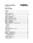
Table of Contents
Introduction.............................................................................................1
Packaging Contents.................................................................................................................................. 1
System Requirements............................................................................................................................... 1
Installation...............................................................................................2
Hardware Installation............................................................................................................................... 3
LED Indicators............................................................................................................................................. 3
Operation.................................................................................................4
Toolbar........................................................................................................................................................... 4
Zoom Menu.................................................................................................................................................. 6
Video Menu.................................................................................................................................................. 7
File Transfer Menu...................................................................................................................................... 13
Keyboard Menu.......................................................................................................................................... 15
Mouse Menu................................................................................................................................................ 16
Toolbar Menu.............................................................................................................................................. 18
Toubleshooting.......................................................................................19
Specifications...........................................................................................20
Technical Support...................................................................................21
Warranty Information.............................................................................21
Instruction Manual
i
Introduction
You must install the provided software on the laptop to be able to use the USB Crash
Cart Adapter. No changes are needed on the server(s) being controlled. The USB Crash
Cart Adapter can be connected or disconnected any time you wish. The software does
not need to be started first, nor do you need to shut it down before unplugging the
USB Crash Cart Adapter.
Packaging Contents
• 1 x USB Crash Cart Adapter
• 1 x USB A to Mini-B cable
• 1 x Driver and Software USB flash drive
System Requirements
Notebook Requirements
• USB 2.0 enabled notebook computer
• 20MB available hard drive space
• 24-bit capable display
• Windows® 8 / 8.1 (32/64bit), 7 (32/64), Vista(32/64), XP(32/64), Windows® Server
2008 R2, 2003(32/64), Mac OS 10.6 and later (Tested up to 10.10), and Linux 2.6.x 3.13.x (32/64bit)
Server Requirements
• VGA enabled video card (DVI supported via optional DVIVGAMF adapter)
• USB keyboard and mouse support
Instruction Manual
1
Installation
Windows
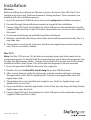
Before installing the software on Windows, please disconnect the USB Crash Cart
Adapter and cancel any “Add new hardware” dialog windows. These windows can
interfere with the installation process.
1. Insert the provided USB flash drive and run the setup.exe installation program.
2. Proceed through the installation prompts to complete the installation.
3. Connect the USB Crash Cart Adapter to a free USB port on the notebook using the
supplied USB mini-B to A cable. The other connections to a server are not needed at
this point.
4. A message should pop-up entitled Found New Hardware.
5. Windows should find the device driver files and install them automatically. This is a
one-time step.
6. The product is ready to be used now, and the main application may be launched
now. There is no need to reboot.
Mac OS X
Note: For Mac OSX version 10.8 or later an exception may need to be made to run
unsigned programs. To do this hold the Command key and click on the program’s icon
to open the Applications folder. Control-click or Right-click on this icon in the Finder
window and then select Open. This will enable the program to launch normally.
1. Insert the provided USB flash drive into the computer.
2. Double-click on the MacOSX-install.dmg file on the USB flash drive.
3. After a short delay to verify the disk image, a finder window will open showing
the application and a link to /Applications. Drag the main application onto the
Applications link.
4. The application is now installed and ready for use: Find it in /Applications and
double click on it to start.
5. If you would like to add this application to the Dock, you can drag and drop it from /
Applications onto the Dock.
6. Connect the USB Crash Cart Adapter to a free USB port on the notebook using the
supplied USB mini-B to A cable.
Instruction Manual
2
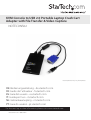
Hardware Installation
Once the drivers and software for the USB Crash Cart Adapter are installed on the
notebook computer, it can be plugged into the server.
Connect the attached VGA cable and the USB type A cable into the desired server. For
DVI-I (analog) computer systems, please use a DVI to VGA adapter (StarTech.com ID:
DVIVGAMF).
Supports File Transfer
Supports Video Capture
USB Keyboard/mouse
VGA Video
USB 2.0
*
*
=
/
9
retnE
6
0
8
5
3
leD
ec a p s k c
7
2
aB
=
}
r etn E
4
1
0
lrtC
{
0
P
“‘
9
O
;:
t fihS
;:
tlA
8
L
>
tlA
I
7
U
K
<
6
Y
J
M
5
T
H
4
G
N
B
3
R
F
V
E
2
W
D
C
1
Q
S
X
;:
A
Z
b aT
C
k c oL s p a
tlA
;:
t fihS
OR
OR
lrtC
;:
Laptop/Netbook
Laptop KVM Console Adapter
(NOTESONS02)
PC
Kiosk/ATM
Server Rack
LED Indicators
Server KB/Mouse: This lights up when the emulated USB keyboard/mouse is working.
It will blink briefly whenever the emulated mouse moves, or emulated key is pressed.
Constant flashing indicates some problem with the USB connection to the server. This
can happen if disconnected, or if the host’s operating system is not enumerating the
USB device.
Server VGA: This indicates a valid VGA video signal is being received. It will be
off if nothing is connected (and in some power saving modes) and may flash if an
unsupported video mode or other trouble is seen with the video signal. This light will
not turn on, regardless of the video input status, until the adapter is connected to the
application software at least once.
User Console Link/Activity: This lights up when a good connection to the laptop is
established. If flashing, it indicates the USB to the laptop is not connected or being
ignored. Blinks briefly when video data is sent to the laptop.
If all the lights are off, then this means the USB Crash Cart Adapter has no power from
either USB connection. Under normal operation, either USB port can provide enough
power to operate the unit. The USB keyboard/mouse emulation is always active, even if
the laptop USB is disconnected.
Instruction Manual
3
Operation
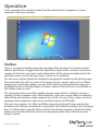
Once connected, the real-time video from the attached host computer is shown
centered in the main window.
Toolbar
There is an optional toolbar along the top edge of the window. This toolbar may be
hidden, detached or dragged onto the other three edges of the window. It provides a
number of shortcuts and some status information. All functions are duplicated in the
pull down menus across the top of your screen, so it is optional.
You can move and/or detach the toolbar by dragging the handle on the left/top edge.
Once detached, the red X or circle in the upper corners can be used to close it. When
dragging or moving the toolbar, you can stick it (dock) to the top/bottom edge, if in
horizontal mode, or left/right edges if vertical. Some of these features are available in
the Toolbar menu as well.
The right most status area of the toolbar reports some statistics while the system is
running. The first number is the USB bandwidth, in bits per second. When no motion is
detected by our hardware video compression, no bits are sent. Noisy video cards and
ongoing video animations, will cause a constant stream of USB traffic.
The next two numbers (ex. 30Hz and 44fps) report the achieved frame rates for the
hardware and software components respectively. The hardware number (Hz) will range
from 1 to 85Hz, but is typically 30Hz or 60Hz. The software number is limited to 60 fps
(frames per second) maximum and varies depending what other software on your
laptop is doing.
Instruction Manual
4
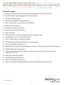
From left to right:
1. Change orientation of tool bar between horizontal (shown) and vertical.
2. Quit the Pocket Console application immediately.
3. Fine-tune video picture.
4. Open Video-related settings window.
5. Take a screenshot, save as PNG, JPG, BMP file.
6. Record (Video Capture)
7. Loop Record (Video Capture)
8. Play previously recorded video
9. Pause playback
10. Make a Movie (.avi file) out of previously recorded video
11. Toggle full-screen vs. windowed mode.
12. Go to 100% zoom, or largest possible.
13. (50%) Shows current zoom factor as a percentage.
14. Disk control (file transfer) icon
15. Keyboard status (red X shown if there is an issue). Click to open special keys window.
16. (USB) USB mode for keyboard.
17. Caps lock indicator/button (green if active, shown inactive). Click to simulate pressing caps lock.
18. Num lock indicator/button.
19. Scroll lock indicator/button.
20. Send Ctrl-Alt-Del to the server.
21. Status area. Shows USB bandwidth, hardware and software frame rates.
Instruction Manual
5
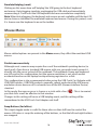
Zoom Menu
In the Zoom menu there are a number of options to set the zoom factor and resize the
window to achieve that zoom factor. For example, if the attached server is running at
XGA resolution (1024 x 768), and you select 50% zoom, the main window will be set to
a size of approximately 512 x 384.
Note: Please keep in mind that not all zoom factors will be possible, as some notebook
screens are too small for the larger percentages. If so, the software will resize to the
largest window possible.
Since many notebooks have smaller screens, you may wish to run this program
maximized. Full-screen mode is supported, where the window decorations are
removed and other applications are hidden. Click on the full-screen/window icon (
on the toolbar or select it from the Zoom menu.
To get out of full screen mode, click the icon again. If the toolbar is disabled when you
enter full-screen mode, a smaller toolbar is provided with only the Fullscreen and Quit
options. This toolbar floats and may be moved out of your way, but cannot be hidden
completely.
Also in the Zoom menu is an option to center the window on the screen. This can
be handy when it is off the edge of the screen. There is also a shortcut for maximize
(toggle). This is the same as clicking the maximize button in the title bar of the main
window.
Other Notes
• If the laptop is widescreen (16:10 aspect, or 1280x800, etc), it may be helpful to
locate the toolbar along the left or right vertical edge. This provides more usable
screen height, and if the server’s screen is square (4:3 aspect) the left and right
vertical edges would not be used.
• This program will not enlarge video, only shrink it. Therefore, text mode
(720x480 or similar) will not be enlarged to fill your screen.
• The toolbar is automatically disabled when you select a Zoom factor below 50%.
You need to enable it manually when you return to a larger size.
• Unusable parts of the window are shown in grey. This happens because the video is
scaled by an integer factor of 1/16 and due to other rounding issues.
Instruction Manual
6
)
Video Menu
There are a number of options available under the Video menu, including: Auto finetune picture, Video Settings, Video capture and Save PNG snapshot.
Auto fine-tune picture
Use to automatically adjust the sampling phase of the video. This makes the picture
sharper and reduces USB traffic. This is generally not required since this operation is
automatically performed when video is applied. The picture will freeze for about one
second while the calibration is performed.
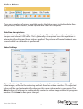
Video Settings
Picture Positioning - These four arrows may be used to fine-tune the position of the
video image, similar to the centering controls found on video monitors. The adjusted
values will be used automatically whenever this same video mode is seen again. The
Auto button will attempt to automatically center the video image within the program
window. Click Save to keep your changes.
Instruction Manual
7
Sampling Phase (Sharpness) - This slider allows you to override the automatic phase
adjustment. Press Auto to perform auto phase again. The numbers shown under the
slider are the phase (angle) of the control. Click Save to keep your changes.
Noise Filters - The hardware implements two filters to reduce USB traffic and improve
picture quality. By default they are both enabled and set to one. You may override and
save customized settings (which will apply to all video modes).
The first ‘Noise’ filter helps to remove speckle noise. There is usually no visual effect to
this filter, except that at high values, moving the mouse may leave some pixels behind.
The second ‘Flatness’ filter converts regions that are nearly all the same color into
exactly the same color to aid with compression. At higher values, color banding will be
much more visible. Click Save to keep your changes.
Color Brightness – Adjust the sliders to fix dark or over-saturated color. The Auto button
will attempt to automatically adjust the color for you. The Default button will return
the sliders to their factory-set positions.
Color Offset Adjustments – Adjust the sliders to fix black levels in the image. The Auto
button will attempt to automatically adjust the levels for you. The Default button will
return the sliders to their factory-set positions.
Save PNG snapshot
Use this function to take a screenshot of the current window contents and save it into
a PNG, JPG or BMP file. The snapshot happens as soon as the menu item (or toolbar
button) is clicked. You are then given a chance to choose where the image file should
be stored. A default filename is provided based on the current time.
Snapshots are always stored at full resolution and contain the whole screen.
Capture Video Mode Details
Displays and then saves the current video mode settings used on the server to a text
file.
DDC
Sets the default maximum video resolution on the USB Crash Cart Adapter.
Instruction Manual
8
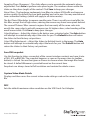
Video Capture
Record
The record function captures the current display until stopped by the user, or until the
user-defined period is reached (functions only when the NOTECONS02 is connected).
Clicking the Record button or selecting Video > Record from the drop-down menu will
bring up a dialog box where you can choose a destination folder where the recorded
files will be stored.
Note: Ensure you have “read and write” access to your chosen destination folder,
otherwise an error message will be displayed and recording will stop.
Recording can be stopped by either clicking the Record button again, or selecting
Video > Record from the drop-down menu. Otherwise, the capture will continue until
the user-defined time period is reached. After choosing your destination folder, set the
maximum record time (1-3600 seconds; 3600 seconds = 1 Hour). Values outside the
1-3600 range will be automatically reset to 1 or 3600.
Note: The Playback / Pause, Make a Movie and File Transfer functions are disable
during video capture.
Loop Record
The Loop Record function continually captures the latest video in the user-defined
duration until stopped (functions only when the NOTECONS02 is connected). This
function is useful when you’re not sure when you will capture the video you need, but
don’t want to capture hours of footage.
Clicking the Loop Record button or selecting Video > Loop Record from the drop-down
menu will bring up a dialog box where you can choose a destination folder where the
recorded files will be stored.
Instruction Manual
9
Note: Ensure you have “read and write” access to your chosen destination folder,
otherwise an error message will be displayed and recording will stop.
Recording can be stopped by either clicking the Loop Record button again, or
selecting Video > Loop Record from the drop-down menu.
After choosing your destination folder, set the maximum record time for each video
(1-3600 seconds; 3600 seconds = 1 Hour). Values outside the 1-3600 range will be
automatically reset to 1 or 3600. If the pre-set time is Y seconds, the final record time
could be in the range of Y - 2Y seconds.
Note: The Playback / Pause, Make a Movie and File Transfer functions are disabled
during video capture.
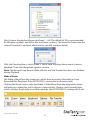
Playback/Pause
The Playback / Pause functions enable viewing of Recorded or Loop Recorded files
(functions if the NOTECONS02 is connected or disconnected).
Clicking the Playback button or selecting Video->Playback from the drop-down menu
will bring up a dialog box for you to choose which recorded folder you would like to
play. Choose a valid record folder, which contains the private record files made by the
NOTECONS02, starting with 0.out.
Instruction Manual
10
Next, choose the playback frame rate from 1 – 60 (The default of 30 is recommended
for Windows systems, and 60 for Mac and Linux systems). The lower the frame rate, the
slower the record is replayed, which means you will see more details.
Click the Pause button or select Video > Pause from the drop-down menu to pause
playback. Then click the button again to resume.
Note: The Record, Loop Record, Make a Movie and File Transfer functions are disabled
during Playback.
Make a Movie
The Make a Movie function creates an .avi file from a previous Recorded or Loop
Recorded files (functions if the NOTECONS is connected or disconnected).
Clicking the Movie icon or selecting Video > MakeMovie from the drop-down menu
will bring up a dialog for you to choose a source folder. Choose a valid record folder,
which contains the private record files made by the NOTECONS02, starting with 0.out.
Instruction Manual
11
From the next window, choose the output resolution of the avi file.
Note: If the recording was created using a resolution larger than the chosen output
resolution, the output movie may look squished.
Note: The Record, Loop Record, Playback and File Transfer functions are disabled when
using the Make a Movie function.
Instruction Manual
12
File Transfer Menu
File transfer works like a removable USB drive. Instead of a real drive, it creates a Disk
Image on the host computer that holds the files. Only one computer at a time may
access the image. When created (like plugging in the USB drive) the target computer
can read and write to the disk image but the host cannot. The virtual USB drive can be
used by any program or operating system without special drivers.
• Disk images are dynamic. E.g. If you create a 10GB disk and copy a 1MB file it will use
only 1MB plus overhead. Large images are less efficient and may take up more space
when copying many small files.
• Disk Images use the VHD format are compatible with Microsoft Windows and can be
mounted by Windows Explorer.
• ISO CD-ROM and DVD images can also be used for read only storage. You can install
an operating system without burning a real CD.
• You can also drag-and-drop files onto the video window to automatically copy files
and create a temporary image (if none are selected).
• Press the disk icon (
Instruction Manual
) on the toolbar to open the Disk Control window.
13
Browse - Open an existing image file (supports dynamic VHD files and ISO images).
New - Create a new disk image (you will be prompted to specify your desired size).
Insert - Connect disk image to target computer. If no disk image is loaded it will create
a temporary one. Temporary images will be deleted when the program closes.
Eject - Remove the disk image from the target computer.
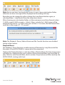
View Files – Opens the Disk Image Viewer window to show the directory tree view and
file list for the currently selected directory (pictured below). You can drag-and-drop
files onto the file list to copy.
• Right-clicking a directory from the left pane will give you the option of Extracting
the entire directory to a location on your connected host computer
• Right-clicking in the right pane gives you Extract, Delete and Add file operations, as
well as the ability to create a New Directory
Add Files - Open up a file dialog to quickly add files. If no disk image is loaded it will
create a temporary one.
Extract All - Open a file dialog to extract the entire contents of the image to the host PC.
Read and Write speed - Shows current data transfer rate. Will be slower for many small
files and faster for large files.
Disk Size - Size of currently inserted disk image.
Prevent Remove - Shows a “1” to indicate that removal may damage file contents. Be
sure to eject from operating system first.
Instruction Manual
14
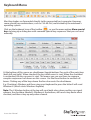
Keyboard Menu
Most keystrokes are forwarded directly to the connected host computer. However,
some special key combinations, such as Ctrl-Alt-Del, are blocked by the notebook’s
operating system.
Click on the keyboard icon of the toolbar (
), or use the menu option More special
keys to bring up a dialog box with common special key sequences that you can send
manually.
At the bottom of this menu are checkboxes (toggle buttons) for each of the meta keys
(both left and right). When checked, the key-down event is sent. When the checkbox
is unchecked, the key-up event is sent. This means you can use them to compose
complex sequences not shown on this screen. Use the Reset button to uncheck all
boxes. Clicking any of the keys above the line also resets the checkboxes.
E.g. Checking L-Window and then using your keyboard to press the letter E will send
Window+E (which starts Windows Explorer)
Note: The L-Window button at the top will send both a key-down and key-up signal,
whereas the checkbox labeled L-Window at the bottom, will send a key-down when
checked, and then a key-up only when cleared.
Instruction Manual
15
Simulate Hotplug (reset)
Clicking on this menu item will ‘hotplug’ the USB going to the host keyboard
and mouse. Hot plugging simulates unplugging the USB cable and immediately
reconnecting it. It will reset the USB keyboard and mouse emulation completely.
Note: When hot-plugging, the keyboard and mouse are not available until the host OS
device driver re-initializes the emulated keyboard and mouse. During this period, a red
X is shown over the keyboard icon on the toolbar.
Mouse Menu
Mouse related options are present in the Mouse menu; they affect the emulated USB
mouse.
Disable mouse entirely
Although most scenarios may require the use of the notebook’s pointing device (ie.
touch pad), if you have a standard USB mouse with you, you might want connect it
directly into the server instead of the notebook. The notebook screen and keyboard
are still used in this configuration, but the mouse emulation is not, which avoids
accidental touches on the laptop touchpad being registered as a click.
This configuration is also recommended when using the USB Crash Cart Adapter with
USB KVM switches. USB KVM products generally cannot understand the USB mouse
emulation device because of its advanced use of the HID (Human Interface Device)
standard.
In this mode, the mouse cursor is shown as a circle with a line (
you that clicks won’t be effective in that window.
). This is to remind
Changes to this setting will cause a USB hotplug event, and this setting will be
remembered in the USB Crash Cart Adapter unit itself.
Swap Buttons (for lefties)
This simple toggle mode is useful for those who use their left hand to control the
mouse. All it does is swap the ordering of the buttons, so that the left and right buttons
are swapped.
Instruction Manual
16
This setting is remembered on the laptop. Please keep in mind that the operating
system may also be swapping buttons to suit your preferences. It’s not always clear
how many swaps are needed, and which layer is doing the swapping. Experimentation
is suggested.
To release captured mouse...
In absolute mouse mode, you may simply move the laptop mouse over the window
and click as desired. In relative mode, the mouse doesn’t do anything until you click
once on the desktop. This captures the mouse and subsequent clicks and motion are
sent to the controlled host. A dialog is shown to remind you how to get back to your
laptop desktop.
To release the captured mouse, we offer two methods: make a circle gesture with
mouse or press “Alt+Ctrl+Shift” at the same time. The circle gesture is disabled by
default.
The gesture method is helpful for systems that may not have a keyboard. Simply move
the mouse in circle (with no mouse buttons pressed). It can be clockwise or counterclockwise. If it doesn’t work at first, just keep circling.
One or both of these methods must be selected at all times.
MacOS X Scaling
This mode is enabled by default, and applies a special adaptive scaling factor to
maintain perfect alignment when using the crash cart adapter with Mac OS X
computers.
Motion reporting mode
The current mouse motion reporting mode is indicated on this submenu. You also
have the option of forcing the system into relative mode.
We expect any BIOS system that uses the USB mouse will probably not support
absolute mode. Similarly, programs that run in DOS with the BIOS converting USB
events into legacy PS/2 mouse events will not be able to understand absolute mouse
events.
The USB Laptop Console will drop down to relative mode when the host operating
system indicates that it does not support absolute mode (there is a way to do this over
USB protocol). But you may force relative mode as well. This causes a USB hotplug
event and is remembered internal to the USB Laptop Console itself. This might be
needed if the computer doesn’t correctly implement the USB HID specification.
Instruction Manual
17
Relative vs. absolute motion
Conventional mice are very simple devices. When they are moved across a desk, they
simply report to the computer how far they have been moved. If you move the mouse
left an inch, a relative number (say X=-400, Y=0) is reported to the computer. The host
O/S takes this number and applies some user preferences to it and moves the onscreen mouse pointer to the left. Of course if the mouse is already in the top left corner,
then the on-screen mouse pointer doesn’t move.
When emulating a mouse, it is best if the controlled computer acts like a window
on your laptop screen. For that to happen, you want to direct the on-screen mouse
pointer to a specific screen location so we want to send absolute screen coordinates,
not relative motion events to the controlled host.
The USB H.I.D (Human Interface Devices) standard allows us to define a special USB
mouse that operates somewhat like a touch screen and simply tells the host where it
wants the mouse pointer to be. This works perfectly for modern Windows and Mac OS
X systems.
But there are USB KVM systems, USB to PS/2 convertors, DOS programs, simpler
operating systems and other situations where a simple USB relative mouse is needed.
For this reason, we support operation in relative mode.
In Relative mode, this program will `capture’ your mouse into its control window. This
must be done to convert your laptop mouse events back into relative events and send
those to the controlled system. While the mouse is captured, you cannot do anything
else with your system except control the attached computer.
Toolbar Menu
This menu provides a more direct way to control the toolbar. You can easily ‘dock’ or
‘float’ the toolbar, as well as hide or show it. The current status of the toolbar is shown
as check marks beside these choices.
The state of the toolbar (floating, docked, vertical, horizontal, position, etc.) is
remembered when the program is closed and then reopened. However, if you wish to
return to the default layout, use the Restore default window layout option.
Instruction Manual
18
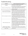
Toubleshooting
Symptom
No lights
Problem/Suggested Course of Action
Adapter has no power from either USB
connection. Try other USB ports.
Black bar on left/top of image
Use the Picture Positioning arrows on the Video
Settings dialog to shift the image leftwards /
upwards until no black can be seen. Be sure to
save your change.
User Console LED flashing or
software says not connected
Verify the device drivers are correctly installed
(Windows only): Unplug the adapter. Reboot.
Plug in the adapter. No dialog from Windows
about `found new hardware’ should be seen.
Red X over keyboard in toolbar
The emulated USB keyboard and/or mouse is
not being handled by the attached computer.
It might be disconnected, powered down, or
the O/S may be halted. When in this state, the
keyboard and mouse will not do anything. Try
using the (Simulate Hotplug (reset) command in
the Keyboard menu,
KVM switch doesn’t work
When using a USB KVM switch, rather than a
direct connection to a server, we recommend
disabling the USB mouse emulation or forcing
relative mouse motion mode. Disabling the
USB mouse emulation simplies the USB prole
we present to the KVM switch, and even the
most basic USB implementation should be able
to understand and support our keyboard and
mouse in relative mode.
Toolbar is gone / Always
fullscreen / Window stuck too
big or small
Use the menu item: Toolbar > Restore default
window layout to restore window positions and
toolbar state.
Instruction Manual
19
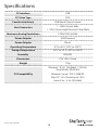
Specifications
PC Interface
USB
PC Video Type
VGA
Console Interface(s)
USB Mini-B (5 pin) Female
Host Connectors
1 - USB A (4 pin) Male
1 - VGA (15 pin; High Density D-Sub) Male
Maximum Analog Resolutions
1920x1200 @ 60Hz
Power Adapter
USB-Powered
Power Adapter
Plastic
Operating Temperature
0°C to 40°C (32°F to 104°F)
Storage Temperature
-40°C to 70°C (-40°F to 158°F)
Humidity
80% RH
Dimensions
73 x 135 x 15mm
Weight
170g
Windows® 8 / 8.1 (32/64bit), 7 (32/64),
Vista(32/64), XP(32/64)
Windows Server® 2012, 2008 R2
OS Compatibility
Mac OS® 10.x (Tested up to 10.9)
Linux 2.6.x - 3.5.x (32/64bit)
Instruction Manual
20
Technical Support
StarTech.com’s lifetime technical support is an integral part of our commitment to
provide industry-leading solutions. If you ever need help with your product, visit
www.startech.com/support and access our comprehensive selection of online tools,
documentation, and downloads.
For the latest drivers/software, please visit www.startech.com/downloads
Warranty Information
This product is backed by a two year warranty.
In addition, StarTech.com warrants its products against defects in materials
and workmanship for the periods noted, following the initial date of purchase.
During this period, the products may be returned for repair, or replacement with
equivalent products at our discretion. The warranty covers parts and labor costs only.
StarTech.com does not warrant its products from defects or damages arising from
misuse, abuse, alteration, or normal wear and tear.
Limitation of Liability
In no event shall the liability of StarTech.com Ltd. and StarTech.com USA LLP (or their
officers, directors, employees or agents) for any damages (whether direct or indirect,
special, punitive, incidental, consequential, or otherwise), loss of profits, loss of business,
or any pecuniary loss, arising out of or related to the use of the product exceed the
actual price paid for the product. Some states do not allow the exclusion or limitation
of incidental or consequential damages. If such laws apply, the limitations or exclusions
contained in this statement may not apply to you.
Instruction Manual
21
Hard-to-find made easy. At StarTech.com, that isn’t a slogan. It’s a promise.
StarTech.com is your one-stop source for every connectivity part you need. From
the latest technology to legacy products — and all the parts that bridge the old and
new — we can help you find the parts that connect your solutions.
We make it easy to locate the parts, and we quickly deliver them wherever they need
to go. Just talk to one of our tech advisors or visit our website. You’ll be connected to
the products you need in no time.
Visit www.startech.com for complete information on all StarTech.com products and
to access exclusive resources and time-saving tools.
StarTech.com is an ISO 9001 Registered manufacturer of connectivity and technology
parts. StarTech.com was founded in 1985 and has operations in the United States,
Canada, the United Kingdom and Taiwan servicing a worldwide market.