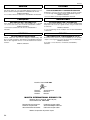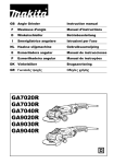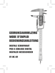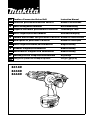
1
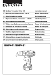
GB Cordless Percussion-Driver Drill
Instruction Manual
F
Perceuse percussion-visseuse sans fil
Manuel d’instructions
D
Akku-Schlagbohrschrauber
Betriebsanleitung
I
Trapano avvitatore percussione a batteria
Istruzioni per l’uso
NL Accu slagboor/schroevedraaier
Gebruiksaanwijzing
E
Taladro atornillador con percusión a batería Manual de instrucciones
P
Berbequim de percussão a bateria
DK Akku-slagboremaskine/skruemaskine
Manual de instruções
Brugsanvisning
S
Sladdlös slagborr/skruvmaskin
Bruksanvisning
N
Batteridrevet slagbor med skrutrekker
Bruksanvisning
SF Akkukäyttöinen iskupora/ruuvinväännin
Käyttöohje
GR Ασύρµατο κρουστικ κατσαβίδι-τρυπάνι
Οδηγίες χρήσεως
8414D
8434D
8444D
1
3
2
1
2
B
A
4
5
3
4
8
6
5
7
9
6
10
14
15
11
13
12
7
2
8
16
18
19
17
9
10
20
11
12
22
23
21
13
14
3
ENGLISH
Explanation of general view
1
2
3
4
5
6
7
8
Button
Battery cartridge
Switch trigger
Reversing switch lever
Speed change lever
Action mode change lever
Arrow
Adjusting ring
9
10
11
12
13
14
15
16
Graduations
Steel band
Grip base
Side grip
Protrusion
Groove
Sleeve
Bit
17
18
19
20
21
22
23
Bit holder
Depth rod
Clamp screw
Blow-out bulb
Limit mark
Brush holder cap
Screwdriver
SPECIFICATIONS
Model
8414D
Capacities
Concrete............................................... 13 mm
Steel ..................................................... 13 mm
Wood .................................................... 45 mm
Wood screw.......................................... 6 mm x 75 mm
Machine screw ..................................... 6 mm
No load speed (min-1)
High (3)................................................. 0 – 1,600
Medium (2) ........................................... 0 – 550
Low (1) ................................................. 0 – 300
Blows per minute (min-1)
High (3)................................................. 0 – 24,000
Medium (2) ........................................... 0 – 8,250
Low (1) ................................................. 0 – 4,500
Overall length .......................................... 259 mm
Net weight ............................................... 2.4 kg
Rated voltage .......................................... D. C. 12 V
• Due to our continuing program of research and development, the specifications herein are subject to change
without notice.
• Note: Specifications may differ from country to country.
5.
6.
7.
Intended use
The tool is intended for impact drilling in brick, concrete
and stone as well as for drilling without impact in wood,
metal, ceramic and plastic.
8.
9.
Safety hints
For your own safety, please refer to the enclosed safety
instructions.
8434D
8444D
14 mm
13 mm
50 mm
6 mm x 75 mm
6 mm
16 mm
13 mm
65 mm
10 mm x 89 mm
6 mm
0 – 1,700
0 – 600
0 – 300
0 – 1,700
0 – 600
0 – 300
0 – 25,500
0 – 9,000
0 – 4,500
259 mm
2.5 kg
D. C. 14.4 V
0 – 25,500
0 – 9,000
0 – 4,500
259 mm
2.7 kg
D. C. 18 V
Hold the tool firmly with both hands.
Keep hands away from rotating parts.
Do not leave the tool running. Operate the tool
only when hand-held.
Do not touch the bit or the workpiece immediately after operation; they may be extremely hot
and could burn your skin.
Some material contains chemicals which may be
toxic. Take caution to prevent dust inhalation
and skin contact. Follow material supplier safety
data.
SAVE THESE INSTRUCTIONS.
ADDITIONAL SAFETY RULES FOR POWER
TOOL
GEB003-1
DO NOT let comfort or familiarity with product
(gained from repeated use) replace strict adherence
to hammer drill safety rules. If you use this power
tool unsafely or incorrectly, you can suffer serious
personal injury.
1. Wear ear protectors with impact drills. Exposure
to noise can cause hearing loss.
2. Use auxiliary handles supplied with the tool.
Loss of control can cause personal injury.
3. Hold tools by insulated gripping surfaces when
performing an operation where the cutting tool
may contact hidden wiring or its own cord. Contact with a “live” wire will make exposed metal
parts of the tool “live” and shock the operator.
4. Always be sure you have a firm footing.
Be sure no one is below when using the tool in
high locations.
4
IMPORTANT SAFETY INSTRUCTIONS FOR
CHARGER & BATTERY CARTRIDGE
ENC004-1
1.
2.
3.
4.
5.
6.
Before using battery cartridge, read all instructions and cautionary markings on (1) battery
charger, (2) battery, and (3) product using battery.
Do not disassemble battery cartridge.
If operating time has become excessively
shorter, stop operating immediately. It may
result in a risk of overheating, possible burns
and even an explosion.
If electrolyte gets into your eyes, rinse them out
with clear water and seek medical attention right
away. It may result in loss of your eyesight.
Always cover the battery terminals with the battery cover when the battery cartridge is not
used.
Do not short the battery cartridge:
7.
8.
9.
(1) Do not touch the terminals with any conductive material.
(2) Avoid storing battery cartridge in a container
with other metal objects such as nails, coins,
etc.
(3) Do not expose battery cartridge to water or
rain.
A battery short can cause a large current flow,
overheating, possible burns and even a breakdown.
Do not store the tool and battery cartridge in
locations where the temperature may reach or
exceed 50°C (122°F).
Do not incinerate the battery cartridge even if it
is severely damaged or is completely worn out.
The battery cartridge can explode in a fire.
Be careful not to drop or strike battery.
SAVE THESE INSTRUCTIONS.
Tips for maintaining maximum battery life
1.
2.
3.
4.
Charge the battery cartridge before completely
discharged.
Always stop tool operation and charge the battery cartridge when you notice less tool power.
Never recharge a fully charged battery cartridge.
Overcharging shortens the battery service life.
Charge the battery cartridge with room temperature at 10°C – 40°C (50°F – 104°F). Let a hot battery cartridge cool down before charging it.
Charge the Nickel Metal Hydride battery cartridge when you do not use it for more than six
months.
FUNCTIONAL DESCRIPTION
CAUTION:
• Always be sure that the tool is switched off and the battery cartridge is removed before adjusting or checking
function on the tool.
Installing or removing battery cartridge (Fig. 1)
• Always switch off the tool before insertion or removal of
the battery cartridge.
• To remove the battery cartridge, withdraw it from the
tool while pressing the buttons on both sides of the cartridge.
• To insert the battery cartridge, align the tongue on the
battery cartridge with the groove in the housing and slip
it into place. Always insert it all the way until it locks in
place with a little click. If not, it may accidentally fall out
of the tool, causing injury to you or someone around
you.
• Do not use force when inserting the battery cartridge. If
the cartridge does not slide in easily, it is not being
inserted correctly.
Switch action (Fig. 2)
CAUTION:
• Before inserting the battery cartridge into the tool,
always check to see that the switch trigger actuates
properly and returns to the “OFF” position when
released.
To start the tool, simply pull the switch trigger. Tool speed
is increased by increasing pressure on the switch trigger.
Release the switch trigger to stop.
Reversing switch action (Fig. 3)
This tool has a reversing switch to change the direction of
rotation. Depress the reversing switch lever from the “A”
side for clockwise rotation or from the “B” side for counterclockwise rotation.
When the reversing switch lever is in the neutral position,
the switch trigger cannot be pulled.
CAUTION:
• Always check the direction of rotation before operation.
• Use the reversing switch only after the tool comes to a
complete stop. Changing the direction of rotation
before the tool stops may damage the tool.
• When not operating the tool, always set the reversing
switch lever to the neutral position.
Speed change (Fig. 4)
This tool has a three-gear speed change lever. To
change the speed, first switch off the tool and then slide
the speed change lever to the “1” position for low speed,
“2” position for medium speed or “3” position for high
speed. Be sure that the speed change lever is set to the
correct position before operation. Use the right speed for
your job.
NOTE:
When changing the position from “1” to “3” or from “3” to
“1”, it may be a little difficult to slide the speed change
lever. At this time, switch on and run the tool for a second
at the “2” position, then stop the tool and slide to your
desired position.
CAUTION:
• Always set the speed change lever fully to the correct
position. If you operate the tool with the speed change
lever positioned halfway between the “1” position, “2”
position and “3” position, the tool may be damaged.
• Do not use the speed change lever while the tool is running. The tool may be damaged.
Selecting the action mode (Fig. 5)
This tool employs an action mode changing lever. Select
one of the three modes suitable for your work needs by
using this lever.
For rotation only, slide the lever so that it points toward
the m mark on the tool body.
For rotation with hammering, slide the lever so that it
points toward the
mark on the tool body.
For rotation with clutch, slide the lever so that it points
toward the
mark on the tool body.
NOTE:
When changing the position from
to m, it may be a little difficult to slide the mode change lever. At this time,
switch on and run the tool for a second at the
position,
then stop the tool and slide to your desired position.
CAUTION:
Always set the lever correctly to your desired mode mark.
If you operate the tool with the lever positioned halfway
between the mode marks, the tool may be damaged.
Adjusting the fastening torque (Fig. 6)
The fastening torque can be adjusted in 16 steps by turning the adjusting ring so that its graduations are aligned
with the arrow on the tool body. The fastening torque is
minimum when the number 1 is aligned with the arrow,
and maximum when the number 16 is aligned with the
arrow.
Before actual operation, drive a trial screw into your
material or a piece of duplicate material to determine
which torque level is required for a particular application.
5
ASSEMBLY
CAUTION:
• Always be sure that the tool is switched off and the battery cartridge is removed before carrying out any work
on the tool.
Installing side grip (auxiliary handle) (Fig. 7)
Always use the side grip to ensure operating safety.
Install the side grip so that the protrusions on the grip
base fit in between the grooves on the barrel. Then
tighten the grip by turning clockwise.
Installing or removing driver bit or drill bit
Turn the sleeve counterclockwise to open the chuck jaws.
Place the bit in the chuck as far as it will go. Turn the
sleeve clockwise to tighten the chuck. To remove the bit,
turn the sleeve counterclockwise. (Fig. 8)
When not using the driver bit, keep it in the bit holders.
Bits 45 mm long can be kept there. (Fig. 9)
Adjustable depth rod (Fig. 10)
The adjustable depth rod is used to drill holes of uniform
depth. Loosen the clamp screw, set to desired position,
then tighten the clamp screw.
Screwdriving operation (Fig. 12)
First, slide the action mode change lever so that it points
to the
marking. Adjust the adjusting ring to the proper
torque level for your work. Then proceed as follows.
Place the point of the driver bit in the screw head and
apply pressure to the tool. Start the tool slowly and then
increase the speed gradually. Release the switch trigger
as soon as the clutch cuts in.
NOTE:
• Make sure that the driver bit is inserted straight in the
screw head, or the screw and/or bit may be damaged.
• When driving wood screws, predrill pilot holes to make
driving easier and to prevent splitting of the workpiece.
See the chart.
Nominal diameter of
wood screw (mm)
Recommended size of
pilot hole (mm)
3.1
2.0 – 2.2
3.5
2.2 – 2.5
3.8
2.5 – 2.8
4.5
2.9 – 3.2
OPERATION
4.8
3.1 – 3.4
Hammer drilling operation
5.1
3.3 – 3.6
CAUTION:
• There is a tremendous and sudden twisting force
exerted on the tool/bit at the time of hole breakthrough, when the hole becomes clogged with chips
and particles, or when striking reinforcing rods embedded in the concrete. Always use the side grip (auxiliary
handle) and firmly hold the tool by both side grip and
switch handle during operations. Failure to do so may
result in the loss of control of the tool and potentially
severe injury.
5.5
3.6 – 3.9
5.8
4.0 – 4.2
6.1
4.2 – 4.4
First, slide the action mode change lever so that it points
to the
marking. The adjusting ring can be aligned in
any torque levels for this operation.
Be sure to use a tungsten-carbide tipped bit.
Position the bit at the desired location for the hole, then
pull the switch trigger. Do not force the tool. Light pressure gives best results. Keep the tool in position and prevent it from slipping away from the hole.
Do not apply more pressure when the hole becomes
clogged with chips or particles. Instead, run the tool at an
idle, then remove the bit partially from the hole. By
repeating this several times, the hole will be cleaned out
and normal drilling may be resumed.
Blow-out bulb (optional accessory) (Fig. 11)
After drilling the hole, use the blow-out bulb to clean the
dust out of the hole.
NOTE:
• If the tool is operated continuously until the battery cartridge has discharged, allow the tool to rest for 15 minutes before proceeding with a fresh battery.
Drilling operation
CAUTION:
• Pressing excessively on the tool will not speed up the
drilling. In fact, this excessive pressure will only serve
to damage the tip of your bit, decrease the tool performance and shorten the service life of the tool.
• There is a tremendous force exerted on the tool/bit at
the time of hole break through. Hold the tool firmly and
exert care when the bit begins to break through the
workpiece.
• A stuck bit can be removed simply by setting the
reversing switch to reverse rotation in order to back out.
However, the tool may back out abruptly if you do not
hold it firmly.
• Always secure small workpieces in a vise or similar
hold-down device.
• If the tool is operated continuously until the battery cartridge has discharged, allow the tool to rest for 15 minutes before proceeding with a fresh battery.
First, slide the action mode change lever so that it points
to the m marking. The adjusting ring can be aligned in
any torque levels for this operation. Then proceed as follows.
Drilling in wood
When drilling in wood, the best results are obtained with
wood drills equipped with a guide screw. The guide
screw makes drilling easier by pulling the bit into the
workpiece.
6
Drilling in metal
To prevent the bit from slipping when starting a hole,
make an indentation with a center-punch and hammer at
the point to be drilled. Place the point of the bit in the
indentation and start drilling.
Use a cutting lubricant when drilling metals. The exceptions are iron and brass which should be drilled dry.
MAINTENANCE
CAUTION:
• Always be sure that the tool is switched off and the battery cartridge is removed before attempting to perform
inspection or maintenance.
Replacing carbon brushes (Fig. 13 & 14)
Remove and check the carbon brushes regularly.
Replace when they wear down to the limit mark. Keep
the carbon brushes clean and free to slip in the holders.
Both carbon brushes should be replaced at the same
time. Use only identical carbon brushes.
Use a screwdriver to remove the brush holder caps. Take
out the worn carbon brushes, insert the new ones and
secure the brush holder caps.
To maintain product SAFETY and RELIABILITY, repairs,
any other maintenance or adjustment should be performed by Makita Authorized or Factory Service Centres,
always using Makita replacement parts.
ACCESSORIES
CAUTION:
• These accessories or attachments are recommended
for use with your Makita tool specified in this manual.
The use of any other accessories or attachments might
present a risk of injury to persons. Only use accessory
or attachment for its stated purpose.
If you need any assistance for more details regarding
these accessories, ask your local Makita service center.
•
•
•
•
•
•
•
•
•
•
•
Drill bits
Hammer drill bits
Screw bits
Grip assembly
Depth rod
Blow-out bulb
Safety goggles
Rubber pad assembly
Foam polishing pad
Wool bonnet
Various type of Makita genuine batteries and chargers
7
NEDERLANDS
Verklaring van algemene gegevens
1
2
3
4
5
6
7
8
Knop
Accu
Trekschakelaar
Omkeerschakelaar
Toerentalschakelaar
Werkingskeuzehendel
Wijzer
Stelring
9
10
11
12
13
14
15
16
Schaalverdelingen
Stalen band
Handgreepvoet
Zijhandgreep
Uitsteeksel
Groef
Bus
Boor
TECHNISCHE GEGEVENS
Model
8414D
Capaciteiten
Beton .................................................... 13 mm
Staal .................................................... 13 mm
Hout ..................................................... 45 mm
Houtschroef ......................................... 6 mm x 75 mm
Kolomschroef ....................................... 6 mm
Toerental onbelast (min-1)
Hoog (3)................................................ 0 – 1 600
Middelmatig (2)..................................... 0 – 550
Laag (1) ................................................ 0 – 300
Aantal slagen per minuut (min-1)
Hoog toerental (3)................................. 0 – 24 000
Middelmatig (2)..................................... 0 – 8 250
Laag toerental (1) ................................. 0 – 4 500
Totale lengte ........................................... 259 mm
Netto gewicht .......................................... 2,4 kg
Nominale spanning ................................. D.C. 12 V
• In verband met ononderbroken research en ontwikkeling behouden wij ons het recht voor bovenstaande
technische gegevens te wijzigen zonder voorafgaande
kennisgeving.
• Opmerking: De technische gegevens kunnen van land
tot land verschillen.
Doeleinden van gebruik
Dit gereedschap is bedoeld voor het slagboren in baksteen, beton en steen, en ook voor het gewoon boren in
hout, metaal, keramisch materiaal en plastic.
Veiligheidswenken
Voor uw veiligheid dient u de bijgevoegde Veiligheidsvoorschriften nauwkeurig op te volgen.
AANVULLENDE
VEILIGHEIDSVOORSCHRIFTEN VOOR HET
ELEKTRISCH GEREEDSCHAP
Volg de veiligheidsvoorschriften voor hamerboren
ALTIJD strict op en laat u NOOIT misleiden door
gemak of vertrouwdheid met het product (verworven
na langdurig gebruik). Als u dit elektrisch gereedschap op een onveilige of onjuiste manier gebruikt,
bestaat er gevaar voor ernstige persoonlijke verwonding.
1. Draag oorbeschermers tijdens het slagboren.
Blootstelling aan het lawaai kan gehoorverlies
veroorzaken.
2. Gebruik de hulphandgrepen die bij het gereedschap zijn meegeleverd.
Verlies van controle over het gereedschap kan
persoonlijke verwonding tot gevolg hebben.
3.
4.
5.
6.
7.
8.
9.
17
18
19
20
21
22
23
Boorhouder
Dieptestang
Klemschroef
Blaasbalgje
Limietmerkstreep
Borstelhouderdop
Schroevendraaier
8434D
8444D
14 mm
13 mm
50 mm
6 mm x 75 mm
6 mm
16 mm
13 mm
65 mm
10 mm x 89 mm
6 mm
0 – 1 700
0 – 600
0 – 300
0 – 1 700
0 – 600
0 – 300
0 – 25 500
0 – 9 000
0 – 4 500
259 mm
2,5 kg
D.C. 14,4 V
0 – 25 500
0 – 9 000
0 – 4 500
259 mm
2,7 kg
D.C. 18 V
Houd het elektrisch gereedschap tijdens het
werk vast bij de geïsoleerde handgrepen wanneer er kans is dat de boor op verborgen elektrische draden of op zijn eigen netsnoer zal stoten.
Door contact met onder spanning staande draden zullen de metalen delen van het gereedschap onder spanning komen te staan zodat de
gebruiker een elektrische schok kan krijgen.
Zorg ervoor dat u altijd stevige steun voor de
voeten hebt.
Controleer of er zich niemand beneden u bevindt
wanneer u het gereedschap op een hoge plaats
gaat gebruiken.
Houd het gereedschap stevig vast met beide
handen.
Houd uw handen uit de buurt van de draaiende
onderdelen.
Laat het gereedschap niet achter terwijl het nog
in bedrijf is. Bedien het gereedschap alleen wanneer u het met beide handen vasthoudt.
Raak de boor of het werkstuk niet aan onmiddellijk na het gebruik. Deze kunnen erg heet zijn en
brandwonden veroorzaken.
Sommige materialen bevatten chemische stoffen
die giftig kunnen zijn. Neem de nodige voorzorgsmaatregelen tegen inademing van stof en
contact met de huid. Volg de veiligheidsinstructies van de leverancier van het materiaal op.
BEWAAR DEZE VOORSCHRIFTEN.
21
BELANGRIJKE VEILIGHEIDSVOORSCHRIFTEN
VOOR ACCULADER EN ACCU
1.
2.
3.
4.
5.
6.
7.
8.
9.
Lees alle voorschriften en waarschuwingen op
(1) de acculader, (2) de accu, en (3) het product
waarvoor de accu wordt gebruikt, aandachtig
door alvorens de acculader in gebruik te nemen.
Neem de accu niet uit elkaar.
Als de gebruikstijd van een opgeladen accu aanzienlijk korter is geworden, moet u het gebruik
ervan onmiddellijk stopzetten. Voortgezet
gebruik kan oververhitting, brandwonden en
zelfs een ontploffing veroorzaken.
Als er elektrolyt in uw ogen is terechtgekomen,
spoel dan uw ogen met schoon water en roep
onmiddellijk de hulp van een dokter in. Elektrolyt
in de ogen kan blindheid veroorzaken.
Bedek de accuklemmen altijd met de accukap
wanneer u de accu niet gebruikt.
Voorkom kortsluiting van de accu:
(1) Raak de accuklemmen nooit aan met een
geleidend materiaal.
(2) Bewaar de accu niet in een bak waarin
andere metalen voorwerpen zoals spijkers,
munten e.d. worden bewaard.
(3) Stel de accu niet bloot aan water of regen.
Kortsluiting van de accu kan oorzaak zijn van
een grote stroomafgifte, oververhitting, brandwonden, en zelfs defecten.
Bewaar het gereedschap en de accu niet op
plaatsen waar de temperatuur kan oplopen tot
50°C of hoger.
Werp de accu nooit in het vuur, ook niet wanneer
hij zwaar beschadigd of volledig versleten is. De
accu kan namelijk ontploffen in het vuur.
Wees voorzichtig dat u de accu niet laat vallen
en hem niet blootstelt aan schokken of stoten.
BEWAAR DEZE VOORSCHRIFTEN.
Tips voor een maximale levensduur van de accu
1.
2.
3.
4.
Laad de accu op voordat hij volledig ontladen is.
Stop het gebruik van het gereedschap en laad de
accu op telkens wanneer u vaststelt dat het vermogen van het gereedschap is afgenomen.
Laad een volledig opgeladen accu nooit opnieuw
op. Als u de accu te veel oplaadt, zal hij minder
lang meegaan.
Laad de accu op bij een kamertemperatuur tussen 10°C en 40°C. Laat een warme accu afkoelen
alvorens hem op te laden.
Laad de nikkel-metaalhydride accu op telkens
wanneer u hem langer dan zes maanden niet
hebt gebruikt.
BESCHRIJVING VAN DE FUNCTIES
LET OP:
• Zorg altijd dat het gereedschap is uitgeschakeld en de
accu ervan is verwijderd alvorens de functies op het
gereedschap af te stellen of te controleren.
Installeren of verwijderen van de accu (Fig. 1)
• Schakel het gereedschap altijd uit alvorens de accu te
installeren of te verwijderen.
• Om de accu te verwijderen, neemt u deze uit het
gereedschap terwijl u de knoppen aan beide zijden van
de accu indrukt.
22
• Om de accu te installeren, past u de rug op de accu in
de groef in de behuizing van het gereedschap, en dan
schuift u de accu naar binnen. Schuif de accu zo ver
mogelijk erin, totdat deze met een klikgeluid vergrendelt. Indien u dit niet doet, kan de accu per ongeluk uit
het gereedschap vallen en uzelf of anderen verwonden.
• Als de accu moeilijk in de houder gaat, moet u niet proberen hem met geweld erin te duwen. Indien de accu
er niet gemakkelijk ingaat, betekent dit dat u hem niet
op de juiste wijze erin steekt.
Werking van de trekschakelaar (Fig. 2)
LET OP:
• Alvorens de accu in het gereedschap te plaatsen, moet
u altijd controleren of de trekschakelaar juist werkt en
bij het loslaten naar de “OFF” positie terugkeert.
Om het gereedschap in te schakelen, drukt u gewoon de
trekschakelaar in. Hoe dieper de trekschakelaar wordt
ingedrukt, hoe sneller het gereedschap draait. Om het
gereedschap uit te schakelen, de trekschakelaar loslaten.
Werking van de omkeerschakelaar (Fig. 3)
Dit gereedschap heeft een omkeerschakelaar voor het
veranderen van de draairichting. Druk de omkeerschakelaar in vanaf zijde “A” voor rechtse draairichting, of vanaf
zijde “B” voor linkse draairichting.
Wanneer deze schakelaar in de neutrale stand staat, kan
de trekschakelaar niet worden ingedrukt.
LET OP:
• Controleer altijd de draairichting alvorens het gereedschap te gebruiken.
• Verander de stand van de omkeerschakelaar alleen
nadat het gereedschap volledig tot stilstand is gekomen. Indien u de draairichting verandert terwijl de boor
nog draait, kan het gereedschap beschadigd raken.
• Zet de omkeerschakelaar altijd in de neutrale stand
wanneer u het gereedschap niet gebruikt.
Veranderen van de draaisnelheid (Fig. 4)
Dit gereedschap heeft een drie-snelheden snelheidskeuzehendel. Om de draaisnelheid te veranderen, schakelt u
eerst het gereedschap uit en dan schuift u de snelheidskeuzehendel naar de positie “1” voor lage snelheid, de
positie “2” voor middelmatige snelheid, of de positie “3”
voor hoge snelheid. Zorg dat de snelheidskeuzehendel in
de juiste positie staat alvorens met het werk te beginnen.
Gebruik de draaisnelheid die geschikt is voor uw werk.
OPMERKING:
Wanneer u de positie wilt veranderen van “1” naar “3” of
van “3” naar “1”, kan het gebeuren dat de snelheidskeuzehendel moeilijk verschuift. Schakel in zo’n geval het
gereedschap in en laat het een paar seconden draaien in
de positie “2”. Schakel vervolgens het gereedschap uit
en schuif de hendel naar de gewenste positie.
LET OP:
• Schuif de snelheidskeuzehendel altijd volledig naar de
juiste positie. Als u het gereedschap gebruikt met de
hendel halverwege tussen de posities “1” en “2” of “2”
en “3” geplaatst, kan het gereedschap beschadigd
raken.
• Verschuif de toerentalschakelaar niet terwijl het
gereedschap draait. Hierdoor kan het gereedschap
beschadigd raken.
Kiezen van de gewenste werking (Fig. 5)
Afstelbare dieptestang (Fig. 10)
Dit gereedschap is voorzien van een werkingskeuzehendel. Er zijn drie werkingen beschikbaar. Kies met deze
hendel de werking die geschikt is voor uw werk.
Voor boren alleen, schuift u de hendel zodanig dat hij
naar de m markering op het huis van het gereedschap
wijst.
Voor boren en hameren, schuift u de hendel zodanig dat
hij naar de
markering op het huis van het gereedschap wijst.
Voor het indraaien van schroeven, schuift u de hendel
zodanig dat hij naar de
markering op het huis van het
gereedschap wijst.
Gebruik de afstelbare dieptestang om gaten van gelijke
diepte te boren. Draai de klemschroef los, zet de stang in
de gewenste positie en draai vervolgens de klemschroef
vast.
OPMERKING:
Wanneer u de positie wilt veranderen van
naar m, kan
het gebeuren dat de werkingskeuzehendel moeilijk verschuift. Schakel in zo’n geval het gereedschap in en laat
het een paar seconden draaien in de positie . Schakel
vervolgens het gereedschap uit en schuif de hendel naar
de gewenste positie.
LET OP:
Zorg altijd dat de positie van de hendel precies overeenkomt met de markering van de gewenste werking. Als u
het gereedschap gebruikt met de hendel halverwege tussen de markeringen geplaatst, kan het gereedschap
beschadigd raken.
Instellen van het draaimoment (Fig. 6)
Het draaimoment kan worden ingesteld in 16 stappen
door de afstelring zodanig te draaien dat zijn schaalverdelingen overeenkomen met de wijzer op het huis van
het gereedschap. Het draaimoment is minimaal wanneer
het cijfer 1 met de wijzer overeenkomt, en is maximaal
wanneer het cijfer 16 met de wijzer overeenkomt.
Alvorens met het eigenlijke werk te beginnen, moet u het
geschikte draaimoment bepalen door een proefschroef in
uw werkstuk of in een stuk van hetzelfde materiaal te
schroeven.
INEENZETTEN
LET OP:
• Controleer altijd of het gereedschap is uitgeschakeld
en de accu is losgekoppeld vooraleer onderhoud uit te
voeren aan het gereedschap.
Installeren van de zijhandgreep (hulphandgreep)
(Fig. 7)
Gebruik altijd de zijhandgreep om een veilige bediening
te verzekeren. Monteer de zijhandgreep zodanig dat de
uitsteeksels op de handgreepvoet passen tussen de
groeven op de schacht van het gereedschap. Draai
daarna de handgreep naar rechts vast.
BEDIENING
Hamerend boren
LET OP:
• Op het moment dat de boor door het gat heen dringt, of
wanneer het boorgat verstopt raakt met spanen en
metaaldeeltjes, of wanneer het gereedschap op versterkingsstaven in gewapend beton stoot, wordt er plotseling een enorme wringingskracht op het
gereedschap/boor uitgeoefend. Gebruik altijd de zijhandgreep (hulphandgreep) en houd het gereedschap
tijdens het werk stevig vast bij de zijhandgreep en het
schakelaarhandvat. Als u dit niet doet, kunt u de controle over het gereedschap verliezen en ernstige verwondingen oplopen.
Verschuif eerst de werkingskeuzehendel zodat hij naar
de
markering wijst. Voor deze werking kunt u de
afstelring voor het draaimoment op een willekeurig cijfer
instellen.
Gebruik altijd een boor met een wolfraamcarbide boorpunt.
Plaats de boorpunt op de plaats waar u wilt boren en
druk de trekschakelaar in. Forceer het gereedschap niet.
Een lichte druk geeft de beste resultaten. Houd het
gereedschap stevig vast en zorg dat de boor niet uit het
gat wegslipt.
Oefen geen grotere druk uit wanneer het boorgat verstopt raakt met spanen of schilfertjes. Laat in plaats daarvan het gereedschap onbelast draaien en verwijder de
boor gedeeltelijk uit het boorgat. Wanneer u dit een paar
keer herhaalt, zal het boorgat schoon worden en kunt u
normaal verder boren.
Blaasbalgje (los verkrijgbaar accessoire) (Fig. 11)
Gebruik het blaasbalgje nadat het gat is geboord, om stof
uit het gat weg te blazen.
Indraaien van schroeven (Fig. 12)
Verschuif eerst de werkingskeuzehendel zodat hij naar
de
markering wijst. Kies met de afstelring het juiste
draaimoment voor uw werk. Ga daarna als volgt te werk.
Plaats de punt van de schroefbit in de schroefkop en
oefen druk op het gereedschap uit. Begin met lage snelheid en voer dan de snelheid geleidelijk op. Laat de trekschakelaar los zodra de koppeling ingrijpt.
Installeren of verwijderen van de schroefbit of
boor
Draai de bus naar links om de klauwen van de boorkop te
openen. Steek de boor zo ver mogelijk in de boorkop.
Draai de bus naar rechts om de boorkop vast te zetten.
Om de boor te verwijderen, draait u de bus naar links.
(Fig. 8)
Berg de bits op in de bithouders wanneer u deze niet
gebruikt. Bits van maximaal 45 mm lengte kunnen in de
bithouders worden opgeborgen. (Fig. 9)
23
OPMERKING:
• Zorg ervoor dat u de schroefbit recht op de schroefkop
plaatst, aangezien anders de schroef en/of de schroefbit beschadigd kan worden.
• Wanneer u houtschroeven indraait, maak dan voorboorgaten in het hout. Dit vergemakkelijkt het inschroeven en voorkomt dat het hout splijt. Zie de
onderstaande tabel.
Nominale diameter van
houtschroef (mm)
Aanbevolen diameter
van voorboorgat (mm)
3,1
2,0 – 2,2
3,5
2,2 – 2,5
3,8
2,5 – 2,8
4,5
2,9 – 3,2
4,8
3,1 – 3,4
5,1
3,3 – 3,6
5,5
3,6 – 3,9
5,8
4,0 – 4,2
6,1
4,2 – 4,4
OPMERKING:
• Indien het gereedschap ononderbroken wordt gebruikt
totdat de accu is ontladen, dient u het gereedschap
15 minuten te laten rusten vooraleer met een nieuwe
accu verder te werken.
Boren
LET OP:
• Door overmatige druk op het gereedschap uit te oefenen verloopt het boren niet sneller. Integendeel, teveel
druk op het gereedschap zal alleen maar de boorpunt
beschadigen, de prestatie van het gereedschap verminderen en de gebruiksduur verkorten.
• Wanneer de boor uit het gaatje tevoorschijn komt,
wordt een enorme kracht uitgeoefend op het gereedschap en op de boor. Houd daarom het gereedschap
stevig vast en wees op uw hoede wanneer de boor
door het werkstuk begint te dringen.
• Wanneer de boor klemraakt, keert u met de omkeerschakelaar de draairichting om, om de boor uit het
gaatje te krijgen. Het gereedschap kan echter plotseling terugspringen indien u het niet stevig vasthoudt.
• Kleine werkstukken dient u altijd eerst vast te zetten in
een klemschroef of iets dergelijks.
• Indien het gereedschap ononderbroken wordt gebruikt
totdat de accu is ontladen, dient u het gereedschap
15 minuten te laten rusten alvorens met een nieuwe
accu verder te werken.
Verschuif eerst de werkingskeuzehendel zodat hij naar
de m markering wijst. Voor deze werking kunt u de afstelring voor het draaimoment op een willekeurig cijfer instellen. Ga daarna als volgt te werk.
Boren in hout
Voor boren in hout krijgt u de beste resultaten met houtboren die voorzien zijn van een geleideschroef. Het
boren gaat dan gemakkelijker aangezien de geleideschroef de boor in het hout trekt.
24
Boren in metaal
Om te voorkomen dat de boor slipt wanneer u begint te
boren, moet u van te voren met een drevel een deukje in
het metaal slaan op de plaats waar u wilt boren. Plaats
vervolgens de boorpunt in het deukje en start het boren.
Gebruik altijd boorolie wanneer u in metaal boort. De
enige uitzonderingen zijn ijzer en koper die droog
geboord dienen te worden.
ONDERHOUD
LET OP:
• Controleer altijd of het gereedschap is uitgeschakeld
en de accu is losgekoppeld voordat u begint met
inspectie of onderhoud.
Vervangen van de koolborstels (Fig. 13 en 14)
Verwijder en controleer regelmatig de koolborstels. Vervang de koolborstels wanneer deze tot aan de limietmerkstreep versleten zijn. Houd de koolborstels schoon
zodat ze vlot in hun houders glijden. Beide koolborstels
dienen tegelijkertijd te worden vervangen. Gebruik uitsluitend identieke koolborstels.
Gebruik een schroevendraaier om de koolborsteldoppen
te verwijderen. Haal de versleten koolborstels eruit,
schuif de nieuwe erin, en zet de koolborsteldoppen goed
vast.
Om de VEILIGHEID en BETROUWBAARHEID van het
gereedschap te verzekeren, dienen alle reparaties,
onderhoudsbeurten of afstellingen te worden uitgevoerd
bij een erkend Makita Servicecentrum of Fabriekservicecentrum, en dit uitsluitend met gebruik van Makita vervangingsonderdelen.
ACCESSOIRES
LET OP:
• Deze accessoires of hulpstukken worden aanbevolen
voor gebruik met het Makita gereedschap dat in deze
gebruiksaanwijzing is beschreven. Bij gebruik van
andere accessoires of hulpstukken bestaat er gevaar
voor persoonlijke verwonding. Gebruik de accessoires
of hulpstukken uitsluitend voor hun bestemde doel.
Raadpleeg het dichtstbijzijnde Makita Servicecentrum
voor verder advies of bijzonderheden omtrent deze
accessoires.
•
•
•
•
•
•
•
•
•
•
•
Boorbits
Bits voor hamerboren
Schroefbits
Handgreepmontage
Dieptestang
Blaasbalgje
Veiligheidsbril
Rubber steunschijf set
Schuimrubber polijstkussen
Wollen poetsschijf
Diverse types originele Makita accu’s en acculaders
ENH102-3
ENGLISH
ITALIANO
EC-DECLARATION OF CONFORMITY
DICHIARAZIONE DI CONFORMITÀ
CON LE NORME DELLA COMUNITÀ EUROPEA
We declare under our sole responsibility that this product is in compliance with the following standards of standardized documents,
EN60745, EN55014
in accordance with Council Directives, 89/336/EEC and 98/37/EC.
Dichiariamo sotto la nostra sola responsabilità che questo prodotto
è conforme agli standard di documenti standardizzati seguenti:
EN60745, EN55014
secondo le direttive del Consiglio 89/336/CEE e 98/37/CE.
FRANÇAISE
NEDERLANDS
DÉCLARATION DE CONFORMITÉ CE
EG-VERKLARING VAN CONFORMITEIT
Nous déclarons sous notre entière responsabilité que ce produit
est conforme aux normes des documents standardisés suivants,
EN60745, EN55014
conformément aux Directives du Conseil, 89/336/CEE et
98/37/EG.
Wij verklaren hierbij uitsluitend op eigen verantwoordelijkheid dat
dit produkt voldoet aan de volgende normen van genormaliseerde
documenten,
EN60745, EN55014
in overeenstemming met de richtlijnen van de Raad 89/336/EEC
en 98/37/EC.
DEUTSCH
ESPAÑOL
CE-KONFORMITÄTSERKLÄRUNG
DECLARACIÓN DE CONFORMIDAD DE LA CE
Hiermit erklärt wir unter unserer alleinigen Verantwortung, daß
dieses Produkt gemäß den Ratsdirektiven 89/336/EWG und 98/37/
EG mit den folgenden Normen von Normendokumenten übereinstimmen:
EN60745, EN55014.
Declaramos bajo nuestra sola responsabilidad que este producto
cumple con las siguientes normas de documentos normalizados,
EN60745, EN55014
de acuerdo con las directivas comunitarias, 89/336/EEC y
98/37/CE.
Yasuhiko Kanzaki CE 2004
Director
Directeur
Direktor
Amministratore
Directeur
Director
MAKITA INTERNATIONAL EUROPE LTD.
Michigan Drive, Tongwell, Milton Keynes,
Bucks MK15 8JD, ENGLAND
Responsible manufacturer:
Fabricant responsable :
Verantwortlicher Hersteller:
Produttore responsabile:
Verantwoordelijke fabrikant:
Fabricante responsable:
Makita Corporation Anjo Aichi Japan
54
PORTUGUÊS
NORSK
DECLARAÇÃO DE CONFORMIDADE DA CE
EUs SAMSVARS-ERKLÆRING
Declaramos sob inteira responsabilidade que este produto obedece às seguintes normas de documentos normalizados,
EN60745, EN55014
de acordo com as directivas 89/336/CEE e 98/37/CE do Conselho.
Vi erklærer på eget ansvar at dette produktet er i overensstemmelse med følgende standard i de standardiserte dokumenter:
EN60745, EN55014,
i samsvar med Råds-direktivene, 89/336/EEC og 98/37/EC.
DANSK
SUOMI
EU-DEKLARATION OM KONFORMITET
VAKUUTUS EC-VASTAAVUUDESTA
Vi erklærer hermed på eget ansvar, at dette produkt er i overensstemmelse med de følgende standarder i de normsættende dokumenter,
EN60745, EN55014
i overensstemmelse med Rådets Direktiver 89/336/EEC og
98/37/EC.
Yksinomaisesti vastuullisina ilmoitamme, että tämä tuote on
seuraavien standardoitujen dokumenttien standardien mukainen,
EN60745, EN55014
neuvoston direktiivien 89/336/EEC ja 98/37/EC mukaisesti.
SVENSKA
ΕΛΛΗΝΙΚΑ
EG-DEKLARATION OM ÖVERENSSTÄMMELSE
∆ΗΛΩΣΗ ΣΥΜΜΟΡΦΩΣΗΣ ΕΚ
Under eget ansvar deklarerar vi härmed att denna produkt överensstämmer med följande standardiseringar för standardiserade
dokument,
EN60745, EN55014
i enlighet med EG-direktiven 89/336/EEC och 98/37/EC.
∆ηλώνουµε υπ την µοναδική µας ευθύνη τι αυτ το προιν
βρίσκεται σε Συµφωνία µε τα ακλουθα πρτυπα
τυποποιηµένων εγγράφων,
EN60745, EN55014
σύµφωνα µε τις Οδηγίες του Συµβουλίου, 89/336/EEC και
98/37/ΚE.
Yasuhiko Kanzaki
Director
Direktør
Direktör
CE 2004
Direktor
Johtaja
∆ιευθυντής
MAKITA INTERNATIONAL EUROPE LTD.
Michigan Drive, Tongwell, Milton Keynes,
Bucks MK15 8JD, ENGLAND
Fabricante responsável:
Ansvarlig produsent:
Ansvarlig fabrikant:
Vastaava valmistaja:
Ansvarig tillverkare:
Υπεύθυνος κατασκευαστής:
Makita Corporation Anjo Aichi Japan
55
ENG028-1
ENGLISH
DEUTSCH
Noise and Vibration of Model 8414D
The typical A-weighted noise levels are
sound pressure level: 86 dB (A)
sound power level: 99 dB (A)
– Wear ear protection. –
The typical weighted root mean square acceleration
value is 6 m/s2.
These values have been obtained according to EN50260.
Geräusch- und Vibrationsentwicklung des
Modells 8414D
Die typischen A-bewerteten Geräuschpegel betragen:
Schalldruckpegel: 86 dB (A)
Schalleistungspegel: 99 dB (A)
– Gehörschutz tragen. –
Der gewichtete Effektivwert der Beschleunigung beträgt
6 m/s2.
Diese Werte wurden gemäß EN50260 erhalten.
Noise and Vibration of Model 8434D
The typical A-weighted noise levels are
sound pressure level: 86 dB (A)
sound power level: 99 dB (A)
– Wear ear protection. –
The typical weighted root mean square acceleration
value is 7 m/s2.
These values have been obtained according to EN50260.
Noise and Vibration of Model 8444D
The typical A-weighted noise levels are
sound pressure level: 86 dB (A)
sound power level: 99 dB (A)
– Wear ear protection. –
The typical weighted root mean square acceleration
value is 8 m/s2.
These values have been obtained according to EN50260.
FRANÇAISE
Geräusch- und Vibrationsentwicklung des
Modells 8434D
Die typischen A-bewerteten Geräuschpegel betragen:
Schalldruckpegel: 86 dB (A)
Schalleistungspegel: 99 dB (A)
– Gehörschutz tragen. –
Der gewichtete Effektivwert der Beschleunigung beträgt
7 m/s2.
Diese Werte wurden gemäß EN50260 erhalten.
Geräusch- und Vibrationsentwicklung des
Modells 8444D
Die typischen A-bewerteten Geräuschpegel betragen:
Schalldruckpegel: 86 dB (A)
Schalleistungspegel: 99 dB (A)
– Gehörschutz tragen. –
Der gewichtete Effektivwert der Beschleunigung beträgt
8 m/s2.
Diese Werte wurden gemäß EN50260 erhalten.
ITALIANO
Bruit et vibrations du modèle 8414D
Les niveaux de bruit pondérés A types sont:
niveau de pression sonore: 86 dB (A)
niveau de puissance du son: 99 dB (A)
– Porter des protecteurs anti-bruit. –
L’accélération pondérée est de 6 m/s2.
Ces valeurs ont été obtenues selon EN50260.
Rumore e vibrazione del modello 8414D
I livelli del rumore pesati secondo la curva A sono:
Livello pressione sonora: 86 dB (A)
Livello potenza sonora: 99 dB (A)
– Indossare i paraorecchi. –
Il valore quadratico medio di accellerazione è di 6 m/s2.
Questi valori sono stati ottenuti in conformità EN50260.
Bruit et vibrations du modèle 8434D
Les niveaux de bruit pondérés A types sont:
niveau de pression sonore: 86 dB (A)
niveau de puissance du son: 99 dB (A)
– Porter des protecteurs anti-bruit. –
L’accélération pondérée est de 7 m/s2.
Ces valeurs ont été obtenues selon EN50260.
Rumore e vibrazione del modello 8434D
I livelli del rumore pesati secondo la curva A sono:
Livello pressione sonora: 86 dB (A)
Livello potenza sonora: 99 dB (A)
– Indossare i paraorecchi. –
Il valore quadratico medio di accellerazione è di 7 m/s2.
Questi valori sono stati ottenuti in conformità EN50260.
Bruit et vibrations du modèle 8444D
Les niveaux de bruit pondérés A types sont:
niveau de pression sonore: 86 dB (A)
niveau de puissance du son: 99 dB (A)
– Porter des protecteurs anti-bruit. –
L’accélération pondérée est de 8 m/s2.
Ces valeurs ont été obtenues selon EN50260.
Rumore e vibrazione del modello 8444D
I livelli del rumore pesati secondo la curva A sono:
Livello pressione sonora: 86 dB (A)
Livello potenza sonora: 99 dB (A)
– Indossare i paraorecchi. –
Il valore quadratico medio di accellerazione è di 8 m/s2.
Questi valori sono stati ottenuti in conformità EN50260.
56
NEDERLANDS
Geluidsniveau en trilling van het model 8414D
De typische A-gewogen geluidsniveau’s zijn
geluidsdrukniveau: 86 dB (A)
geluidsenergie-niveau: 99 dB (A)
– Draag oorbeschermers. –
De typische gewogen effectieve versnellingswaarde is
2
6 m/s .
Deze waarden werden verkregen in overeenstemming
met EN50260.
Geluidsniveau en trilling van het model 8434D
De typische A-gewogen geluidsniveau’s zijn
geluidsdrukniveau: 86 dB (A)
geluidsenergie-niveau: 99 dB (A)
– Draag oorbeschermers. –
De typische gewogen effectieve versnellingswaarde is
2
7 m/s .
Deze waarden werden verkregen in overeenstemming
met EN50260.
Geluidsniveau en trilling van het model 8444D
De typische A-gewogen geluidsniveau’s zijn
geluidsdrukniveau: 86 dB (A)
geluidsenergie-niveau: 99 dB (A)
– Draag oorbeschermers. –
De typische gewogen effectieve versnellingswaarde is
2
8 m/s .
Deze waarden werden verkregen in overeenstemming
met EN50260.
PORTUGUÊS
Ruído e vibração do modelo 8414D
Os níveis normais de ruído A são
nível de pressão de som: 86 dB (A)
nível do sum: 99 dB (A)
– Utilize protectores para os ouvidos –
O valor médio da aceleração é 6 m/s2.
Estes valores foram obtidos de acordo com EN50260.
Ruído e vibração do modelo 8434D
Os níveis normais de ruído A são
nível de pressão de som: 86 dB (A)
nível do sum: 99 dB (A)
– Utilize protectores para os ouvidos –
O valor médio da aceleração é 7 m/s2.
Estes valores foram obtidos de acordo com EN50260.
Ruído e vibração do modelo 8444D
Os níveis normais de ruído A são
nível de pressão de som: 86 dB (A)
nível do sum: 99 dB (A)
– Utilize protectores para os ouvidos –
O valor médio da aceleração é 8 m/s2.
Estes valores foram obtidos de acordo com EN50260.
ESPAÑOL
DANSK
Ruido y vibración del modelo 8414D
Los niveles típicos de ruido ponderados A son
presión sonora: 86 dB (A)
nivel de potencia sonora: 99 dB (A)
– Póngase protectores en los oídos. –
El valor ponderado de la aceleración es de 6 m/s2.
Estos valores han sido obtenidos de acuerdo con
EN50260.
Lyd og vibration fra model 8414D
De typiske A-vægtede lydniveauer er
lydtryksniveau: 86 dB (A)
lydeffektniveau: 99 dB (A)
– Bær høreværn. –
Den vægtede effektive accelerationsværdi er 6 m/s2.
Disse værdier er beregnet i overensstemmelse med
EN50260.
Ruido y vibración del modelo 8434D
Los niveles típicos de ruido ponderados A son
presión sonora: 86 dB (A)
nivel de potencia sonora: 99 dB (A)
– Póngase protectores en los oídos. –
El valor ponderado de la aceleración es de 7 m/s2.
Estos valores han sido obtenidos de acuerdo con
EN50260.
Lyd og vibration fra model 8434D
De typiske A-vægtede lydniveauer er
lydtryksniveau: 86 dB (A)
lydeffektniveau: 99 dB (A)
– Bær høreværn. –
Den vægtede effektive accelerationsværdi er 7 m/s2.
Disse værdier er beregnet i overensstemmelse med
EN50260.
Ruido y vibración del modelo 8444D
Los niveles típicos de ruido ponderados A son
presión sonora: 86 dB (A)
nivel de potencia sonora: 99 dB (A)
– Póngase protectores en los oídos. –
El valor ponderado de la aceleración es de 8 m/s2.
Estos valores han sido obtenidos de acuerdo con
EN50260.
Lyd og vibration fra model 8444D
De typiske A-vægtede lydniveauer er
lydtryksniveau: 86 dB (A)
lydeffektniveau: 99 dB (A)
– Bær høreværn. –
Den vægtede effektive accelerationsværdi er 8 m/s2.
Disse værdier er beregnet i overensstemmelse med
EN50260.
57
SVENSKA
SUOMI
Buller och vibration hos modell 8414D
De typiska A-vägda bullernivåerna är
ljudtrycksnivå: 86 dB (A)
ljudeffektnivå: 99 dB (A)
– Använd hörselskydd –
Det typiskt vägda effektivvärdet för acceleration är 6 m/s2.
Dessa värden har erhållits i enlighet med EN50260.
Mallin 8414D melutaso ja tärinä
Tyypilliset A-painotetut melutasot ovat
äänenpainetaso: 86 dB (A)
äänen tehotaso: 99 dB (A)
– Käytä kuulosuojaimia. –
Tyypillinen kiihtyvyyden painotettu tehollisarvo on 6 m/s2.
Nämä arvot on mitattu normin EN50260 mukaisesti.
Buller och vibration hos modell 8434D
De typiska A-vägda bullernivåerna är
ljudtrycksnivå: 86 dB (A)
ljudeffektnivå: 99 dB (A)
– Använd hörselskydd –
Det typiskt vägda effektivvärdet för acceleration är 7 m/s2.
Dessa värden har erhållits i enlighet med EN50260.
Mallin 8434D melutaso ja tärinä
Tyypilliset A-painotetut melutasot ovat
äänenpainetaso: 86 dB (A)
äänen tehotaso: 99 dB (A)
– Käytä kuulosuojaimia. –
Tyypillinen kiihtyvyyden painotettu tehollisarvo on 7 m/s2.
Nämä arvot on mitattu normin EN50260 mukaisesti.
Buller och vibration hos modell 8444D
De typiska A-vägda bullernivåerna är
ljudtrycksnivå: 86 dB (A)
ljudeffektnivå: 99 dB (A)
– Använd hörselskydd –
Det typiskt vägda effektivvärdet för acceleration är 8 m/s2.
Dessa värden har erhållits i enlighet med EN50260.
Mallin 8444D melutaso ja tärinä
Tyypilliset A-painotetut melutasot ovat
äänenpainetaso: 86 dB (A)
äänen tehotaso: 99 dB (A)
– Käytä kuulosuojaimia. –
Tyypillinen kiihtyvyyden painotettu tehollisarvo on 8 m/s2.
Nämä arvot on mitattu normin EN50260 mukaisesti.
NORSK
ΕΛΛΗΝΙΚΑ
Støy og vibrasjon fra modell 8414D
De vanlige A-verktet støynivå er
lydtrykksnivå: 86 dB (A)
lydstyrkenivå: 99 dB (A)
– Benytt hørselvern. –
Den typiske vektede effektive akselerasjonsverdi er
2
6 m/s .
Disse verdiene er beregnet eller målt i samsvar med
EN50260.
Θρυβος και κραδασµς του µοντέλου 8414D
Οι τυπικές A-µετρούµενες εντάσεις ήχου είναι
πίεση ήχου: 86 dB (A)
δύναµη του ήχου: 99 dB (A)
– Φοράτε ωτοασπίδες. –
Η τυπική αξία της µετρούµενης ρίζας του µέσου
τετραγώνου της επιτάχυνσης είναι 6 m/s2.
Αυτές οι τιµές έχουν σηµειωθεί σύµφωνα µε το
ΕΝ50260.
Støy og vibrasjon fra modell 8434D
De vanlige A-verktet støynivå er
lydtrykksnivå: 86 dB (A)
lydstyrkenivå: 99 dB (A)
– Benytt hørselvern. –
Den typiske vektede effektive akselerasjonsverdi er
2
7 m/s .
Disse verdiene er beregnet eller målt i samsvar med
EN50260.
Θρυβος και κραδασµς του µοντέλου 8434D
Οι τυπικές A-µετρούµενες εντάσεις ήχου είναι
πίεση ήχου: 86 dB (A)
δύναµη του ήχου: 99 dB (A)
– Φοράτε ωτοασπίδες. –
Η τυπική αξία της µετρούµενης ρίζας του µέσου
τετραγώνου της επιτάχυνσης είναι 7 m/s2.
Αυτές οι τιµές έχουν σηµειωθεί σύµφωνα µε το
ΕΝ50260.
Støy og vibrasjon fra modell 8444D
De vanlige A-verktet støynivå er
lydtrykksnivå: 86 dB (A)
lydstyrkenivå: 99 dB (A)
– Benytt hørselvern. –
Den typiske vektede effektive akselerasjonsverdi er
2
8 m/s .
Disse verdiene er beregnet eller målt i samsvar med
EN50260.
58
Θρυβος και κραδασµς του µοντέλου 8444D
Οι τυπικές A-µετρούµενες εντάσεις ήχου είναι
πίεση ήχου: 86 dB (A)
δύναµη του ήχου: 99 dB (A)
– Φοράτε ωτοασπίδες. –
Η τυπική αξία της µετρούµενης ρίζας του µέσου
τετραγώνου της επιτάχυνσης είναι 8 m/s2.
Αυτές οι τιµές έχουν σηµειωθεί σύµφωνα µε το
ΕΝ50260.
59
Makita Corporation
Anjo, Aichi, Japan
884560A995