1
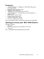
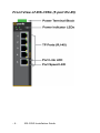
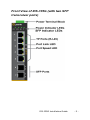
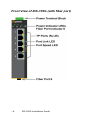
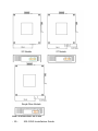
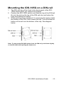
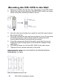
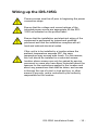
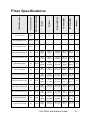
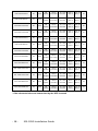
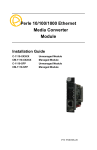
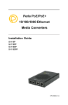
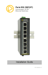
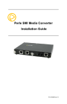
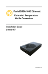
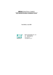
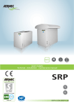
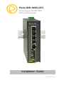
Perle IDS-105G (XT)
Unmanaged 10/100/1000
Ethernet Switches
Installation Guide
P/N 5500340-10
Overview
This document contains instructions necessary for the installation
and operation of the Perle IDS-105G Ethernet switch. This
Ethernet switch can be ordered as a 5-port RJ-45 switch or as a 5port RJ-45 switch with either one fiber port (SC or ST) or up to two
SFP transceiver ports. The fiber port can be either single mode
(SM) or multimode (MM) depending on the model selected and
they can operate over different wavelengths and distances. The
SPF transceiver ports support SFP’s supplied by Perle, Cisco or
other manufacturers of MSA complaint SFP modules.
Visit the Perle website for the most up to date installation guides,
models and specifications. http://www.perle.com/
Model
Port 1-5
Port 6
Port 7
IDS-105G
TP (RJ-45)
None
None
IDS-105G-xxxxxxxx
TP (RJ-45)
Fiber port
Not applicable
IDS-105G-SFP
TP (RJ-45)
IDS-105G-DSFP
TP (RJ-45)
IDS-105G-XT
(Industrial
Temperature)
TP (RJ-45)
IDS-105G-SFP-XT
TP (RJ-45)
IDS-105G-DSFP-XT
TP (RJ-45)
IDS-105G-xxxxxxxx-XT
(Industrial
Temperature
TP (RJ-45)
SFP
transceiver
port *
SFP
transceiver
port *
None
SFP
transceiver
port*
SFP
transceiver
port*
Fiber port
Not applicable
SFP
transceiver
port*
None
Not applicable
SFP
transceiver
port*
Not applicable
Note: xxxxxxxx indicates models numbers for this product line.
TP = twisted pair
* fiber characteristics are determined by the SFP inserted
-2-
IDS-105G Installation Guide
Features
•
•
•
•
•
•
•
•
•
10/100/1000Base-T, 1000Base-X, SC/ST/SFP fiber ports,
multi/single mode
Pluggable SFP transceiver ports
IEEE 802.3/802.3u/802.3x
1000Base-SX /LX/LH /BX-U/BX-D /EX /ZX
10/100/1000Base-T, Full/Half duplex, Auto-negotiation on
copper ports
Redundant DC power inputs
Rugged high-strength case
Industrial temperature models
Din-rail or wall/panel mounting
Note – In this guide the various models will be referred to as the IDS-105G
Getting to know your IDS-105G Switch
Package Contents:
•
•
•
IDS-105G
DIN-rail mounting clip (pre-installed on the unit)
This guide
Note – optional panel/wall mounting kits may be ordered
IDS-105G Installation Guide
-3-
Front View of IDS-105G (5 port RJ-45)
-4-
IDS-105G Installation Guide
Front View of IDS-105G (with two SFP
transceiver ports)
IDS-105G Installation Guide
-5-
Front View of IDS-105G (with fiber port)
-6-
IDS-105G Installation Guide
Bottom view of the IDS-105G (with fiber
port)
Top view of the IDS-105G
Power
The IDS-105G switch has two power inputs that can be connected
simultaneously to DC or AC power sources. See Top view of the
IDS-105G for location. If one power source fails, the other acts as
a backup, and automatically powers the switch. See Connecting
Power to the IDS-105G for information on how to connect power.
Reset Button
To reset the IDS-105G insert a paper clip into the air hole vent
(see Top view of the IDS-105G for location) and gently press the
reset button. The LEDs on the IDS-108F will go On and then
momentarily Off when released to show that the unit has been
reset. All links will be dropped and the MAC tables will be cleared.
IDS-105G Installation Guide
-7-
LED Status
P1 / P2– Power (Green LED)
On: Power present
Off: No Power Present
6 (Port 6 – Fiber or SFP) (Green LED)
On: Link up
Flashing: Link up and Ethernet activity detected
Off: Link down
7 (Port 7 – SFP) (Green LED)
On: Link up
Flashing: Link up and Ethernet activity detected
Off: Link down
Port Link (Green and/or Yellow LED)
On: Link up
Flashing: Link up and Ethernet activity detected
Off: Link Down
Port Speed (Green and Yellow LED)
1000 Mbps:Green On; Yellow Off
100 Mbps:Green On; Yellow On
10 Mbps:Green Off; Yellow On
-8-
IDS-105G Installation Guide
Views for the IDS-105G
Note: all dimensions are in mm
IDS-105G Installation Guide
-9-
Note: all dimensions are in mm
- 10 -
IDS-105G Installation Guide
Mounting the IDS-105G on a DIN-rail
1. The DIN-rail clip will be fixed to the back panel of the IDS105G switch when you receive the product.
2. Position the IDS-105G switch such that the top of the DIN-rail
fits into the slot on the top of the DIN-rail clip, just below the
hook and behind the spring.
3. While pushing down on the unit to compress the spring rotate
the bottom of the IDS-105G toward the rail. This will snap the
bottom of the rail into the bottom of the clip. See diagram
below.
Note: To remove the IDS-105G switch from the DIN-rail, push down slightly
on the IDS-105G while pulling the bottom out.
IDS-105G Installation Guide
- 11 -
Mounting the IDS-105G to the Wall
1. Remove the DIN-rail clip from the rear panel on the IDS-105G.
2. Attach the wall mount plates to the IDS-105G switch as shown
below using the screws provided in the kit.
3. Use the wall mount plates as a guide to mark the spots where
the screws will be.
4. Drive the screws into the wall leaving about 2 mm of the screw
protruding from the wall to allow room for sliding the wall
mount panel between the wall and the screws.
5. Once the screws are fixed to the wall, insert the four screw
heads through the large parts of the keyhole shaped screw
openings.
6. Pull the IDS down to lock the IDS-105G to the wall mount.
7. Tighten the four screws securely to the wall.
Note: For the best results use screws that have the following attributes:
Head diameter .5 - .6 mm
Shaft diameter 3 - 3.5 mm
Note: the dimensions are in mm
- 12 -
IDS-105G Installation Guide
Wiring up the IDS-105G
Power sources must be off prior to beginning the power
connection steps.
Ensure that the voltage and current ratings of the
intended power source are appropriate for the IDS105G as indicated on the product label.
Ensure that the installation and electrical wiring of the
equipment is performed by trained and qualified
personnel and that the installation complies with all
local and national electrical codes.
If this unit is to be installed in a location where the
ambient temperature exceeds 50C, the case
temperature may exceed safe levels. For this reason,
this unit should be installed in a restricted access
location where access can only be gained by service
personnel or users who have been instructed about the
reasons for the restrictions applied to the location and
about any precautions that shall be taken; and access
is through the use of a tool or lock and key, or other
means of security, and is controlled by the authority
responsible for the location.
IDS-105G Installation Guide
- 13 -
Connecting the IDS-105G to ground
If your installation requires additional grounding follow this
procedure.
1. Follow the manufacturer’s instructions for attaching the ground
wire to grounding lug.
2. Attach the grounding lug to the chassis and secure with the
grounding screw provided.
Grounding the chassis requires the following items:
•
•
One grounding lug (not provided)
One 18-12 AWG wire (not provided)
Connecting Power to the IDS-105G
1. Ensure the power source is off prior to connection.
th
2. Strip both wires 5 mm (3/16 inch).
3. Loosen the terminal block screws and connect positive (+) /
negative (-) wires into the -/+ terminals.
4. Tighten terminals screws (0.22Nm-0.25Nm torque).
5. Ensure the wires are securely fastened.
6. Re-insert the Terminal block connector if removed.
7. Turn on power source.
8. Check that the P1 LED is On.
9. If desired connect P2 (power source 2, beginning at Step 1).
- 14 -
IDS-105G Installation Guide
Ethernet Copper Cabling Requirements
•
•
•
Category 5 UTP or STP
24-22 AWG
Straight through or Ethernet crossover cable
Connect the copper cables from each TP port (RJ-45) on the IDS105G switch to Ethernet-enabled devices. See below for pinouts.
8-pin RJ-45
Remaining pins not used.
Fiber Port Cabling Requirements
MM: 50/125 microns or 62.5/125 microns
SM: 9/125 microns
Connect the fiber cables to Port 6/7 on the IDS-105G and the
other end to a compliant fiber devices. If you are making your own
fiber cables, remember that the RX on one side needs to go to TX
on the other side and vice versa. See diagram below.
RX
RX
TX
TX
IDS-105G Installation Guide
- 15 -
Technical Specifications
Connection
Dual input terminal block power
Reverse Polarity Protection
Power Input/Consumption
9.6 to 60 VDC, 1.25Amax
18 to 30 VAC, 0.67A max
Yes
Interface
RJ-45
10/100/1000Base-T, auto negotiation
speed, F/H duplex mode and auto
MDI/MDI-X connection
Fiber Ports
1000Base-X (SC or ST connectors)
SFP transceiver ports
One or two transceiver ports (depending
on model) for 1000Base-X SFP’s
LED indicators
P1 – power 1
P2 – power 2
Ports 1 – 8 G/Y –Link/Activity/Speed
Port 6 – port status (Fiber or SFP models)
Port 7 – port status (SFP models)
Environmental
Operating Temperature
Commercial Models
Industrial Models
0°C to 60°C (32°F to 140°F)
-40°C to 75°C (-40°F to 167°F)
Storage Temperature
Commercial Models
Industrial Models
-25°C to 70°C (-13°F to 158°F)
-40°C to 85°C (-40°F to 185°F)
Operating Humidity
5% to 90% non-condensing
Storage Humidity
5% to 95% non-condensing
Operating Altitude
Up to 3,048 m (10,000 ft)
Regulatory Approvals
Safety
cUL 60950-1, EN 60950-1
Industrial
UL 508
Hazardous Locations
ANSI/ISA 12.12.01-20xx Class I Division 2
Groups A-D - Pending
ATEX Class I Zone 2 - Pending
Laser Safety
Transmitters: EN60825-1:2007
FDA/CDRH 21
CFR1040.11/CFR1040.11
EMI/EMC
FCC Part 15 – Class B
CISPR22 / EN55022 Class B
EN55024 Class B
- 16 -
IDS-105G Installation Guide
None
IDS-105G-DSFP* (XT)
n/a
n/a
n/a
n/a
n/a
one
-
-
-
-
-
-
None
two
-
-
-
-
-
-
IDS-105G-M2SC05 (XT)
SC
None
MM
duplex
550 m
1804 ft
TX: 850
RX:850
Min:-9.5
Max:-4
Min:-17
Max:-3
7.5
IDS-105G-M2ST05 (XT)
ST
None
MM
duplex
550 m
1804 ft
TX: 850
RX:850
Min:-9.5
Max:-4
Min:-17
Max:-3
7.5
IDS-105G-M2SC2
SC
None
MM
duplex
2 km
1.2 miles
TX: 1310
RX:1310
Min:-6
Max:0
Min:-17
Max:-3
11
IDS-105G-M2ST2
ST
None
MM
duplex
2 km
1.2 miles
TX: 1310
RX:1310
Min:-6
Max:0
Min:-17
Max:-3
11
IDS-105G-S2SC10 (XT)
SC
None
SM
duplex
10 km
6.2 miles
TX: 1310
RX:1310
Min:-9.5
Max:-3
Min:-20
Max:-3
10.5
IDS-105G-S2ST10 (XT)
ST
None
SM
duplex
10 km
6.2 miles
TX: 1310
RX:1310
Min:-9.5
Max:-3
Min:-20
Max:-3
10.5
IDS-105G-S1SC10U-XT
SC
None
SM
duplex
10 km
6.2 miles
TX: 1310
RX:1490
Min:-9
Max:-3
Min:-20
Max:-3
11
IDS-105G-S1SC10D-XT
SC
None
SM
duplex
10 km
6.2 miles
TX: 1490
RX:1310
Min:-9
Max:-3
Min:-20
Max:-3
11
IDS-105G-S1SC20U
SC
None
SM
duplex
20 km
12.4 miles
TX: 1310
RX1490
Min:-8
Max:-3
Min:-22
Max:-3
14
IDS-105G-S1SC20D
SC
None
SM
duplex
20 km
12.4 miles
TX: 1490
RX:1310
Min:-8
Max:-3
Min:-22
Max:-3
14
IDS-105G Installation Guide
Budget
RX Power (dB)
n/a
TX Power (dB)
Wavelength (nm)
IDS-105G-SFP* (XT)
Distance
None
Mode
Fiber Connector
IDS-105G (XT)
SFP transceiver ports
IDS-105G models
Fiber Specifications
- 17 -
IDS-105G-S2SC40
SC
None
SM
duplex
40 km
24.9 miles
TX: 1310
RX:1310
Min:-3
Max:-5
Min:-23
Max:-3
20
IDS-105G-S2ST40
ST
None
SM
duplex
40 km
24.9 miles
TX: 1310
RX:1310
Min:-3
Max:-5
Min:-23
Max:-3
20
IDS-105G-S1SC40U
SC
None
SM
duplex
40 km
24.9 miles
TX: 1310
RX:1490
Min:-3
Max:-2
Min:-23
Max:-3
20
IDS-105G-S1SC40D
SC
None
SM
duplex
40 km
24.9 miles
TX: 1490
RX:1310
Min:-3
Max:-2
Min:-23
Max:-3
20
IDS-105G-S2SC70
SC
None
SM
duplex
70 km
43.5 miles
TX: 1550
RX:1550
Min:-2
Max:5
Min:-23
Max:-3
21
IDS-105G-S2ST70
ST
None
SM
duplex
70 km
43.5 miles
TX: 1550
RX:1550
Min:-2
Max:5
Min:-23
Max:-3
21
IDS-105G-S1SC80U
ST
None
SM
simplex
80 km
49.7 miles
TX: 1510
RX:1590
Min:-2
Max:3
Min:-26
Max:-3
24
IDS-105G-S1ST80D
ST
None
SM
simplex
80 km
49.7 miles
TX: 1590
RX:1510
Min:-2
Max:3
Min:-26
Max:-3
24
IDS-105G-S2SC120
SC
None
SM
duplex
120 km
74.6 miles
TX: 1550
RX:1550
Min:0
Max:5
Min:-32
Max:-9
32
IDS-105G-S1SC120U
SC
None
SM
simplex
120 km
74.6 miles
TX: 1510
RX:1590
Min:-2
Max:3
Min:-26
Max:-3
24
IDS-105G-S1SC120D
ST
None
SM
simplex
120 km
74.6 miles
TX: 1590
RX:1510
Min:-2
Max:3
Min:-26
Max:-3
24
IDS-105G-S2SC160
SC
None
SM
duplex
160 km
100 miles
TX: 1550
RX:1550
Min:0
Max:5
Min:-32
Max:-9
32
IDS-105G-S2ST160
ST
None
SM
duplex
160 km
100 miles
TX: 1550
RX:1550
Min:0
Max:5
Min:-32
Max:-9
32
* fiber characteristics are determined by the SFP inserted
- 18 -
IDS-105G Installation Guide
Contacting Technical Support
Contact information for the Perle Technical Assistance Center (PTAC)
can be found at the link below. A Technical Support Query may be made
via this web page.
www.perle.com/support_services/support_request.shtml
Warranty / Registration
This product is covered by the Perle Ethernet Switches Warranty.
Details can be found at:
http://www.perle.com/support_services/warranty.shtml
Copyright © 2014 Perle Systems Limited all rights reserved. No part of
this document may be reproduced or used in any form without written
permission from Perle Systems Limited.
IDS-105G Installation Guide
- 19 -