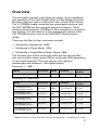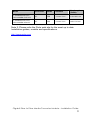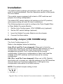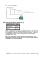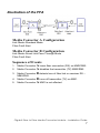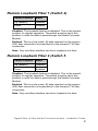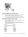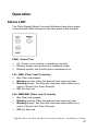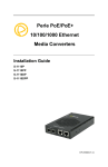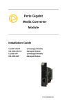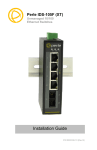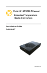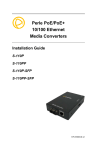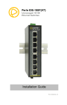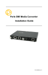
1
Perle Gigabit
Fiber to Fiber
Media Converter
Module
Installation Guide
C-1000MM-XXXXXX
CM-1000MM-XXXXXX
Unmanaged Module
Managed Module
P/N 5500315-10
Overview
This document contains instructions necessary for the installation
and operation of the Perle Gigabit Fiber to Fiber Media Converter
Module(s) that are used in conjunction with a Perle MCR chassis.
The C-1000MM media converters are unmanaged modules, and
the CM-1000MM are the managed converter modules. These
products allow dissimilar 1000Base-X fiber interfaces to connect to
one another. For information on the management options of the
CM-1000MM module, refer to the MCR-MGT Module User’s
Guide.
These are the fiber to fiber conversion models:
• Multimode to Multimode (MM)
• Multimode to Single Mode (SM)
• Multimode to Single Mode Single Strand (MM)
The first fiber port will be multimode (MM) and the second fiber
port can be either single mode (SM) or multimode (MM) depending
on the model selected. They can operate over different
wavelengths and distances. (See tables below).
Fiber port 1 – MM1
Model
Connector
Mode
Distance
Wavelength
(TX/RX)
All models
SC/ST/LC
MM.
550 m/1804 ft.
850 nm
Fiber port 2 – MM2/SM2
Model
Connector
Mode
Distance
Wavelength
(TX/RX)
C-1000MM-M2xx05
CM-1000MM-M2xx05
SC/ST/LC
MM
550 m/1804 ft.
850 nm
C-1000MM-S2xx10
CM-1000MM-S2xx10
SC/ST/LC
SM
10 km/6.2 mi.
1310 nm
C-1000MM-S2xx40
CM-1000MM-S2xx40
SC/ST/LC
SM
40 km/24.9 mi.
1310 nm
C-1000MM-S2xx70
CM-1000MM-S2xx70
SC/ST/LC
SM
70 km/43.5 mi.
1550 nm
C-1000MM-S2xx120
CM-1000MM-M2xx05
SC/ST/LC
SM
40 km/24.9 mi.
1550 nm
Gigabit Fiber to Fiber Media Converter Module – Installation Guide
2
Model
Connector
Mode
Distance
Wavelength
(TX/RX)
C-1000MM-S1SC10U
CM-1000MM-S1SC10U
SC
SM
10 km/6.2 mi.
1310/1490 nm
C-1000MM-S1SC10D
CM-1000MM-M2xx05
SC
SM
10 km/6.2 mi.
1490/1310 nm
Note 2: Please refer the Perle web site for the most up to date
Installation guides, models and specifications.
http://www.perle.com/
Gigabit Fiber to Fiber Media Converter Module – Installation Guide
3
Installation
The default switch settings (all switches in the UP position) will
work for most installations. See the Operation section of this guide
for more details.
The module comes equipped with a bank of DIP switches and
jumpers for setting configuration
The default DIP switch settings (all switches in the UP position)
and jumper setting will work for most installations.
The following steps are used to configure the Perle Gigabit Fiber
to Fiber Media Converter Module:
1. Set the Auto-Config jumper. (CM-1000MM only) (optional)
2. Set the DIP switch settings (optional).
3. Insert the Media Converter Module into the chassis.
4. Connect the fiber cables.
Auto-Config Jumper (CM-1000MM only)
The Auto-Config jumper is J5.
Refer to the diagram below for labelling.
Auto (Pin 2 and Pin 3 are strapped): When set to Auto the
module will, at power-up, check its internal flash memory to see if
configuration information has been downloaded to it from a
management module. If so, it will use this as its running
configuration. If there is no configuration in flash it will read the
settings of the DIP switches and use those as its running
configuration.
SW: (Pin 1 and Pin 2 are strapped): When set to SW (Switch),
the module will, at power-up, read the settings of the DIP Switches
and use those as it running configuration. It will ignore any
configuration information in its flash memory.
NOTE: The default jumper setting is Auto
Gigabit Fiber to Fiber Media Converter Module – Installation Guide
4
DIP Switch Settings
Fiber Negotiation (Switch 1)
Switch Position
Mode
Up (default)
Auto
Down
Off
Auto: In this mode of operation the Media Converter will negotiate
fiber parameters on both MM1and MM2/SM2 (fiber ports). This will
ensure the most optimal connection parameters will be in effect. If
connecting to another Perle media converter, this parameter
should be set to Auto.
Off: Fiber negotiation on both fiber ports will be disabled. Fiber
Negotiation should only be turned off, if the fiber link partner does
not support fiber link negotiations.
Gigabit Fiber to Fiber Media Converter Module – Installation Guide
5
Link Mode (Switch 2)
Switch Position
Mode
Up (default)
Smart Link Pass-Through Mode
Down
Standard Mode
Smart Link Pass-Through: In this mode, the link state on one
connection is directly reflected through the Media Converter to the
other connection. If link is lost on one of the connections, then the
other link will be brought down.
Standard Mode: In this mode the links can be brought up and
down independently of each other. A loss of link on either fiber
connection can occur without affecting the other connection.
Fiber Fault Alert (Switch 3)
Switch Position
Mode
Up (default)
Enabled
Down
Disabled
Enabled: If the media converter module detects a loss of fiber
signal on the fiber receiver, the media module will immediately
disable its fiber transmitter signal on this port. This, in effect,
notifies the fiber link partner that an error condition exists on the
fiber connection.
If the remote media converter module is set up for Fiber Fault
Alert(FFA) Enabled and the local media converter is set up with
Smart Link Pass-Through, a loss of fiber link on either the transmit
or receive line will be passed through to the other fiber connection.
Disabled: The media converter module will not monitor for fiber
fault.
Note: This feature is not required; if Fiber negotiation has been
enabled since link negotiation accomplishes the same thing. When
Fiber Negotiation is enabled this switch is ignored.
Gigabit Fiber to Fiber Media Converter Module – Installation Guide
6
Illustration of the FFA
Media Converter A Configuration
Link Mode–Standard Mode
Fiber Fault Alert
Media Converter B Configuration
Link Mode–Smart Link Pass Through Mode
Fiber Fault Alert
Sequence of Events
1. Media Converter A loses fiber connection (RX) on MM2/SM2.
2. Media Converter A disables the transmitter (TX) MM2/SM2.
3. Media Converter B detects loss of fiber link on receiver RX –
MM2/SM2.
4. Media Converter B turns off transmitter (TX) on MM1.
5. Media Converter A MM1 is not affected
Gigabit Fiber to Fiber Media Converter Module – Installation Guide
7
Remote Loopback Fiber 1 (Switch 4)
Switch Position
Mode
Up (default)
Disabled
Down
Enabled
Disabled: The loopback feature is disabled. This is the normal
position for regular operation. The switch must be set to this
position in order for data to pass through the Media Converter
Module.
Enabled: This is a test mode. All data received on the receive
(RX) fiber connection is looped back to the transmit (TX) fiber
connection.
Note: Only one fiber interface can be in loopback at a time.
Remote Loopback Fiber 2 (Switch 5
Switch Position
Mode
Up (default)
Disabled
Down
Enabled
Disabled: The loopback feature is disabled. This is the normal
position for regular operation. The switch must be set to this
position in order for data to pass through the Media Converter
Module.
Enabled: This is a test mode. All data received on the receive
(RX) fiber connection is looped back to the transmit (TX) fiber
connection.
Note: Only one fiber interface can be in loopback at a time.
Gigabit Fiber to Fiber Media Converter Module – Installation Guide
8
Installing Media Converter Modules
Caution: Observe electrostatic discharge precautions when
installing the Media Converter Module(s) into the Chassis. Failure
to observe this caution could result in damage to the Module(s)
and/or chassis.
The Perle Media Converter Modules can be installed in any
available slot and in any order within the chassis.
1. Remove the Module from its packaging.
2. Using a cross-head screwdriver, remove the screw holding the
face plate to the Chassis to reveal the slot opening.
3. Set the jumpers and DIP switches on the Media Converter
Module to the desired operating mode.(optional)
4. Locate the top and bottom alignment guides inside the MCR
Chassis.
5. Using the module alignment guides gently slide the module
into the slot until it becomes flush with the front of the Chassis.
Light pressure may be needed to seat the module. Do not
force the module as you might cause damage. If there is
resistance, remove the module and check the module
connector for damaged or incorrectly aligned pins. If these are
not damaged, retry module insertion.
6. Tighten the captive retainer screw to ensure the Media
Converter Module is locked in place.
7. Remove the dust cap from the fiber connector and connect the
fiber and copper cables.
Gigabit Fiber to Fiber Media Converter Module – Installation Guide
9
Removing Media Convert Modules
1. Loosen the captive retainer screw on the front of the Media
Converter Module and gently pull the module out.
2. If not inserting a replacement Media Converter Module then
cover the opening slot with a face plate and secure the screw.
Installing the Duplex Fiber Cable
1. Locate a 1000Base-X compliant duplex (2 strands) fiber cable
with appropriate connectors.
2. Connect the fiber cables from one Converter to the other
Converter/switch/fiber device ensuring that the RX and TX are
reversed at the opposite end.
Gigabit Fiber to Fiber Media Converter Module – Installation Guide
10
Installing the Simplex Fiber Cable
1. Locate a 1000Base-X compliant simplex (1 strand) fiber cable
with appropriate connectors.
2. Connect the fiber cable from one Converter to the other
Converter/switch/fiber device.
Gigabit Fiber to Fiber Media Converter Module – Installation Guide
11
Operation
Status LED
The Perle Gigabit Media Converter Modules have three single
colored status LEDs located on the face plate of the module.
PWR - Power/Test
•
•
•
On: Power is on, module is operating normally.
Blinking slowly: the module is in loopback mode.
Blinking quickly: the module has a hardware error.
LK1- MM1 (Fiber Link10) Activity
•
•
•
•
On: Fiber link present.
Blinking quickly: Fiber link present and receiving data.
Blinking slowly: The fiber link has been taken down as a
result of Smart Link Pass-Through
Off: No fiber link.
LK2- MM2/SM2 (Fiber Link 2) Activity
•
•
•
•
On: Fiber link present.
Blinking quickly: Fiber link present and receiving data.
Blinking slowly: The fiber link has been taken down as a
result of Smart Link Pass-Through.
Off: No fiber link.
Gigabit Fiber to Fiber Media Converter Module – Installation Guide
12
Troubleshooting
General
•
•
•
•
Ensure the module is securely seated in the chassis. The
PWR LED on the module should be on solid.
Ensure all cabling is of the correct type and is in good
operating condition.
Ensure both devices on either end of the fiber are compatible.
If using a simplex fiber connection, ensure that you have both
an Upstream (U) and Downstream (D) Media Converters.
For dual-stranded fiber connections, ensure the RX and TX
has been reversed between the two Media Converters.
No connectivity
If unable to get full connectivity with all DIP switches in the UP
position, these methods are recommended for troubleshooting.
Method 1
1. Turn off Fiber Negotiation (SW1 Down) on both media
converters. Leave all other switches UP.
2. Connect the near end device to port MM1, the LK1 LED
should be lit to indicate a good fiber connections. If the LK1
LED is not lit, then check the fiber cable and the attached
device.
3. Repeat step 2 for port MM2/SM2.
4. Return the media converter to the desired configuration.
Method 2:
The fiber connection can also be verified by configuring the remote
media converter for loopback mode. The LEDs on both media
converters should be lit. Data should pass through the local
converter then over the fiber connection to the remote media
converter.
Gigabit Fiber to Fiber Media Converter Module – Installation Guide
13
Note: If troubleshooting a CM-1000MM, setting the Auto-Config
jumper (J5) to SW will ensure the DIP switches are being read.
Technical Specifications
The following applies to all C-1000MM and CM-1000MM media
converters:
Power Input/Consumption
Operating Temperature:
Storage Temperature:
Operating Humidity:
Storage Humidity:
Operating Altitude:
Weight:
MTBF: (C-1000MM)
MTBF: (CM-1000MM)
12V DC /2.5 W
0°C - 50°C (32°F - 122°F)
-25°C - 70°C (-13°F - 158°F)
5% to 90% non-condensing
5% to 95% non-condensing
Up to 3,048 m (10,000 ft)
0.15 kg (0.33 lbs)
421,344 hours
417,722 hours
Fiber Optic Specifications:
Fiber port 1 – MM1
Model
C-1000MM-M2SC05
CM-1000MM-M2SC05
Mode
MM
Wave
length
(nm)
TX: 850
RX: 850
TX
Power
(dB)
RX
Power
(dB)
Budget
(dB)
Min: -9.5
Max: -4
Min: -17
Max: -3
7.5
TX
Power
(dB)
RX
Power
(dB)
Budget
(dB)
Fiber port 2 – MM2/SM2
Model
Mode
Wave
length
(nm)
C-1000MM-M2SC05
CM-1000MM-M2SC05
MM
TX: 850
RX: 850
Min: -9.5
Max: -4
Min: -17
Max: -3
7.5
C-1000MM-M2ST05
CM-1000MM-M2ST05
MM
TX: 850
RX: 850
Min: -9.5
Max: -4
Min: -17
Max: -3
7.5
C-1000MM-M2LC05
CM-1000MM-M2LC05
MM
TX: 850
RX: 850
Min: -9.5
Max: -4
Min: -17
Max: -3
7.5
C-1000MM-S2SC10
CM-1000MM-S2SC10
SM
TX: 1310
RX:1310
Min: -9.5
Max: -3
Min: -20
Max: -3
10.5
C-1000MM-S2ST10
CM-1000MM-S2ST10
SM
TX: 1310
RX:1310
Min: -9.5
Max: -3
Min: -20
Max: -3
10.5
Gigabit Fiber to Fiber Media Converter Module – Installation Guide
14
C-1000MM-M2LC10
CM-1000MM-M2LC10
SM
TX: 1310
RX:1310
Min: -9.5
Max: -3
Min: -20
Max: -3
10.5
C-1000MM-S2SC40
CM-1000MM-S2SC40
SM
TX: 1310
RX:1310
Min: -3
Max: 5
Min: -23
Max: -3
20
C-1000MM-S2ST40
CM-1000MM-S2ST40
SM
TX: 1310
RX:1310
Min: -3
Max: 5
Min: -23
Max: -3
20
C-1000MM-S2LC40
CM-1000MM-S2LC40
SM
TX: 1310
RX:1310
Min: -3
Max: 2
Min: -23
Max: -3
20
C-1000MM-S2SC70
CM-1000MM-S2SC70
SM
TX: 1550
RX:1550
Min: -2
Max: 5
Min: -23
Max: -3
21
C-1000MM-S2ST70
CM-1000MM-S2ST70
SM
TX: 1550
RX:1550
Min: 0
Max: 5
Min: -23
Max: -3
23
C-1000MM-S2LC70
CM-1000MM-S2LC70
SM
TX: 1550
RX:1550
Min: 0
Max: 5
Min: -23
Max: -3
23
C-1000MM-S2SC120
CM-1000MM-S2SC120
SM
TX: 1550
RX:1550
Min: 0
Max: 5
Min: -32
Max: -9
32
C-1000MM-S2ST120
CM-1000MM-S2ST120
SM
TX: 1550
RX:1550
Min: 0
Max: 5
Min: -32
Max: -9
32
C-1000MM-S2LC120
CM-1000MM-S2LC120
SM
TX: 1550
RX:1550
Min: 0
Max: 5
Min: -32
Max: -9
32
C-1000MM-S1SC10U
SM
CM-1000MM-S1SC10U
TX: 1310
RX:1490
Min: -9
Max: -3
Min: -20
Max: -3
11
C-1000-S1SC10D
CM-1000-S1SC10D
TX:1490
RX:1310
Min: -9
Max: -3
Min: -20
Max: -3
11
SM
Fiber Cabling Requirements:
MM: 50/125 microns or 62.5/125 microns
SM:
9/125 microns
Note: Please refer the product page on the Perle website for the
most up to date models and specifications.
http://www.perle.com/
Gigabit Fiber to Fiber Media Converter Module – Installation Guide
15
Compliance Information
FCC
This product has been found to comply with the limits for a Class A digital device,
pursuant to Part 15 of the FCC rules. These limits are designed to provide
reasonable protection against harmful interference when the equipment is operated
in a commercial environment. This equipment generates, uses, and can radiate
radio frequency energy and, if not installed and used in accordance with the
instructions in this Guide, may cause harmful interference to radio communications.
Operation of this equipment in a residential area is likely to cause harmful
interference, in which case the user will be required to correct the interference at
his/her own expense.
EN 55022, Class A,
WARNING This is a Class A product. In a domestic environment this product may
cause radio interference in which case the user may be required to take adequate
measures.
EN 55024, Class A
Laser Safety – IEC 60825-1:2007
This product meets Class I Laser safety requirements per IEC-60825-1:2007
standard and complies with FDA/CDRH 21 CFR1040.10 and 21 CFR1040.11.
WARNING: Visible and invisible laser radiation may be present when cables are
not connected. Do not stare into the beam or view the beam directly with optical
instruments. Failure to observe this warning could result in an eye injury or
blindness.
WARNING: Use of controls, adjustments or the performance of procedures other
than those specified herein may result in hazardous radiation exposure.
Gigabit Fiber to Fiber Media Converter Module – Installation Guide
16
Warranty / Registration
Perle’s standard Lifetime Warranty provides customers with return
to factory repairs for Perle products that fail under the conditions of
the warranty coverage. Details can be found at:
http://www.perle.com/support_services/warranty.shtml
Contacting Technical Support
Contact information for the Perle Technical Assistance Center
(PTAC) can be found at the link below. A Technical Support Query
may be made via this web page.
www.perle.com/support_services/support_request.shtml
Copyright
© 2011 Perle Systems Limited
All rights reserved. No part of this document may be reproduced or used in any form
without written permission from Perle Systems.
Gigabit Fiber to Fiber Media Converter Module – Installation Guide
17