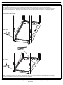
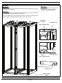
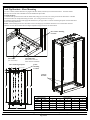
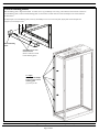
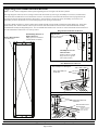
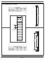
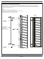
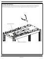
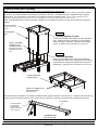
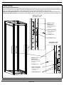
1
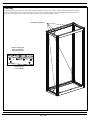
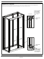
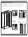
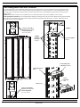
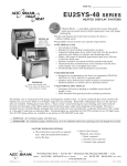
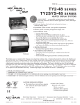
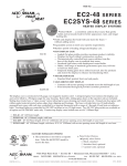
NET-SERV Cabinets INSTRUCTIONS CM408F © Panduit Corp. 2009-2011 FOR TECHNICAL SUPPORT www.panduit.com/resources/install_maintain.asp Page 1 of 24 INSTRUCTIONS CM408F TableofContentsͲNetͲSERVCabinets CabinetOperation Page AccessoryGuide .. ... 3 Leveling . ... 4 Ganging .. 5 AntiͲTipBracketsͲFloorMounting .. 6 Grounding . 7 EquipmentRailAdjustment 8 CableManagementBracketsandFingers 9 CableManagementPanelandLͲRetainers 10 VerticalBlankingPanels 11 SingleHingeDoor 12 SingleHingeDoorHandleDirectionReversal 13 SplitDoors 14 SidePanelInstallation . 15 POUMountingBrackets 16 POUMountingBracketLocations 17 VerticalPatchPanelBracketInstallation 18 OverheadCableOpenings . 19 VerticalExhaustDuctMounting . 20 CabinetSealing 21Ͳ23 NOTES: Casters can support a fully loaded cabinet. However, the casters should only be used to move the cabinet from one location to another. To ensure maximum stability, the leveling legs should be used to support the cabinet when it is in the permanent location. Not all features are included with all Net-SERV configurations. For Technical Support: www.panduit.com/resources/install_maintain.asp Page 2 of 24 INSTRUCTIONS CM408F Accessory Guide Cabinet Side Panel (S22PS, S52PS) Cage Nut Equipment Rails and Brackets (S62RC, S65RC, S72RC, S75RC) Casters (SCSTR) Vertical Patch Panel Bracket (SVPPB) POU Brackets (SVPDUB) [6] L-Fingers and [1] CMSRC2 are included per panel Cable Management Finger Bracket and Fingers (S62BRFK, S65BRFK, S72BRFK, S75BRFK) Cable Management Panel and L-Retainers (S62BRCK, S65BRCK, S72BRCK, S75BRCK) For Technical Support: www.panduit.com/resources/install_maintain.asp Page 3 of 24 INSTRUCTIONS CM408F Leveling With the leveling legs fully retracted, use two people to slide the cabinet into the desired location. Lower the leveling legs using a 3/8” (10mm) deep well socket, until the cabinet weight is fully supported. Use a bubble level placed on the base rails in the locations shown to adjust legs until the cabinet is level. For ganged cabinet applications, ensure that adjacent cabinets are adjusted to the same height, parallel with each other, and no gaps at the top or bottom between cabinets. Front-to-Back Cabinet Leveling 3/8” socket Side-to-Side Cabinet Leveling 3/8” socket Note: The maximum weight load of the cabinet is 2500 pounds (1134 kg). The weight load should be evenly distributed across the height of the cabinet, with the heaviest components mounted at the bottom of the cabinet. For Technical Support: www.panduit.com/resources/install_maintain.asp Page 4 of 24 INSTRUCTIONS CM408F Ganging IMPORTANT: If side panels are going to be used between cabinets, install (if needed) prior to ganging cabinets as shown on page 15. IMPORTANT: Ensure tops of cabinets are touching prior to ganging. Do not cinch the cabinets together with the ganging hardware. IMPORTANT: Ensure cabinets are level by following the guidelines on page 4. Leveling the cabinet prior to ganging is important to ensure proper door operation. Secure the cabinets with two (2) top ganging brackets and (2) bottom ganging brackets with two (2) #10-32 trilobular screws per bracket in the locations shown. Top Ganging Location Ganging Bracket #10-32 Trilobular Screw Ganging Bracket #10-32 Trilobular Screw 600mm/700mm Spacing 24” Spacing Bottom Ganging Location For Technical Support: www.panduit.com/resources/install_maintain.asp Page 5 of 24 INSTRUCTIONS CM408F Anti-Tip Brackets - Floor Mounting NET-SERV Cabinets, whether stand alone or ganged with other cabinets, must always be anchored to the floor. The frame anchors directly to the concrete slab or threaded rod via the included anti-tip brackets. Assembly Sequence 1. Install the anti-tip brackets to the inside of cabinet frame, using (2) 5/16” bolts (1/2” socket) per bracket as shown below. Brackets are slotted to allow for raising and lowering of cabinet. (See leveling instructions on Page 4) 2. Attach the anchors to the floor with appropriate hardware for your type of floor. See Floor Anchoring Footprint view and chart below for floor mounting dimensions. NOTE: Floor mounting bracket to be used when casters or leveling legs are installed. Bracket is to be reversed when casters are installed. Reverse side of bracket allows for higher adjustment range with casters on cabinet frame. Floor Anchor Mounting Locations Anti-Tip Bracket (Bracket to be reversed when casters are installed) 5/16” Bolts (use 1/2” socket) Floor Anchoring Footprint D Frame Mounting Locations 4.0” [102mm] 3.2” [82mm] Anti-Tip Brackets C E B Cabinet Dimensions Width Depth 10.5” [267mm] A A B Mounting Distances C D E 9.8" [250mm] 45.2" [1148mm] 23.6" [600mm] 47.2" [1200mm] 23.6" [600mm] 47.2" [1200mm] 40.7" [1035mm] 27.6" [700mm] 47.2" [1200mm] 27.6" [700mm] 47.2" [1200mm] 40.7" [1035mm] 11.8" [300mm] 45.2" [1148mm] 23.6" [600mm] 39.3" [1000mm] 23.6" [600mm] 39.3" [1000mm] 33.6" [853mm] 9.8" [250mm] 37.3" [947mm] 27.6" [700mm] 39.3" [1000mm] 27.6" [700mm] 39.3" [1000mm] 33.6" [853mm] 11.8" [300mm] 37.3" [947mm] For Technical Support: www.panduit.com/resources/install_maintain.asp Page 6 of 24 INSTRUCTIONS CM408F Grounding The grounding locations for connection to the CBN (Common Bonding Network) are shown below. Remove masking from desired grounding location (see detail below). Attach grouding lug with (2) #12-24 screws. Grounding jumpers are pre-installed between cabinet frame and rear split doors and are included in all NET-SERV configurations that ship with split doors installed on cabinet. Grounding Lug Locations Remove masking and attach grounding lug with 2) #12-24 screws Grounding Lug Location Detail For Technical Support: www.panduit.com/resources/install_maintain.asp Page 7 of 24 INSTRUCTIONS CM408F Equipment Rail Adjustment Loosen (2) 5/16” bolts at top of equipment rail bracket and (2) 5/16” bolts at bottom of equipment rail bracket to release clamping pressure to allow for front to back rail adjustment. Reposition rails and tighten (4) 5/16” bolts to 14ft.-lbs (19.0 N-m). Top Location Loosen (2) 5/16” Bolts to release clamping pressure for front to back rail adjustment (use 1/2” socket) Equipment Rail Bracket Equipment Rail Bracket Bottom Location For Technical Support: www.panduit.com/resources/install_maintain.asp Page 8 of 24 Loosen (2) 5/16” Bolts to release clamping pressure for front to back rail adjustment (use 1/2” socket) INSTRUCTIONS CM408F Cable Management Brackets and Fingers For precise positioning adjustment of cable management brackets, loosen (2) #12-24 hex head screws at top of bracket and (2) #12-24 hex head screws at bottom of bracket using 5/16” socket. Adjust bracket position and retighten (4) #12-24 hex head screws. For large adjustments, remove (4) #12-24 screws securing bracket to cabinet frame, reposition bracket, and secure cable management bracket with (4) #12-24 hex head screws as shown. Cable management fingers may be placed where desired by inserting the tabs on the rear of the finger sections into the mounting slots located on the cable management brackets and then sliding downward. Reverse the process to remove cable management fingers. Loosen (2) #12-24 Hex Head Screws for precise bracket adjustment (use 5/16” socket) Loosen (2) #12-24 Hex Head Screws for precise bracket adjustment (use 5/16” socket) Remove (4) #12-24 Hex Head Screws (2-top, 2 bottom) for large cable management bracket adjustments (use 5/16” socket) Cable Management Finger Bracket For Technical Support: www.panduit.com/resources/install_maintain.asp Page 9 of 24 Cable Management Finger INSTRUCTIONS CM408F Cable Management Panel and L-Retainers For precise adjustment of cable management channel, loosen (2) #12-24 hex head screws at top of channel and (2) #12-24 hex head screws at bottom of channel using 5/16” socket. Adjust channel position and retighten (4) #12-24 hex head screws. For large adjustments, remove (4) #12-24 screws securing channel to cabinet frame, reposition channel, and secure cable management channel with (4) #12-24 hex head screws as shown. -CMSRC2 bend radius control clip can be installed in any of (6) indicated locations with (2) #12-24 Phillips screws as shown. -Cable Management L-Retainers are to be installed where desired by inserting the tab on the rear of the L-Retainer into any keyed mounting slot located on the cable management panel and then sliding downward while pulling release tab forward, as shown. Pull release tab and reverse the process to remove L-Retainers. CMSRC2 Loosen (2) #12-24 Hex Head Screws for precise bracket adjustment (use 5/16” socket) CMSRC2 Mounting Locations (6 Places) (2) #12-24 Phillips Screws Cable Management L-Retainer (installed) Cable Management Panel Keyed Mounting Slot Release Tab Loosen (2) #12-24 Hex Head Screws for precise bracket adjustment (use 5/16” socket) For Technical Support: www.panduit.com/resources/install_maintain.asp Page 10 of 24 INSTRUCTIONS CM408F Vertical Blanking Panels Bottom blanking panel is shipped uninstalled. To install, remove [1] #10 Phillips screw and [1] #10 lockwasher from each side at bottom of vertical blanking panels. Position bottom blanking panel over base frame of cabinet and secure with #10 Phillips screws and lockwashers as shown below. To adjust depth of vertical blanking panels, loosen (6) #10 Phillips screws on each vertical panel, adjust panels to desired depth and retighten (12) #10 Phillips screws. Bottom Blanking Panel #10 Phillips Screws and #10 lockwashers (Remove and use to install bottom blanking panel) To Adjust: Loosen (12) #10 Phillips Screws on each vertical blanking panel [6] screws per side For Technical Support: www.panduit.com/resources/install_maintain.asp Page 11 of 24 INSTRUCTIONS CM408F Single Hinge Door Lift door into place and align lower hinge pin with lower door mounting bracket. Align upper hinge pin with upper door mounting bracket. Position door into place and pull down the lever of the spring loaded hinge pin and release lever when door is aligned. Reverse steps to remove the door. Note: Make sure that both pins are fully engaged when door is installed. Upper Door Mounting Bracket Upper Hinge Pin (pull lever down) Lower Hinge Pin Lower Door Mounting Bracket For Technical Support: www.panduit.com/resources/install_maintain.asp Page 12 of 24 INSTRUCTIONS CM408F Single Hinge Door Handle Direction Reversal NOTE: NET-SERV cabinet configurations that ship with Single Hinge Doors are hinged on the left side by default. With single hinge door removed, remove (2) hinge brackets from cabinet frame by removing (2) #10 Phillips screws and (2) #10 lockwashers from each bracket and slide bracket out of cabinet frame as shown. Invert brackets so that bottom-left bracket becomes top-right bracket and top-left bracket becomes bottom-right bracket as shown below. Secure brackets to cabinet post with (2) #10 Phillips screws and (2) #10 lockwashers per bracket. Brackets are to be inserted through upper-most opening of cabinet frame. Reverse door handle orientation by removing cam from door handle assembly and door handle assembly from Single Hinge Door. Rotate door handle assembly 180º. Rotate orienation of cam stop 90º clockwise while door handle cam and hex bolt are removed from handle assembly. Reinstall handle assembly into Single Hinge Door. See ‘Door Handle Direction Reversal’ view below. Remove PANDUIT label from bottom of door and reinstall label centered and 7-1/4” from top of door. Hinge Bracket Installation and Removal Remove Hinge Brackets (See detail view) Reinstall Hinge Brackets on Right Cabinet Post (Hinge point to be orientated towards outside of cabinet) Hinge Bracket (Tab is to be inserted into cabinet frame) #10 Phillips Screws and #10 lockwashers (Remove and use to install hinge bracket on opposite side of cabine frame) Door Handle Direction Reversal Remove Phillips Screw and Bridge Bar Remove Door Handle Cam and Hex Bolt Remove Door Handle, Rotate 180º, and Reinstall Handle Reinstall Phillips Screw and Bridge Bar Reinstall Door Handle Cam and Hex Bolt Rotate Orientation of Cam Stop 90º Clockwise (This allows for door handle to swing in proper direction) FRONT OF CABINET For Technical Support: www.panduit.com/resources/install_maintain.asp Page 13 of 24 INSTRUCTIONS CM408F Split Doors To remove split doors, first disconnect grounding jumper between each door and cabinet frame (grounding jumpers are located near bottom of doors. Close split doors and remove (4) hinge pins (hinges include a safety feature that keeps doors captive unless they are open to 90 ). Open each split door to 90 and slide door away from cabinet and out of hinges. Reverse steps to reinstall split doors. Disconnect (2) Grounding Jumpers Remove (4) hinge pins from split doors With split door open to 90 slide door out of hinges For Technical Support: www.panduit.com/resources/install_maintain.asp Page 14 of 24 INSTRUCTIONS CM408F Side Panel Installation Lift up the side panel at an angle to the cabinet frame and align bottom of the panel to fit between the vertical posts of cabinet frame. Lower the side panel until the mounting hook is seated on the bottom side panel bracket and the panel is resting on the cabinet frame. Rotate the side panel into place until the panel is flush with the cabinet frame and the (2) latches engage. Pull down on the (2) latches to disengage the side panel, then rotate and lift the panel to remove. Install grounding clips as necessary Pull down and release latches Bottom Side Panel Support For Technical Support: www.panduit.com/resources/install_maintain.asp Page 15 of 24 Side Panel Mounting Hook INSTRUCTIONS CM408F POU Mounting Brackets For precise positioning of POU mounting brackets, loosen (2) #12-24 hex head screws at top bracket and (2) #12-24 hex head screws at bottom bracket using 5/16” socket. Adjust bracket positions and retighten (4) #12-24 hex head screws. For large adjustments, remove (2) #12-24 screws securing each bracket to cabinet frame, reposition brackets, and secure each bracket to cabinet frame with (2) #12-24 hex head screws. Tabs on brackets are to be inserted into cabinet frame as shown. NOTE: When reinstalling POU brackets to cabinet, bracket with diamond cutout is to be mounted at top of cabinet. Insert tab into cabinet frame NOTE Diamond cutout on top POU mounting bracket (2) #12-24 Hex Head Screws (use 5/16” socket) (2) #12-24 Hex Head Screws (use 5/16” socket) POU Mounting Bracket Loosen (2) #12-24 Hex Head Screws for precise bracket adjustment (use 5/16” socket) Loosen (2) #12-24 Hex Head Screws for precise bracket adjustment (use 5/16” socket) For Technical Support: www.panduit.com/resources/install_maintain.asp Page 16 of 24 INSTRUCTIONS CM408F POU Mounting Bracket Locations MAX 1 RU [1.75] MIN MAX For Technical Support: www.panduit.com/resources/install_maintain.asp Page 17 of 24 INSTRUCTIONS CM408F Vertical Patch Panel Bracket Installation Position vertical support of vertical patch panel bracket so that it nestles behind flange of finger bracket. Mounting points are located on the outside of finger bracket. Secure vertical patch panel bracket to Net-SERV finger bracket with (2) #12-24 hex head screws into tapped holes of vertical support of vertical patch panel as shown. Screws are to pass through slots in finger bracket to engage vertical patch panel bracket and allow for vertical adjustment of bracket. NOTES -SVPPB to be used with finger bracket only (700mm/28”) -Recommend use with Panduit Pan-Net and Quick-Net (1) Rack Unit Patch Panels -(3) SVPPB may be fitted to a 42 RU (700mm/28”) cabinet -(4) SVPPB may be fitted to a 45 RU (700mm/28”) cabinet Bracket Installed #12-24 Hex Head Screw Vertical Patch Panel Bracket (SVPPB) (Vertical support nestles behind flange of finger rail) #12-24 Hex Head Screw For Technical Support: www.panduit.com/resources/install_maintain.asp Page 18 of 24 INSTRUCTIONS CM408F Overhead Cable Openings Cabinet is equipped with multiple covers and knockouts for cable entry. The bezel inserts can be removed from overhead cable opening bezels by pulling inserts out of position. Bezels can be removed from cabinet top by depressing tabs and pulling out of position. The remaining knockouts can be removed by cutting the (8) tabs with a wire cutter as shown. Additional bezels and bezel inserts are available for purchase. Removable Bezel Inserts Overhead Cable Opening Bezel For Technical Support: www.panduit.com/resources/install_maintain.asp Page 19 of 24 INSTRUCTIONS CM408F Vertical Exhaust Duct Mounting NOTE: For ease of installation, a minimum of (2) persons are suggested for this assembly step. Lift exhaust duct assembly and position on top of cabinet as shown. Align large top flange towards front of cabinet. Secure duct to cabinet with (6) #10 x 1/2” Phillips trilobular screws and (6) #10 lockwashers as shown. Vertical Exhaust Duct is adjustable to allow for tight fit against ceiling. See view below for course and fine duct adjustment instructions (STEPS 1 and 2). Adjacent Vertical Exhaust Ducts can be ganged by securing ganging bracket with (2) #10 x 1/4” long Phillips screws and (2) #10 lockwashers per side as shown. NOTE: Some adjustment to the leveling of the base of cabinet may be required for exhaust duct to align with exhaust ducts of adjacent cabinets. Large Top Flange (align towards front of cabinet) Vertical Exhaust Duct STEP 2 Fine Duct Adjustment (Top Collar) Loosen (4) #10 Phillips screws holding top collar assembly in place. Position top collar so that seals are secure against ceiling and slightly compressed. Retighten (4) #10 Phillips screws. [(2) additional screws and lockwashers are on rear of duct] (6) #10 x 1/2” Phillips Trilobular Screws and #10 lockwashers [(3) additional screws and lockwashers are on rear of duct] STEP 1 Course Duct Adjustment Remove (4) #10 Phillips screws and (4) #10 lockwashers holding upper duct to lower duct. Raise upper duct to desired height and secure using (4) #10 Phillips screws and (4) #10 lockwashers. [(2) additional screws and lockwashers are on rear of duct] Vertical Exhaust Duct Ganging Bracket (2) #10 x 1/4” Phillips Screws and #10 lockwashers (Front and Back) End seal brackets are adjustable to accomodate conditions between ganged cabinets or at the end of a row. Adjust the end seal bracket by loosening (2) #10 nuts per bracket using a 3/8” socket wrench or end wrench. Extend the end seal bracket and retighten (2) #10 nuts. End Seal Bracket Loosen and retighten #10 nuts to adjust end seal bracket Use 3/8” socket wench or 3/8” end wrench UNDERSIDE VIEW OF TOP COLLAR For Technical Support: www.panduit.com/resources/install_maintain.asp Page 20 of 24 INSTRUCTIONS CM408F Cabinet Sealing Adjacent cabinets may be ganged in one of the following conditions (see leveling and ganging instructions on pages 4-5): CABINET WITH NO SIDE PANEL adjacent to CABINET WITH NO SIDE PANEL - Bulb seals of adjacent cabinets firmly contact each other. Use ganging brackets to maintain firm contact of bulb seals (see page 5). CABINET WITH NO SIDE PANEL adjacent to CABINET WITH SIDE PANEL - Bulb seals of cabinet with no side panel rests firmly against side panel of adjacent cabinet. Cut (4) pieces of 3/16” x 1/2” adhesive foam seal to length and attach along flanges in side panel opening of each cabinet where side panel is installed. Apply top seal behind grounding clips. Use ganging brackets to maintain firm contact of bulb seals (see page 5). Side panel must be removed to install foam seals. See Cabinet Post (Section View). CABINET WITH SIDE PANEL adjacent to CABINET WITH SIDE PANEL - Cut (4) pieces of thin adhesive foam seal to length and attach along flanges in side panel opening of each cabinet where side panels are installed. Apply top seal behind grounding clips. Side panels must be removed to install foam seals. See Cabinet Post (Section View). NOTE: SFS-KIT is required for end of row cabinet sealing. CORRECT BULB SEAL ALIGNMENT INCORRECT BULB SEAL ALIGNMENT Cabinet Post (Section View) (4) 3/16” x 1/2” Adhesive Foam Seals (only apply when side panel is used) Top 3/16” x 1/2” Adhesive Foam Seal (apply behind grounding clip) Top Side Panel Seal (Section View) Grounding Clip Flange in Side Panel Opening 3/16” x 1/2” Adhesive Foam Seal (only apply when side panel is installed) For Technical Support: www.panduit.com/resources/install_maintain.asp Page 21 of 24 INSTRUCTIONS CM408F Cabinet Sealing Raise cabinet frame at least 1” above floor using leveling legs (see page 4). Install Front and Rear Floor Seal Brackets with foam seals to cabinet with (2) #10-32 x 1/2” Phillips trilobular screws and paint piercing washers per bracket. Foam seals are to sit under the cabinet frame when installed. Lower and level the cabinet frame to between 1/2” and 1” above floor to maintain a firm seal between cabinet frame and floor. NOTE: SFS-KIT is required for end of row floor sealing. [2] #10-32 x 1/2” Phillips Trilobular Screws and Paint Piercing Washers Floor Seal Bracket Floor Seal Bracket [2] #10-32 x 1/2” Phillips Trilobular Screws and Paint Piercing Washers For Technical Support: www.panduit.com/resources/install_maintain.asp Page 22 of 24 INSTRUCTIONS CM408F Cabinet Sealing Single Hinge Door Handle Reversal Door Catch Blanking Panels must be adjusted if Single Hinge Door Handle direction is to be reversed from default orientation (see page 13). Remove #6 Phillips counter-sink screw to adjust Door Catch Blanking Panels. Reposition blanking panels (maneuver blanking panels around rubber door bumper) as described below. Secure blanking panels in new position with #6 Phillips counter-sink screw. Right Door Catch Blanking Panel is to be adjusted upwards to blank both door catch openings. New position is indicated by dashed lines. Left Door Catch Blanking Panel is to be adjusted upwards to blank upper door catch opening only. New position is indicated by dashed lines. RIGHT DOOR CATCH BLANKING PANEL Right Door Catch Blanking Panel (Adjust upwards so that both door catch openings are blanked) Rubber Door Bumper (Maneuver blanking panel around bumper when repositioning) #6 Phillips Screw Default Blanked Area LEFT DOOR CATCH BLANKING PANEL Right Door Catch Blanking Panel (Adjust upwards so that both door catch openings are blanked) #6 Phillips Screw Rubber Door Bumper (Maneuver blanking panel around bumper when repositioning) Default Blanked Area For Technical Support: www.panduit.com/resources/install_maintain.asp Page 23 of 24 INSTRUCTIONS CM408F THIS PAGE IS LEFT BLANK INTENTIONALLY For Instructions in Local Languages and Technical Support: www.panduit.com/resources/install_maintain.asp www.panduit.com Page 24 of 24 E-mail: [email protected] Fax: (708)444-6448