1
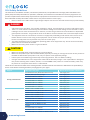
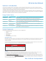
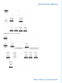
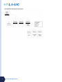
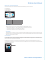
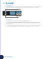
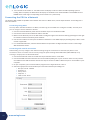
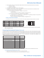
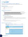
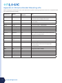
EN Series Power Distribution Unit
& EZ Series Energy Meter
Installation and Operation Manual
For more information, go to www.enlogic.com.
LT-00015-A2 January 2012
2
www.enlogic.com
EN Series User Manual
Table of Contents
PDU Safety Guidelines....................................................................................................... 4
Section 1: Introduction
Enlogic Product Series . ...................................................................................................... 5
Product Components......................................................................................................... 5
Input Power Cord .............................................................................................................. 5
Outlets . ............................................................................................................................ 5
Connection Ports............................................................................................................... 6
OLED Display...................................................................................................................... 6
Menu, Reset, and Unit Status Button................................................................................. 9
Circuit Breakers.................................................................................................................. 9
Section 2: Installation
Before Installation........................................................................................................... 11
Mounting........................................................................................................................ 11
Mounting the PDU in the Server Cabinet.......................................................................... 11
Connecting to a Power Source.......................................................................................... 11
Connecting the PDU to a Network ..................................................................... 12
Connecting Using DHCP.................................................................................................... 12
Connecting with a Serial Connection................................................................................ 12
Connecting Environmental Sensors (Optional). . ................................................................. 13
Connecting an Environmental Sensor Hub........................................................................ 13
Section 3: Enlogic Web User Interface
Supported Browsers ........................................................................................................ 14
Logging In to the Enlogic Web UI...................................................................................... 14
Logging In........................................................................................................................ 14
Changing User Password.................................................................................................. 14
Logging Out..................................................................................................................... 14
Overview of the Enlogic Web UI....................................................................................... 14
Action Menus................................................................................................................... 15
PDU Explorer................................................................................................................... 15
Status Bar........................................................................................................................ 15
Logout button.................................................................................................................. 15
Data Panel....................................................................................................................... 15
Dashboard....................................................................................................................... 15
Renaming the PDU........................................................................................................... 15
Navigating the Action Menus........................................................................................... 15
User Administration......................................................................................................... 15
Device Configuration........................................................................................................ 17
Appendix A: EN Series Bracket Mounting Info................................................................... 20
The Critical Component
3
PDU Safety Guidelines
This document is intended for installers, maintenance professionals, and qualified users of Enlogic power distribution units
(PDUs). Keep this safety information for operation, installation, and maintenance of the PDU and accessory equipment. This
product complies with the latest safety requirements for equipment and accessories for use in a rack mounting environment.
Read and follow all safety information. Failure to do so may result in death or serious injury.
• Electrical Hazard: this PDU contains high voltages. Repairs and service to this PDU should only be performed by
DANGER
•
•
•
•
authorized service providers. This includes installation, testing, and maintenance of internal and external parts.
There is a risk of electrical shock from ground conductor leakage. If the total leakage current exceeds 3.5 mA or
if leakage current of the connected load is unknown, connect the ground terminal of the PDU to a dependable ground/earth connection. The ground terminal on the PDU is an M5 screw hole with a maximum depth of 9mm.
This equipment must be connected to an electrical supply with protected ground outlets and a branch circuit
breaker with the same current rating as the equipment. Test all outlets for proper polarity and grounding.
Failure to comply with this requirement may result in serious injury.
This power distribution unit is intended for providing power to ITE equipment only. Do not connect secondary
power units to the outlets of the PDU.
Make sure the utility power outlet is in good condition.
CAUTION
• Make sure the PDU power cord and plug are in good condition.
• Make sure the power input is disconnected before physically mounting or moving the location of this product. If
the PDU has detachable input power cords, only use power cords supplied by Enlogic.
• Internal parts of the PDU may get extremely hot during operation. Use care before handling.
• Changes and modifications to this equipment could void the warranty. Enlogic is not responsible for damage to this product resulting from accident, disaster, or misuse. Note: If the product is a switched model, power may
be present at a receptacle even when it is switched off.
Follow all local and national codes when installing the PDU. The PDU should be connected to a dedicated circuit protected by a
branch circuit breaker matching the PDU input plug type for your region:
Regions
Europe, International
North America, Japan
4
www.enlogic.com
PDU Input Plug Type
Branch Circuit Breaker Required
IEC60320 C20 Inlet (Removable Power Cord)
CEE 7/4, CEE 7/5, CEE 7/7 Plugs
IEC60309 316P6 or 316P6W
IEC60309 332P6 or 332P6W
IEC60309 363P6 or 363P6W
IEC60309 516P6 or 516P6W
IEC60309 532P6 or 532P6W
IEC60309 563P6 or 563P6W
NEMA 5-15P or NEMA L5-20P
IEC60320 C20 Inlet (Removable Power Cord)
NEMA 5-20P or NEMA L5-20P
NEMA 6-20P or NEMA L6-20P
NEMA 6-30P or NEMA L6-30P
IEC60309 330P9 or 330P9W
NEMA L21-20P or NEMA L15-20P
NEMA L21-30P or NEMA L15-30P
CS8365
IEC60309 460P9 or 460P9W
IEC60309 520P6 or 520P6W
IEC60309 530P6 or 530P6W or NEMA L22-30
16A single-pole
16A single-pole
16A single-pole
32A single-pole
63A single-pole
16A three-pole
32A three-pole
63A single-pole
15A single-pole
20A single-pole
20A single-pole
20A double-pole
30A double-pole
30A double-pole
20A three-pole
30A three-pole
50A three-pole
60A three-pole
20A three-pole
30A three-pole
EN Series User Manual
Section 1: Introduction
This manual is intended to assist in the installation and setup the EN Series PDU. Refer to this manual to properly install and
operate the EN Series PDU. It is recommended that the user follows the procedures as outlined in this manual to assist in proper
installation and prevent damage to the PDU and associated equipment.
The Enlogic family of enterprise-grade rack PDUs includes comprehensive power management, watt-hour energy metering, and
environmental monitoring; all within the industry’s slimmest space-saving design. A large selection of standard and configurable
PDU options is available to meet your specific rack management application.
Enlogic Product Series
Product Series Type
Description
EN1000 Series
Metered
Metered PDUs with real time metering and network monitoring of power loads for
overload avoidance, capacity & load balancing, and energy use optimization.
EN2000 Series
Metered and Outlet
Switched
Remote outlet on/off switching for power-up sequencing, remote power cycling, and
outlet use management combined with all features of the EN1000 Series.
EN5000 Series
Outlet Metered
These outlet metered PDUs combine Individual outlet power and energy metering
with all features of the EN1000 Series.
EN6000 Series
Outlet Metered and
Outlet Switched
Comprehensive management solution includes features of both the EN2000 and
EN5000 Series.
EZ1000 Series
Inline Energy Meters
This energy metering device adds the Enlogic EN1000 series capabilities to any existing basic PDU or stand-alone equipment.
Product Components
Enlogic PDUs include the following components in various configurations:
•
•
•
•
•
•
Input power cord
Outlets
Connection ports
OLED display
Reset button
Circuit Breakers (some models)
Input Power Cord
Most PDUs come with a power cord installed and ready to be plugged into an appropriate receptacle for electricity.
Connect the PDU to an appropriately rated branch circuit. Refer to the label on the PDU for appropriate input
ratings and ranges.
The Input Power Cord is factory set at the top of the PDU. This can be easily rewired to allow for a front-oriented
power cord. (Add instructions here)*** Add images of terminal block (from hanson)
DANGER
When rewiring the Input Power Cord, only use the wires
provided with Enlogic PDUs. Use of other wires is prohibited.
Rewiring must be completed by authorized service providers.
Outlets
The number of outlets on a PDU, and the outlet switching capability varies per model as shown on the _link to
overview tables_. Some PDU models have outlet-switching features to manage individual outlets:
The EN1000, EZ1000, and EN5000 Series do NOT have outlet switching features. Outlets are always On and there
are no outlet LED indicators. EN2000 and EN6000 Series PDUs are equipped with the outlet switching feature and
have a small LED for each outlet. When an outlet LED is lit, that the particular outlet is On. When an outlet LED is
not lit, the particular outlet is Off.
The Critical Component
5
Connection Ports
There are 6 ports on all standard EN Series models, as shown below.
• USB: to connect the EN Series PDU to a USB flash drive to upload
firmware or download log files.
• Ethernet: to connect the EN Series PDU to a computer network
• Serial+Rs485-1: to connect EN and EZ models via RS232 protocol and
reserved for future upgrade
• Rs485-2: reserved for future upgrades
• Sensor-1: to connect to environmental sensors
• Sensor-2: to connect to environmental sensors
OLED Display
The OLED Display is located on the front of the EN Series PDU above the connection ports. When a device powers
up, it takes a few minutes to fully load the software. When the software has completed loading, the OLED display
will show the Startup Menu. The menu buttons just below the OLED Display allow you to scroll through the display
and select the desired information item. The following is an example of the Single Phase OLED Menu:
6
www.enlogic.com
EN Series User Manual
The Critical Component
7
8
www.enlogic.com
EN Series User Manual
Menu, Reset, and Unit Status Button
These are all on the front of the PDU underneath the OLED Display. The are as follows:
1: Reset Button
2: Unit Status LED
3: Menu Buttons
1
2
3
Unit Status LED
LED State
Description
Solid Green
Normal Operation
Solid Red
Alarm State
Blinking Orange
Disconnected from network
Menu Buttons
The Menu Buttons allow a user to navigate through the OLED display. They are:
• Menu–Use this button as a “back” button to go to the previous menu screen.
• Scroll–Use this button to scroll through menu options.
• Select–Use this button to choose an option from a list.
Reset Buttons
The Reset Button is located in the small, recessed hole above the Menu buttons to prevent accidental reset. By
pressing a small pin into the Reset Button hole for 5 seconds, the PDU software with cycle through a soft reboot
without any loss of power to outlets.
Circuit Breakers
EN Series PDUs that are rated over 20A (North American) or 16A (international) have branch circuit breakers. These
circuit breakers trip when the current flowing through the breaker exceeds its rating. When a circuit breaker trips,
power is shut off to any outlets connected to it.
Enlogic PDU circuit breakers sit underneath a protective panel to prevent accidentally tripping the circuits. If a
circuit breaker is tripped, you can easily manually reset to the ON position for normal operation by pressing the ON
button(s), as shown below:
The Critical Component
9
Single-Phase Models
}
For single phase models, each circuit breaker is connected to like-colored outlets. For example, all white outlets
are connected to the white circuit breaker, and all blue outlets are connected to the blue circuit breaker.
}
Three-Phase Models
For 3-phase models, 3 colors are used to identify the 3 different input lines.
•
In standard 400V 3-phase (Wye) configurations, the color of each circuit breaker and outlet correspond
to the appropriate input phase. The PDU is labeled to indicate the input phase associated with each circuit
breaker and outlets.
•
In North America 208V 3-phase (delta) configurations, the color of the circuit breaker corresponds to the
line connections and will include a label of the two connected input phases (i.e., L1-L2, L2-L3, or L3-L1).
10
www.enlogic.com
EN Series User Manual
Section 2: Installation
Before Installation
1. Prepare the installation site: make sure it is not exposed to extreme temperature or humidity. Make sure to allow
space around the Enlogic PDU for cabling and outlet connections.
Note: Enlogic PDUs are designed for maximum operating temperatures of 55–60°C (131–140°F). Refer to
each model’s technical datasheet for specific information.
2. Check the Branch Circuit Rating in the Safety Information section of this manual.
3. Unpack the Enlogic Series PDU. Each model comes with the items below. If something appears to be missing or
damaged, contact your regional Enlogic office.
• Quick Start Guide
• Safety Information Sheet
• Warranty Postcard
4. Use the information provided in the enclosed Warranty Card to register your product online at www.enlogic.com.
Mounting
Select mounting either with or without brackets, depending on the rack style. All Enlogic PDU mounting methods are quick and
convenient.
Mounting the PDU in the Server Cabinet
Enlogic PDUs are built with adjustable mounting pegs for easy, tool-less mounting in most rack enclosure designs.
For these racks, simply adjust the mounting pegs by hand-tightening the pegs into place at the appropriate heights
and secure into the rack.
For a list of racks that require a mounting bracket for proper installation, refer to Appendix A for a list of
compatibility rack manufacturers and installation requirements. (If the standard mounting pegs or mounting brackets
do not comply with your rack configuration contact Enlogic for assistance.) Installation of a bracket, if necessary, may
require a screwdriver.
1. The EN Series PDU comes with tool-less, adjustable mounting pegs for ease and convenience.
2. Determine where the EN Series PDU will be mounted inside the server cabinet.
3. If your rack does not require mounting brackets, skip to step 4. If using mounting brackets, attach the mounting
brackets to the server cabinet. The standard Enlogic mounting brackets are secured to the rack using a screwdriver.
4. Measure the distance between mounting holes in the server cabinet (or the holes in the mounting brackets used)
and adjust the mounting pegs on the back of the PDU accordingly. Note: The mounting pegs on most Enlogic PDUs
can be adjusted between 1472mm and 1584mm in length. Mounting pegs are adjustable from between 554mm
and 676mm on the EN1101, EN2101, and EN5101, and EN6101 series PDUs.
5. With the adjustable pegs set to the correct position, insert the pegs into the server rack mounting holes or into the
mounting brackets.
6. Pull the power cord through the cabinet and tighten the moutning pegs.Proceed with connecting to a power
source.
Note: For specific mounting instructions for various rack manufacturers refer to Appendix A.
Connecting to a Power Source
Check the Branch Circuit Rating in the Safety Information section of this manual before beginning installation. Always follow local
and national codes when installing the PDU. The PDU should be connected to a dedicated circuit protected by a branch circuit
breaker matching the PDU input plug type. Note: When connecting the Enlogic PDU to a Power Source, make sure that you have
enough length in the PDU power cord to reach the PDU power source.
1. Turn the feed circuit breaker off.
2. Make sure that all circuit breakers on the Enlogic PDU are set to ON.
3. Connect each Enlogic PDU to an appropriately rated branch circuit. Note: Refer to the label on the PDU for the
input ratings.
The Critical Component
11
4. Turn the feed circuit breaker on. The OLED screen will display a status bar when the PDU operating system is
loading. When complete, the Main Menu will display on the OLED screen. Switched PDUs in the EN2000 series or
EN6000 series show a light corresponding to each outlet as it is powered up.
Connecting the PDU to a Network
The EN series PDU is DHCP compatible. If the network does not use a DHCP server, see the steps below for “Connecting with a
Serial Connection”.
Connecting Using DHCP
You may obtain the PDU IP address via DHCP, and then log into the Web UI to configure the PDU, at which point
you can assign a static IP address if desired.
1. Connect a standard Ethernet patch cable to the Ethernet port on the EN Series PDU.
2. Connect the other end of the Ethernet cable to the LAN.
3. Make sure the Ethernet port on the PDU shows a solid green light on the left and a flashing yellow light on the right
to indicate successful connectivity to the network.
4. Use the menu buttons to look up the IP address of the device on the OLED display by selecting Setup > Menu > IPv4
or IPv6 as applicable.
5. In a standard web browser, enter the PDU IP address and proceed to configure the PDU as shown in the Enlogic
Web UI Interface section.
Connecting with a Serial Connection
Alternatively, you may configure the network settings using the command line interface (CLI) with a serial
connection. Users can either connect serially using the optional Enlogic RJ45-DB9 Cable (SKU# EA9119) or by
creating a unique pinout as described below.
1. Connect the RJ45 end of the serial cable into the port labeled “Serial” on the PDU.
2. Connect the DB9 end of the cable into the communications (COM) port on your comuter. Note: You may need to
use a DB9 serial to USB connection cable for this step to connect via USB if a DB9 serial port is not available on your
computer.
3. On your computer, open a communications program such as HyperTerminal or PuTTY.
4. Select the appropriate communications port and confirm that the port settings are:
• Bits per second: 115200
• Data bits: 8
• Parity: None
• Stop bits: 1
• Flow control: None
12
www.enlogic.com
EN Series User Manual
5. Use the default initial login indicated below. Note that the username and password are both case sensitive:
• Username: admin
• Password: 12345678
6. The ENLOGIC> prompt appears after you have logged in.
7. To configure network settings, enter the appropriate net commands and press Enter. All commands are case
sensitive. You can type ? to access the commands.
• For the IPv4 DHCP configuration, configure this parameter.
• net tcpip dhcp
• Enter Y to validate and reboot the network management card.
• For the static IPv4 configuration, configure these parameters.
• net tcpip static x.x.x.x (ipaddress) x.x.x.x (netmask) x.x.x.x (gateway) Example: net tcpip static
192.168.1.100 255.255.255.0 192.168.1.1
• Enter Y to validate and reboot the network management card.
Creating a Unique Pinout Connection
To create your own pinout connection for the RJ45 to Serial cable, make the wired connections as shown:
Pin Description
Color
1
Pin
5
2
RS232 RX
White/Green
6
3
RS232 TX
Green
7
4
8
Description Color
Ground
Orange
1
8
Refer to the Web UI section and Using the Command Line Interface section of this manual for more information
about managing the PDU.
Connecting Environmental Sensors (Optional)
To enable the EN Series device to detect Enlogic environmental conditions, connect one or more environmental sensors to the
PDU sensor port 1 or 2. The maximum distance for sensor cabling plugged into the device’s sensor port should not exceed 100
feet (30 m). The maximum number of sensor detection points should not exceed 6. Refer to the table below to determine how
many sensor detection points each sensor takes. For example, if using the 3 Temperature + 1 Humidity sensor (EA9105), only 2
additional sensor points may be connected to the PDU.
Sensor Description
Number of
Sensor Points
ENLOGIC SKU
Alarm Beacon
1
EA9101
Temperature Sensor
1
EA9102
Temperature and Humidity Sensor
2
EA9103
(3) Temperature + (1) Humidity Sensor
4
EA9105
n/a
EA9106
Door switch sensor
1
EA9109
Dry Contact Cable
1
EA9110
Spot Fluid Leak Sensor
1
EA9111
Rope Fluid Leak Sensor
1
EA9112
Smoke Sensor
1
EA9116
Sensor Input Hub (3 sensor inputs)
For more information about Enlogic’s environmental sensors, refer to the Installation sheet, included with each sensor.
Connecting an Environmental Sensor Hub
1. Plug a Sensor Hub into the Sensor 1 or 2 port on the EN Series PDU.
2. Connect up to 3 environmental sensors to any of the OUT ports on the hub.
The Critical Component
13
Section 3: Enlogic Web User Interface (Web UI)
The Enlogic Web UI is used to manage, control, configure, and administer Energy series PDUs and accessories.
Supported Browsers
The Enlogic Web UI is accessible from any of these browsers:
•
•
•
•
Firefox
Internet Explorer® 7 (IE7) or higher version
Safari
Chrome
Logging In to the Enlogic Web UI
Logging In
1. Open a supported web browser and enter the ip address of the EN Series PDU. For example, 10.2.11.24
2. If username and password were configured during the Network Configuration Setup: enter the user name and
password in the appropriate fields. Press Login or Enter.
If username and password were NOT configured during the Network Configuration Setup: use the default
username, admin and password, 12345678. For security purposes, change the password upon login.
Changing User Password
After initial login, change the password:
1. Go to User Administration>Change Password.
2. The Change User Password window opens.
3. Enter the old password and then new password twice to confirm. By default, passwords must be between 8 and
32 characters. To customize password requirements for your organization, refer to the “Security” section of this
manual. Logging Out
Users should logout after each session to prevent unauthorized changes to the system.
1. Select the “logout” button in the top right corner of the screen.
Overview of the Enlogic Web UI
14
www.enlogic.com
EN Series User Manual
Action Menus
The action menus allow an administrator to navigate through the Enlogic Web UI easily and efficiently to manage
various tasks.
• User Administration: allows user to change the account password, add/remove users, and edit user roles
• Device Configuration: allows user to edit/view device, network, and security settings.
• System Administration: allows user to access tools to maintain the device, such as the event and data logs,
device information, and firmware maintenance.
PDU Explorer
The PDU Explorer to the left of the screen displays a menu tree that details the Enlogic device being accessed and
components on or connected to this PDU, such as inlets, outlets, and environmental sensors.
The tree structure comprises three hierarchical levels. Press the “+” (plus) and “-” (minus) buttons to expand/
collapse the menu tree. The PDU name may be customized.
Status Bar
The name of the logged in user can be viewed in the status bar at the bottom of the screen.
Logout button
The Logout button allows users to safely logout of their account for security reasons.
Data Panel
The data panel displays information about the PDU Explorer menu item selected, and provides access to some
features of the Web UI, depending on the menu. Each time a menu item is selected from the PDU Explorer, a new
tab is opened in the data panel. If multiple data tabs are open at once, navigate through them by selecting the
individual tabs. To close tabs, press the “x” button.
Dashboard
When you log in, the Dashboard is displayed by default. The dashboard provides an overview of the status of the
PDU (s) at this IP address.
Renaming the PDU
1. Select the folder of the PDU on the PDU Explorer.
2. Place your cursor in the value field for the PDU Name to edit the name or delete it and replace it with a new name.
Navigating the Action Menus
User Administration
The EN Series PDU comes with a standard Admin profile and a standard User profile. The Admin profile is
typically the system administrator and has the “Admin Role” with full operating permissions. The default User
profile includes the default “User Role” permissions. All other users must be added by the Admin user. Users
are defined by their unique login credentials and by their user role.
Before setting up users, determine the Roles that will be required. Each user must be given a Role. These Roles
define the permissions granted to the user. By default, all new users created by Admin are assigned the default,
standard Role.
Role
Admin
User
Default Permissions
Full permissions that cannot be modified or deleted
Limited permissions that can be modified or deleted. By default, these permissions are:
•
•
•
•
•
•
View Event Settings
View Local Event Log
Change Event Settings
Change PDU, Inlet/Outlet & Overcurrent Protector Configuration
Change Own Password
Switch Outlet (all outlets)
The Critical Component
15
Customized
Permissions for user customized roles can be set as needed.
Change Password
1. Go to User Administration>Change Password.
2. The Change User Password window opens.
3. Enter the old password and then new password twice to confirm. By default, passwords must be between 8 and
32 characters. To configure password requirements to suit your organization, refer to the “Security” section of
this manual. Users
Add: To add a user, go to User Administration>Users,
1. Select New to create a new user profile.
2. Use the Settings tab to enter the following information:
• User Name (required)
• Full Name (required)
• Password(required)
Note: Set password requirements in the Device Configuration menu. By default, passwords must
be 8-32 characters in length, and to have at least one numeric character, and at least one special
character.
• Confirm Password
• Telephone Number (optional)
• Email Address (optional) This will be used to send emails for event actions. If not entered, you will not
receive event emails.
3. Use the SNMPv3 tab to enable and configure SNMPv3 access and enter the desired settings:
• Select “Enable SNMPv3 access.” (Leave this box blank to restrict SNMP access).
• Choose a Security Level:
• NoAuthNoPriv: No authentication and no privacy.
• AuthNoPriv: Authentication and no privacy.
• AuthPriv: Authentication and privacy. This is the default.
• Set the pass phrases to be used for authentication and privacy.
• If you select “Use Password as Authentication Phrase” the authentication pass phrase is
identical to the user’s password.
• (optional) You may choose instead enter a new pass phrase for authentication in the fields
provided: Authentication Pass Phrase:, and Confirm Authentication Pass Phrase
• If you select “Use Authentication Pass Phrase as Privacy Pass Phrase” then the user’s
authentication pass phrase serves as their privacy pass phrase.
• (optional) You may choose instead to enter a new pass phrase for privacy in the fields provided:
Privacy Pass Phrase, and Confirm Privacy Pass Phrase.
4. Use the Roles tab to set admin or user privileges.
5. Use the Preferences tab to set units of measurement.
6. Select OK to save the new user profile.
Modify: To edit a user profile, go to User Administration>Users,
1. Select the user name.
2. Select Edit.
3. Make changes to the user profile. Select OK.
Delete: To delete a user profile, go to User Administration>Users,
1. Select the user name.
Note: To make multiple selections, press Shift+click to highlight multiple profiles.
2. Select Delete.
3. Select Yes to confirm the deletion. Select No to cancel.
16
www.enlogic.com
EN Series User Manual
Roles
To change user roles, privileges, and settings, go to User Administration>Roles. To create a new role,
1.
2.
3.
4.
5.
6.
Select New.
In the Settings tab. enter the Role Name and Description.
In the Privileges tab, select Edit.
Select the privileges to add to that user role. Set parameters if necessary.
Select OK.
Select Save.
To modify a custom user role,
1. Select the role.
2. Select the Edit button.
3. Edit the role name and privileges as needed. Select Save.
To delete a user role,
1. Select the role.
2. Select the Delete button.
3. Select Yes to confirm the change.
Device Configuration
Network Services
SSH or Telnet may be used to access the Command Line Interface. You can configure these various access ports
via the Web UI to enable future management of the Enlogic Series PDU via Command Line Interface.
1. Go to Device Configuration > Network services, and then choose the access method you wish to enable: SSH, or
Telnet, as necessary.
2. When the Settings dialog box pops up for the selected access method, type the port number, check the Enable
box, and then click OK.
Network Service Notes:
• The system does NOT allow users to login in using HTTPS and SSH simultaneously.
• Only one (1) user is granted access to SSH/Telnet/FTP at a time.
• Serial connection takes priority over Telnet and SSH connections. While logged in through the serial
connection, Telnet and SSH access is not permitted.
HTTP
By default, access to EN Series PDU uses HTTP port settings. To change the HTTP port settings:
1. Go to Device Configuration > Network Services > HTTP.
2. In the dialog box, enter a new port number in the corresponding field. Valid range is between 1 and 65535.
3. Select OK to save the changes.
To require users to access the Web UI via HTTPS
1. Go to Device Configuration > Security > Force HTTPS for Web Access.
2. When this option is selected, a confimation dialog box will appear to apply the HTTPS settings.
3. Select Yes to confirm. This will reset the Network Card.
SNMP
Enabling SNMP communication allows the Enlogic Energy Series PDU to send events from an SNMP trap to you
and allows you to view and control the status of outlets. Refer to Section 4: SNMP for instructions on the use of
SNMP with the Enlogic Series PDU.
SSH
Enabling SSH allows for a user to login to the CLI using an SSH client (such as PuTTY) or change the TCP port for
the SSH service.
The Critical Component
17
Telnet
Enabling Telnet allows for a user to login to the CLI using a Telnet client (such as PuTTY) or change the TCP port
for the Telnet service.
FTP
Only Admin users can access FTP settings.
Network Configuration
To modify Internet Protocol (IPv4 or IPv6*) and Settings,
1. Go to Device Configuration > Network Configuration.
2. Select the desired options on the IP Protocol Tab.
3. If using IPv4, open the IPv4 tab and select either Static to manually assign the PDU IP address, or DHCP to set the
PDU Ip address to be auto-configured.
• Select Static to manually assign an IP address. Enter the following information: IP address, Net Mask,
Gateway, Primary DNS server, Secondary DNS server, DNS Suffix (optional)
• Select DHCP if you wish to auto-configure the PDU IP address. Select the “Specify DNS server
manually” checkbox if necessary. Then type the address of the primary DNS server and secondary
DNS server. (I don’t really understand this).
*IPv6 will be available with an upcoming firmware upgrade.
Security
Login Settings
User Blocking will lock you out of the system after a specified number of failed login attempts. To setup User
Blocking:
1.
2.
3.
4.
Go to Device Configurations > Security > Login Settings
Select the Block user on login failure checkbox.
Set the Maximum number of failed logins.
Set the length of time that must pass before the user may attempt login again. Use the Block Timeout dropdown
menu provided.
5. Select OK to save the changes
Login limitations determine how long users are permitted to stay idle before being forced out of the system.
1.
2.
3.
4.
Go to Device Configurations > Security > Login Settings
In the Login Settings dialog box, select the go to the Login Limitations.
Choose the Idle Timeout Period from the dropdown menu.
Select OK to save changes.
Password Policy
You may set a requirement for users to change their password at set intervals using the Password Aging Interval
policy. You may also specify criteria for passwords to ensure that your users enter strong passwords.
1.
2.
3.
4.
Go to Device Configurations > Security > Password Policy
If desired, choose a password aging interval from the Password Interval dropdown menu.
If you wish to specify password criteria, select the Strong Passwords checkbox.
Set the minimum and maximum password length via the dropdown menus provided. Note that the minimum
password length cannot be below 8 characters and the maximum allowed is 32.
5. Select the checkboxes to force users to use specific types of characters within the password.
6. Select OK to save the changes.
18
www.enlogic.com
EN Series User Manual
The Critical Component
19
Appendix A: EN Series Bracket Mounting Info
When mounting your EN Series PDU, refer to the table below for specific mounting requirements and to see if a separate bracket
kit is required for proper mounting.
20
Manufacturer
Models
Separate Bracket Kit
Required?
APC
Netshelter SX
No
Chatsworth
Terraframe
Yes
Chatsworth Power Strip Lashing Bracket, part no. 35086C02 for 42U cabinet, 35086-Cxx for others
Chatsworth
Globalframe
No*
*L-shape PDU Brackets Included with cabinet (mount up
to 2 rack PDUs)
Cisco
R-Series
No
Cooper
Delta3
No
Dell
PowerEdge
No
Eaton
Paramount
Yes
Eaton
Vantage S2
No
Emerson
DCF Rack
No
Emerson
DCM Rack
No*
*More advanced mounting options with Emerson fullheight PDU mounting brackets
HP
G2 Series
Yes
Enlogic part number: EA9120
HP
100 Series
Yes
Enlogic part number: EA9120
HP
Intelligent Series
Rack
Yes
Enlogic part number: EA9120
Knürr
Miracel®
No*
*PDU mounting brackets included with Miracel rack
Knürr
DCM
No*
*Small Bracket Inlcuded with rack; more advanced
mounting options with Emerson full-height PDU
mounting brackets
Panduit
Net-Serv Cabinets
Yes
Panduit part number: SVPDUB
Rittal
TS8
Yes
Enlogic part number: EA9120
Schroff
Varistar
Yes
Contact Schroff
Wrightline
Paramount
Yes
Eaton part number: PDUBRCKT
Wrightline
Vantage S2
No
Wrightline
Vantage
Yes
www.enlogic.com
Note
Cooper part number: PDUMTGBRKT
Eaton part number: PDUBRCKT
Eaton part number: 4PRPWRBRKT
EN Series User Manual
The Critical Component
21
The Critical Component
Enlogic Systems, LLC.
Wildwood
Missouri USA 63040
[email protected]
22
Enlogic Systems
Europe, Ltd.
Worcester
United Kingdom WR1 2PG
[email protected]
www.enlogic.com
www.enlogic.com
Enlogic Systems
Asia Pacific, Ltd.
Tsim Sha Tsui
Kowloon, Hong Kong
[email protected]