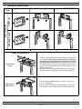
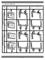
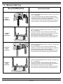
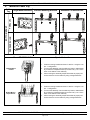
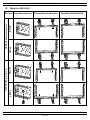
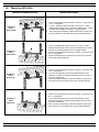
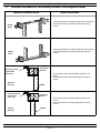
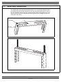
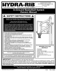
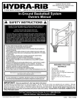
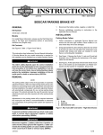
1
PANZONE Overhead Distribution Racks
Part Numbers: PZLRB2U, PZLRB4U, PZLRB6U
INSTALLATION INSTRUCTIONS CM533A
© Panduit Corp. 2011
Included components:
PZLRB2U
PZLRB4U
PZLRB6U
Component
Quantity
Part Number
Packs of #12-24 screws
PZLRB Main Bracket
1
PZLRB2U
2
Rectangular Mounting
Bracket
2
PZLRB4U
4
“L” Shaped Mounting Bracket
2
PZLRB6U
6
3/8-16 Carriage bolt
6
3/8-16 Carriage nut
6
Table of Contents
I. MOUNT ON LADDER RACK..............................................
MOUNT ON SIDE RAIL (bracket down)..........................
BELOW....................................................................
ABOVE....................................................................
MOUNT ON SIDE RAIL (bracket up)..............................
BELOW....................................................................
ABOVE....................................................................
MOUNT BELOW CENTER RUNG..................................
PERPENDICULAR...................................................
PARALLEL...............................................................
2-4
2-3
2-3
2-3
2-3
2-3
2-3
4
4
4
III.
MOUNT ON WYR-GRID.................................................... 8-10
MOUNT ON SIDE WALL (bracket down)........................ 8-9
BELOW..................................................................... 8-9
ABOVE...................................................................... 8-9
MOUNT ON SIDE WALL (bracket up)............................ 8-9
BELOW..................................................................... 8-9
ABOVE...................................................................... 8-9
10
MOUNT BELOW WYR-GRID
10
PERPENDICULAR
10
PARALLEL
II. MOUNT ON CABLE TRAY.................................................
MOUNT ON SIDE WALL (bracket down).........................
BELOW.....................................................................
ABOVE.....................................................................
MOUNT ON SIDE WALL (bracket up).............................
BELOW....................................................................
ABOVE....................................................................
MOUNT BELOW CABLE TRAY......................................
PERPENDICULAR....................................................
PARALLEL................................................................
5-7
5-6
5-6
5-6
5-6
5-6
5-6
7
7
7
IV.
ALTERNATE SIDE MOUNTING OF PZLRB MAIN
BRACKET TO RECTANGULAR BRACKET
V.
POSITIONING OF MOUNTING BRACKETS...................... 12
VI
MOUNT USING THREADED RODS................................... 13
VII.
RECOMMENDED SUPPORT SPACING............................ 14
VIII.
GROUNDING...................................................................... 14
FOR TECHNICAL SUPPORT www.panduit.com/resources/install_maintain.asp
Page 1 of 14
11
INSTALLATION INSTRUCTIONS CM533A
I.
Mount on Ladder Rack
Position Mounting Brackets
Assemble PZLRB2U/4U/6U
BELOW
ABOVE
BELOW
Align Mount Brackets
ABOVE
SIDE MOUNT (bracket up)
SIDE MOUNT (bracket down)
Ladder
Rack
FOR TECHNICAL SUPPORT www.panduit.com/resources/install_maintain.asp
Page 2 of 14
INSTALLATION INSTRUCTIONS CM533A
I.
Mount on Ladder Rack
Mount PZLRB2U/4U/6U
Special Instructions
1.
Side MountBelow
Bracket Down
Side MountAbove
Bracket Down
2.
1.
Position mounting brackets as shown in section V using the
number ‘1’ configuration.
After mounting the assembly, adjust all brackets to proper positions and secure it to the ladder rack using carriage bolts/nuts.
2.
1.
Side MountBelow
Bracket Up
Position mounting brackets as shown in section V using the
number ‘1’ configuration.
After mounting the assembly, adjust all brackets to proper positions and secure it to the ladder rack using carriage bolts/nuts.
2.
1.
Side MountAbove
Bracket Up
Position mounting brackets as shown in section V using the
number ‘1’ configuration.
After mounting the assembly, adjust all brackets to proper positions and secure it to the ladder rack using carriage bolts/nuts.
2.
Position mounting brackets as shown in section V using the
number ‘1’ configuration.
After mounting the assembly, adjust all brackets to proper positions and secure it to the ladder rack using carriage bolts/nuts.
FOR TECHNICAL SUPPORT www.panduit.com/resources/install_maintain.asp
Page 3 of 14
INSTALLATION INSTRUCTIONS CM533A
Mount on Ladder Rack
I.
Position Mounting Brackets
Assemble PZLRB2U/4U/6U
PARALLEL
Align Mount Brackets
PERPENDICULAR
BOTTOM MOUNT
Ladder
Rack
Special Instructions
Mount PZLRB2U/4U/6U
1.
Bottom MountParallel
2.
1.
Bottom MountPerpendicular
2.
Position mounting brackets as shown in section V using the ‘2’ or
‘3’ configuration. While positioning the brackets, only tighten
the brackets on one side of the main bracket and only fingertighten the other set of brackets. Once assembled mount the
fully tightened side to one of the rungs. Slide the other bracket
(which was finger-tightened) such that it locks into position onto an
adjacent center rung.
After mounting the assembly, adjust all brackets to proper positions and secure it to the ladder rack using carriage bolts/nuts.
Position mounting brackets as shown in section V using the ‘2’
or ‘3’ or ‘4’ configuration.
After mounting the assembly, adjust all brackets to proper positions and secure it to the ladder rack using carriage bolts/nuts.
FOR TECHNICAL SUPPORT www.panduit.com/resources/install_maintain.asp
Page 4 of 14
INSTALLATION INSTRUCTIONS CM533A
II.
Mount on Cable Tray
Position Mounting Brackets
Assemble PZLRB2U/4U/6U
BELOW
ABOVE
BELOW
Align Mount Brackets
ABOVE
SIDE MOUNT (bracket up)
SIDE MOUNT (bracket down)
Cable
Tray
FOR TECHNICAL SUPPORT www.panduit.com/resources/install_maintain.asp
Page 5 of 14
INSTALLATION INSTRUCTIONS CM533A
II.
Mount on Cable Tray
Mount PZLRB2U/4U/6U
Special Instructions
1.
2.
Side MountBelow
Bracket Down
3.
1.
2.
Side MountAbove
Bracket Down
3.
1.
Side MountBelow
Bracket Up
2.
3.
1.
Side MountAbove
Bracket Up
2.
3.
Position mounting brackets as shown in section V using the number ‘1’ configuration.
To mount the assembly onto the cable tray sidewall, rotate
assembly so that the L-shaped bracket flanges mount between
the 2nd and 3rd wires from the top of the sidewall.
After mounting the assembly, adjust all brackets to proper positions and secure it to the cable tray using carriage bolts/nuts.
FOR TECHNICAL SUPPORT www.panduit.com/resources/install_maintain.asp
Page 6 of 14
INSTALLATION INSTRUCTIONS CM533A
II.
Mount on Cable Tray
Position Mounting Brackets
Assemble PZLRB2U/4U/6U
PARALLEL
Align Mount Brackets
PERPENDICULAR
BOTTOM MOUNT
Cable
Tray
Mount PZLRB2U/4U/6U
Special Instructions
1.
Bottom MountParallel
2.
3.
1.
2.
Bottom MountPerpendicular
3.
Position mounting brackets as shown in section V using the number ‘1’ configuration.
To mount the assembly onto the cable tray bottom, rotate assembly so that the L-shaped bracket top mounts to any 2 or 3 of the
wires on the bottom of the cable tray.
After mounting the assembly, adjust all brackets to proper positions and secure it to the cable tray using carriage bolts/nuts.
FOR TECHNICAL SUPPORT www.panduit.com/resources/install_maintain.asp
Page 7 of 14
INSTALLATION INSTRUCTIONS CM533A
III.
Mount on WYR-GRID
Assemble PZLRB2U/4U/6U
BELOW
ABOVE
BELOW
Position Mounting Brackets
ABOVE
SIDE MOUNT (bracket up)
SIDE MOUNT (bracket down)
WYR-GRID Align Mount Brackets
FOR TECHNICAL SUPPORT www.panduit.com/resources/install_maintain.asp
Page 8 of 14
INSTALLATION INSTRUCTIONS CM533A
III.
Mount on WYR-GRID
Special Instructions
Mount PZLRB2U/4U/6U
1.
Side MountBelow
Bracket Down
2.
3.
1.
Side MountAbove
Bracket Down
2.
3.
1.
Side MountBelow
Bracket Up
2.
3.
1.
Side MountAbove
Bracket Up
2.
3.
Position mounting brackets as shown in section V using the number ‘1’ configuration.
Locate L-shaped bracket top through corner wires. Locate Lshaped bracket flange notch on the lower sidewall wire. Assemble main and rectangular brackets to L-shaped bracket.
After mounting the assembly, adjust all brackets to proper positions and secure it to the WYR-GRID using carriage bolts/nuts.
Locate L-shaped bracket top through corner wires. Locate Lshaped bracket flange notch on the lower sidewall wire. Assemble main and rectangular brackets to L-shaped bracket.
Position mounting brackets as shown in section V using the number ‘1’ configuration.
Adjust all brackets to proper positions and secure it to the WYRGRID using carriage bolts/nuts.
Position mounting brackets as shown in section V using the number ‘1’ configuration.
To mount the assembly onto the WYR-GRID sidewall, locate
assembly so that the L-shaped bracket flange notch mounts on
the lower sidewall wire.
After mounting the assembly, adjust all brackets to proper positions and secure it to the WYR-GRID using carriage bolts/nuts.
FOR TECHNICAL SUPPORT www.panduit.com/resources/install_maintain.asp
Page 9 of 14
INSTALLATION INSTRUCTIONS CM533A
III.
Mount on WYR-GRID
Assemble PZLRB2U/4U/6U
PARALLEL
Position Mounting Brackets
PERPENDICULAR
BOTTOM MOUNT
WYR-GRID Align Mount Brackets
Special Instructions
Mount PZLRB2U/4U/6U
1.
Bottom MountParallel
2.
3.
1.
2.
Bottom MountPerpendicular
3.
Position mounting brackets as shown in section V using the number ‘1’ configuration.
To mount the assembly onto the WYR-GRID bottom, rotate
assembly so that the L-shaped bracket top mounts to any 2 of
the wires on the bottom of the WYR-GRID.
After mounting the assembly, adjust all brackets to proper positions and secure it to the WYR-GRID using carriage bolts/nuts.
FOR TECHNICAL SUPPORT www.panduit.com/resources/install_maintain.asp
Page 10 of 14
INSTALLATION INSTRUCTIONS CM533A
IV.
Alternate Side Mount of PZLRB Main Bracket to Rectangular Bracket
Mount PZLRB2U/4U/6U
Special Instructions
PZLRB
Below
PZLRB
Above
WYR-GRID (shown)
Ladder Rack
Cable Tray
1.
2.
Position Main Bracket at desired height (select RU spacing).
Mount Main Bracket to Rectangular Brackets using (4)
screws.
1.
2.
Position Main Bracket at desired height (select RU spacing).
Mount Main Bracket to Rectangular Brackets using (4)
screws.
1.
Position Main Bracket at desired depth (inboard or outboard).
Mount Main Bracket to Rectangular Brackets using (4)
screws.
Rectangular
Bracket
2.
Outboard
Mounting
WYR-GRID (shown)
Ladder Rack
Cable Tray
PZLRB
Rectangular
Bracket
1.
2.
Inboard
Mounting
Position Main Bracket at desired depth (inboard or outboard).
Mount Main Bracket to Rectangular Brackets using (4)
screws.
PZLRB
FOR TECHNICAL SUPPORT www.panduit.com/resources/install_maintain.asp
Page 11 of 14
INSTALLATION INSTRUCTIONS CM533A
V.
Positioning of Mounting Brackets
1” Scale Markings
3
2
3
4
2
1
1
4
Recommended Mounting Bracket Positions
To use the markings, place the outsides of both the rectangular brackets on the recommended markings. Fig. 1 shows
how to use marking numbered ‘2’. Fig 2 shows another example in which the smaller brackets are placed using marking numbered ‘3’. Spacing ‘4’ is the minimum recommended spacing for all cases. The one inch scale markings can
also be used if preferred or if using non-standard ladder racks/cable trays. To use scale markings place rectangular
brackets equal distance apart from the center using the scale as a reference.
Fig. 1
1
2
3
4
1
2
3
4
4
3
2
3
2
1
Fig. 2
4
ORIENTATION
1
RECOMMENDED MARKINGS
Below the side rail of Ladder Rack
1
Above the side rail of Ladder Rack
1
Below the Ladder Rack using one rung as support
2- for ladder racks wider than 14”
3- for ladder racks wider than 11”
4- for ladder racks less than 8” wide
Below the Ladder Rack using two rungs as support
2- for center rungs 12” apart
3- for center rungs 9” apart
On the side of Cable Tray oriented downwards
1
On the side of Cable Tray oriented upwards
1
Below Cable Tray
1
On the side of WYR-GRID oriented downwards
1
On the side of WYR-GRID oriented upwards
1
Below WYR-GRID
1
FOR TECHNICAL SUPPORT www.panduit.com/resources/install_maintain.asp
Page 12 of 14
INSTALLATION INSTRUCTIONS CM533A
VI.
Mount Using Threaded Rods
The main bracket can accommodate threaded rods of 1/2”, 3/8” and 5/8” diameters. Place
two threaded rods into the holes provided on top of the main bracket and secure it using 4
nuts (not provided). Note that the 3/8” rod has no specific hole for the threaded rod. It just
slides in the slots and can be adjusted accordingly (Symmetrical installation is highly recommended in this case).
3/8” Groove
1/2” DIA
4
1
2
3
3
2
1
4
5/8” DIA
FOR TECHNICAL SUPPORT www.panduit.com/resources/install_maintain.asp
Page 13 of 14
INSTALLATION INSTRUCTIONS CM533A
VII.
Recommended Support Spacing
The PZLRB is to be mounted centered between supports spaced at 30” apart.
Threaded rod
Threaded rod
30”
WYR-GRID
(shown)
Ladder Rack
Cable Tray
Support
bracket
Support
bracket
PZLRB
VIII.
Grounding
Refer to common bonding network jumper kit. Part Number: RGCBNJ660P22
For instuctions in Local Languages
and Technical Support:
www.panduit.com/resources/install_maintain.asp
www.panduit.com
Page 14 of 14
E-mail:
[email protected]
Fax:
(708)444-6448