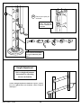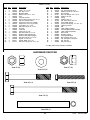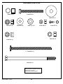
1
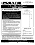
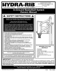
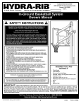
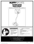
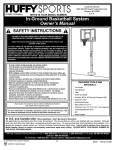
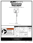
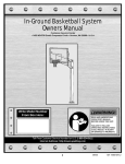
Customer Service Center
N53 W24700 South Corporate Circle
Sussex, WI 53089
U.S.A.
A Huffy Sports Company
WRITE IN YOUR MODEL NUMBER:
In-Ground Basketball System
Owners Manual
SAFETY INSTRUCTIONS
FAILURE TO FOLLOW THESE SAFETY INSTRUCTIONS MAY RESULT IN
SERIOUS INJURY, PROPERTY DAMAGE AND WILL VOID WARRANTY.
Owner must ensure that all players know and
follow these rules for safe operation of the system.
To ensure safety, do not attempt to assemble this system without following the
instructions carefully. Proper and complete assembly, use and supervision is
essential for proper operation and to reduce the risk of accident or injury. A
high probability of serious injury exists if this system is not installed,
maintained, and operated properly. Check entire box and inside all packing
material for parts and/or additional instructional material. Before beginning
assembly, read the instructions and identify parts using the hardware identifier
and parts list in this document.
• If using a ladder during assembly, use extreme caution.
• Two (2) people are recommended for this operation.
• Seat the pole sections properly. Failure to do so could allow the pole sections to
separate during play.
• Before digging, contact utility company to locate underground power cables, gas,
and water lines. Ensure there are no overhead power lines within 20 ft. (7 m) radius
of pole location.
• Climate, corrosion, excessive use, or misuse could result in system failure.
• If technical assistance is required, contact Huffy Sports.
• Minimum operational height is 6' 6" (1.98 m) to the bottom of backboard.
• This equipment is intended for home recreational use only and NOT excessive
competitive play.
• Read and understand the warning label affixed to pole. Label is shown on page 2.
• The life of your basketball pole depends on many conditions. The climate,
placement of the pole, the location of the pole, exposure to corrosives such as
pesticides, herbicides or salts are all important.
• Adult supervision is recommended when adjusting height.
• Serious injury could occur if teeth/face come in contact with backboard, net, or rim.
Most injuries are caused by misuse and/or not following instructions.
Use caution when using this system.
For more information on assembly, placement, proper use and maintenance,
visit The American Basketball Council website at http://www.smarthoops.com.
IMPORTANT!
REQUIRED TOOLS AND
MATERIALS:
•
•
•
•
•
•
•
•
•
Three People
Tape Measure
Shovel and Post Hole Digger
Concrete, 1260 lb. (572 kg) and Container to Mix
Carpenter’s Level
(Two) Step Ladder 8 ft. (2.4 m)
Wrenches: (Two) 1/2, 9/16, 3/4 (One) 3/8
Marker
Vice
Have any questions?...Don’t go back to the store!
We appreciate your purchasing one of our many fine products. We are sure that you will be very satisfied with your selection. Although
great care and effort have been taken, occasionally problems may occur. To ensure prompt and correct handling of any problems, or to
answer any questions, please contact our Toll-Free Customer Service Number listed below. Service will be quicker if you have your
Model Number (found on carton) and assembly instructions ready when calling. PLEASE WRITE YOUR MODEL NUMBER IN THE
SPACE PROVIDED ABOVE.
Toll-Free Customer Service Number for U.S: 1-800-558-5234
Internet Address: http://www.hydra-rib.com
© COPYRIGHT 2002 by HUFFY SPORTS
1
01/03
P/N 211348D
IMPORTANT! WRITE MODEL NUMBER FROM BOX ONTO PAGE 1 OF THIS OWNERS MANUAL
WARNING
FAILURE TO FOLLOW THESE WARNINGS MAY RESULT
IN SERIOUS INJURY AND/OR PROPERTY DAMAGE.
Owner must ensure that all players know and follow
these rules for safe operation of the system.
• See instruction manual for proper installation.
• DO NOT HANG on the rim or any part of the system
including backboard, support braces or net.
• During play, especially when performing dunk type
activities, keep player's face away from the backboard, rim
and net. Serious injury could occur if teeth/face come in
contact with backboard, rim or net.
• Do not slide, climb, shake or play on pole.
• When adjusting height, keep hands and fingers away from
moving parts.
• Do not allow children to move or adjust system.
• During play, do not wear jewelry (rings, watches,
necklaces, etc.); objects may entangle in net.
• Keep organic material away from pole base. Grass, litter,
etc. could cause corrosion and or deterioration.
• Check pole system for signs of corrosion (rust, pitting,
chipping) and repaint with with exterior enamel paint. If
rust has penetrated through the steel anywhere, replace
the pole immediately.
• Check system before each use for proper ballast, loose
hardware, excessive wear and signs corrosion and repair
before using.
• Check system before each use for instability.
• Never play on damaged equipment.
• Keep pole top covered with cap at all times.
1-800-558-5234
201255
P/N 211348D
01/03
2
2/99
1.
Ensure ground is level with playing
surface, then dig pole hole.
PLAYING
SURFACE
WARNING
CONTACT UTILITIES
BEFORE DIGGING.
24" (61 cm)
36" (91.4 cm)
GROUND
SURFACE
2.
Install nut (2) to J-bolt (1)
as shown. Repeat
procedure for other three
J-bolts (1).
2”
(5.08 cm)
2
2
3
IMPORTANT!
Make sure nuts are 2”
(5.08 cm) from top of J-Bolts.
3.
1
2
Install threaded ends of J-bolts (1) through holes in
mounting plate (3) and secure as shown.
1
NOTE: Make sure J-bolts (1) are in the illustrated
position.
NOTE: Nuts on the top of plate are used for leveling
the pole after system is fully assembled.
3
01/03
P/N 211348D
;;
;;
;;
;; ;;
;;
;;;;
;;;;
;;;;
;;;;
;;;;
4.
5.
Fill hole with concrete. Tamp down concrete
to release air pockets and build drainage hill.
Insert J-bolts (1) from mounting plate (3) into
cement as shown. Move assembly around to
release any air pockets in cement, then rest
mounting plate on cement drainage hill. Apply
some pressure to level mounting plate on top of
drainage hill. Level mounting plate and square
with playing surface. Clean off any excess
cement on mounting plate at this time.
PLAYING SURFACE
NOTE: Check leveling of mounting plate (3)
several times while concrete is curing.
3
IMPORTANT!
Front of mounting plate (3)
must be parallel with playing
surface.
WARNING
DO NOT PROCEED TO STEP 6 UNTIL
CONCRETE HAS CURED FOR A
MINIMUM OF 72 HOURS. ALLOW
ADDITIONAL TIME FOR COLD, WET
OR HUMID WEATHER.
P/N 211348D
01/03
4
WARNING
6
TWO PERSON MINIMUM REQUIRED
FOR THIS PROCEDURE.
NOT
FOLLOWING RECOMMENDATION
MAY RESULT IN SERIOUS BODILY
INJURY
AND/OR
PROPERTY
DAMAGE.
5
6.
Upright pole (5). Assemble lower pole flange
onto protruding J-bolts (1) as shown. The
flange will then rest on the nuts (2) from Step 2.
IMPORTANT!
Holes in pole must be parallel
with playing surface.
PLAYING SURFACE
7.
Secure pole (5) flange to mounting plate
(3) as shown. Tighten completely.
Note: Offset holes go
to back of system.
38
4
7
5
4
PLAYING
SURFACE
1
3
5
01/03
P/N 211348D
8.
Insert caps (8) into end of each support arm (9 &
10) as shown. Tap firmly in position.
9.
Apply logo label (11) to lower support arms (10)
as shown. Repeat for opposite side.
10.
Beginning with upper support arms (9) secure
support arms to pole. Continue by securing lower
support arms (10) as shown.
WARNING
TWO PERSON MINIMUM REQUIRED
FOR THIS PROCEDURE. NOT
FOLLOWING RECOMMENDATION
MAY RESULT IN SERIOUS BODILY
INJURY AND/OR PROPERTY
DAMAGE.
12
8
4
4
4
SHORT END
7
IMPORTANT!
4
Do not over tighten.
9
9
8
12
8
4
Note: This bolt
rests outside the
upright pole.
4
8
11
4
7
10
4
8
7
10
8
5
P/N 211348D
01/03
6
11.
Do this strip last.
Cut foam stripping (14) to sizes shown and attach
to flat side of H-frame (13) as shown. Then secure
H-frame to support arms (9 & 10).
14
14
13
NOTE: Install H-Frame (13) with foam striping
toward backboard.
14
WARNING
14
TWO PERSON MINIMUM REQUIRED
FOR THIS PROCEDURE.
NOT
FOLLOWING RECOMMENDATION
MAY RESULT IN SERIOUS BODILY
INJURY
AND/OR
PROPERTY
DAMAGE.
15
14
9
9
13
16
4
4
4
7
4
16
7
IMPORTANT!
Do not over tighten.
10
16
10
4
4
16
4
4
7
7
7
01/03
P/N 211348D
12.
Secure jack brackets (17
& 18) to lower holes in
pole as shown.
19
19
4
18
4
4
4
17
7
7
REAR VIEW
NOTE: REFER TO INSTRUCTION MANUAL ENCLOSED WITH ELEVATOR MECHANISM.
INSTALL BACKBOARD AND GOAL AFTER INSTALLATION OF ELEVATOR
MECHANISM.
P/N 211348D
01/03
8
13.
After Installation of elevator mechanism, position H-frame assembly to lowest point.
Hang backboard onto H-frame (13). NOTE: Backboard frame will rest on top of
H-frame. Secure backboard with hardware as shown-*ONLY Fingertighten bolts (21)
with nuts (22). Repeat procedure for opposite side.
22
23
13
WARNING
TWO PERSON MINIMUM REQUIRED
FOR THIS PROCEDURE.
NOT
FOLLOWING RECOMMENDATION
MAY RESULT IN SERIOUS BODILY
INJURY
AND/OR
PROPERTY
DAMAGE.
9
01/03
P/N 211348D
RIM ASSEMBLY & INSTALLATION
14.
Install carriage bolt (41) through rim (25),
washers (4) and (27) as shown. Tighten
nut (43) completely. Place nut (42) about
half-way up carriage bolt (41) as shown.
41
25
42
WARNING
TWO PERSON MINIMUM REQUIRED FOR THIS
PROCEDURE. NOT FOLLOWING RECOMMENDATION
MAY RESULT IN SERIOUS BODILY INJURY AND/OR
PROPERTY DAMAGE.
27
4
41
43
27
15.
Attach bracket (39) to backboard and support
structure by inserting bolts (26) and washers (24)
through top holes in bracket (39), Tighten nuts (23)
completely.
39
24
26
24
23
39
16.
Insert inner bracket (40) into bracket (39) as shown.
Insert bolts (26) and washers (24) through top holes of
inner bracket (40) as shown, *FROM STEP 13Now tighten backboard/frame nuts (23) completely.
40
24
24
26
23
39
P/N 211348D
01/03
10
40
17.
Insert spacer (20) through rim assembly (25). Place rim assembly on bracket (39) so that carriage bolt (41) is
inserted through hole on top of inner bracket (40). Install hex bolt (44), washers (27) and nut (42) through top
holes on bracket (39) through spacer (20) as shown.Tighten completely.
BOTTOM VIEW
25
27
41
42
27
40
27
44
20
18.
25
39
20
Install rubber grommet (28), concave washer
(29) and center lock nut (30) to carriage bolt (41)
as shown.
41
NOTE
Do not over tighten as rim will not flex
properly. See leveling instructions to
determine how much to tighten nuts
(42) and (30).
28
30
29
11
01/03
P/N 211348D
19. LEVELING INSTRUCTIONS:
Place level on rim (25) and adjust nut (42) until
level. Tighten nut (30) to set rim tension for
playing.
25
42
30
20.
Apply logo label (33) to cover plate (31). Install
cover plate (18) on rim (25) using self tapping
screws (32) as shown.
31
33
NOTE ORIENTATION OF COVER PLATE
32
21.
Secure net (34) to
rim (25).
34
1
NOTE: Official rim height is
10 ft. (3.05 m) from top of rim
to playing surface.
25
2
10 feet
(3.05 m)
OUTSIDE VIEW
4
3
P/N 211348D
01/03
12
22.
Check leveling at this time. Pole should
be level in all directions. NOTE: If
adjustment is necessary, adjust system by
rotating the nuts (2) between mounting
plate (3) and pole flange. (Referred to in
Step 6.) After system is leveled,
completely tighten nuts (7) above pole
flange.
23.
Apply height adjustment label (37) to
front of pole as shown.
37
REGULATION
RIM HEIGHT IS
10 FEET (3.05 m).
IMPORTANT!
If pole pad is used, position label (37)
above the pole pad.
10 feet
(3.05 m)
13
01/03
P/N 211348D
36
24.
Secure pole pad (36)
as shown.
NOTE: Pole pad may
NOT be included in
this model.
NOTE: Elevator mechanism
may appear differently than
shown.
Height Adjustment
Refer to height adjustment
instructions for operating
elevator mechanism.
NOTE: If height adjustment is difficult to operate, you may
have over tightened the areas indicated. Refer to Step 10
and Step 11.
P/N 211348D
01/03
14
PARTS LIST
Item Qty.
1
2
3
4
5
6
7
8
9
10
11
12
13
14
15
16
17
18
19
20
21
22
4
8
1
34*
1
1
11
8
2
2
2
4
1
1
1
4
1
1
3
1
2
4
Item Qty.
Part No.
Description
206677
202459
920578
203474
980830
220590
206340
220589
906658
906678
220586
220588
908058
206685
206681
202856
906277
906276
220048
220064
206311
203113
J-Bolt, 1/2”-13 x 24”
Nut, Hex 1/2”-13
Mounting Plate
Washer, Flat 1/2” x 1” O.D.
Pole
Pole Cap, Square
Nylon Insert Lock Nut, Hex 1/2”-13
Cap, Arm Support Insert
Support Arm, 42” Long, (Upper)
Support Arm, 52” Long, (Lower)
Logo Label, 15” x 1 3/4”
Bolt, Hex Flange 1/2”-13 x 9”
H-Frame
Foam Roll
Foam Pad, 4” x 28”
Bolt, Hex Head,1/2”-13 x 4”
Bracket, Jack Support (Left)
Bracket, Jack Support (Right)
Bolt, Hex Flange, 1/2”-13 x 6”
Spacer, 5 x 1/2” O.D.
Spacer, Black .53” x 1/2”
Bolt, Hex Flange 5/16”-18 x 2 1/2”
23
24
25
26
27
28
29
30
31
32
33
34
35
36
37
38
39
40
41
42
43
44
8
8
1
4
5*
1
1
1
1
2
1
1
1
1
1
4
1
1
1
2
1
1
Part No.
Description
203100
203218
920263
201611
203232
200484
200323
201124
960043
220140
220569
204282
220565
206555
201262
200517
920262
920038
220065
203063
203017
203439
Nut, Hex Flange 5/16”-18
Washer, Flat 5/16” x 7/8” O.D.
Rim, Orange
Bolt, Hex Flange, 5/16”-18 x 3”
Washer, 3/4 O.D.
Spring
Washer, Flat, 1.5"
Nut, Hex Locking, 5/16-18
Cover Plate, Orange
Screw, Self Tapping, 1/4 - 20 x 1/2
Label Logo Circle
Net
Label, Height Indicator
Pole Pad (May Not Be Included)
Label, Height Adjustment
Bolt Covers
Bracket, Orange
Inner Bracket, Black
Bolt, Carriage 3/8 x 5 1/2
Nut, Hex Nylon Locking 3/8
Nut, Hex 3/8
Bolt, Hex 3/8 x 6
* You May Have Extra Parts With This Model.
HARDWARE IDENTIFIER
Item #2 (8)
Item #4 (34)*
Item #7 (11)
Item #22 (4)
Item #16 (4)
Item #19 (3)
Item #20 (1)
15
01/03
P/N 211348D
HARDWARE IDENTIFIER
Item #26 (4)
Item #21 (2)
Item #29 (1)
Item #23 (8)
Item #24 (8)
Item #27 (5)*
Item #30 (1)
Item #43 (1)
Item #42 (2)
220065
Item
#41 (1)
Item #44 (1)
WARRANTY CARD:
Please remember to complete your product
registration form on-line at:
www.hydrarib.com/warrantycard
P/N 211348D
01/03
Item #32 (2)
16